EP0264474A1 - Procédé de, et machine pour le brochage par rotation de pièces à symétrie de révolution - Google Patents
Procédé de, et machine pour le brochage par rotation de pièces à symétrie de révolution Download PDFInfo
- Publication number
- EP0264474A1 EP0264474A1 EP86114599A EP86114599A EP0264474A1 EP 0264474 A1 EP0264474 A1 EP 0264474A1 EP 86114599 A EP86114599 A EP 86114599A EP 86114599 A EP86114599 A EP 86114599A EP 0264474 A1 EP0264474 A1 EP 0264474A1
- Authority
- EP
- European Patent Office
- Prior art keywords
- workpiece
- tool
- machine
- carrier
- tool carrier
- Prior art date
- Legal status (The legal status is an assumption and is not a legal conclusion. Google has not performed a legal analysis and makes no representation as to the accuracy of the status listed.)
- Granted
Links
- 238000000034 method Methods 0.000 title claims description 21
- 238000005520 cutting process Methods 0.000 claims abstract description 71
- 230000033001 locomotion Effects 0.000 claims abstract description 25
- 239000000969 carrier Substances 0.000 claims description 30
- 238000003754 machining Methods 0.000 claims description 18
- 230000002093 peripheral effect Effects 0.000 claims description 4
- 238000010276 construction Methods 0.000 abstract description 6
- 230000037431 insertion Effects 0.000 abstract 2
- 238000003780 insertion Methods 0.000 abstract 2
- 238000013461 design Methods 0.000 description 9
- 239000012530 fluid Substances 0.000 description 8
- 230000002349 favourable effect Effects 0.000 description 4
- 238000004519 manufacturing process Methods 0.000 description 4
- 230000008878 coupling Effects 0.000 description 3
- 238000010168 coupling process Methods 0.000 description 3
- 238000005859 coupling reaction Methods 0.000 description 3
- 230000000694 effects Effects 0.000 description 3
- 238000006073 displacement reaction Methods 0.000 description 2
- 235000005505 Ziziphus oenoplia Nutrition 0.000 description 1
- 244000104547 Ziziphus oenoplia Species 0.000 description 1
- 230000006978 adaptation Effects 0.000 description 1
- 238000011156 evaluation Methods 0.000 description 1
- 230000000977 initiatory effect Effects 0.000 description 1
- 239000000463 material Substances 0.000 description 1
- 238000012545 processing Methods 0.000 description 1
- 238000003860 storage Methods 0.000 description 1
- 238000012546 transfer Methods 0.000 description 1
Images


Classifications
-
- B—PERFORMING OPERATIONS; TRANSPORTING
- B23—MACHINE TOOLS; METAL-WORKING NOT OTHERWISE PROVIDED FOR
- B23D—PLANING; SLOTTING; SHEARING; BROACHING; SAWING; FILING; SCRAPING; LIKE OPERATIONS FOR WORKING METAL BY REMOVING MATERIAL, NOT OTHERWISE PROVIDED FOR
- B23D37/00—Broaching machines or broaching devices
- B23D37/005—Broaching machines or broaching devices for cylindrical workpieces, e.g. crankshafts
-
- B—PERFORMING OPERATIONS; TRANSPORTING
- B23—MACHINE TOOLS; METAL-WORKING NOT OTHERWISE PROVIDED FOR
- B23D—PLANING; SLOTTING; SHEARING; BROACHING; SAWING; FILING; SCRAPING; LIKE OPERATIONS FOR WORKING METAL BY REMOVING MATERIAL, NOT OTHERWISE PROVIDED FOR
- B23D43/00—Broaching tools
- B23D43/06—Broaching tools for cutting by rotational movement
- B23D2043/063—Broaching tools for cutting by rotational movement with cutters mounted externally
-
- Y—GENERAL TAGGING OF NEW TECHNOLOGICAL DEVELOPMENTS; GENERAL TAGGING OF CROSS-SECTIONAL TECHNOLOGIES SPANNING OVER SEVERAL SECTIONS OF THE IPC; TECHNICAL SUBJECTS COVERED BY FORMER USPC CROSS-REFERENCE ART COLLECTIONS [XRACs] AND DIGESTS
- Y10—TECHNICAL SUBJECTS COVERED BY FORMER USPC
- Y10T—TECHNICAL SUBJECTS COVERED BY FORMER US CLASSIFICATION
- Y10T409/00—Gear cutting, milling, or planing
- Y10T409/10—Gear cutting
- Y10T409/109063—Using reciprocating or oscillating cutter
- Y10T409/109222—Broach
-
- Y—GENERAL TAGGING OF NEW TECHNOLOGICAL DEVELOPMENTS; GENERAL TAGGING OF CROSS-SECTIONAL TECHNOLOGIES SPANNING OVER SEVERAL SECTIONS OF THE IPC; TECHNICAL SUBJECTS COVERED BY FORMER USPC CROSS-REFERENCE ART COLLECTIONS [XRACs] AND DIGESTS
- Y10—TECHNICAL SUBJECTS COVERED BY FORMER USPC
- Y10T—TECHNICAL SUBJECTS COVERED BY FORMER US CLASSIFICATION
- Y10T409/00—Gear cutting, milling, or planing
- Y10T409/40—Broaching
- Y10T409/400175—Process
-
- Y—GENERAL TAGGING OF NEW TECHNOLOGICAL DEVELOPMENTS; GENERAL TAGGING OF CROSS-SECTIONAL TECHNOLOGIES SPANNING OVER SEVERAL SECTIONS OF THE IPC; TECHNICAL SUBJECTS COVERED BY FORMER USPC CROSS-REFERENCE ART COLLECTIONS [XRACs] AND DIGESTS
- Y10—TECHNICAL SUBJECTS COVERED BY FORMER USPC
- Y10T—TECHNICAL SUBJECTS COVERED BY FORMER US CLASSIFICATION
- Y10T409/00—Gear cutting, milling, or planing
- Y10T409/40—Broaching
- Y10T409/404375—Broaching with plural cutters
-
- Y—GENERAL TAGGING OF NEW TECHNOLOGICAL DEVELOPMENTS; GENERAL TAGGING OF CROSS-SECTIONAL TECHNOLOGIES SPANNING OVER SEVERAL SECTIONS OF THE IPC; TECHNICAL SUBJECTS COVERED BY FORMER USPC CROSS-REFERENCE ART COLLECTIONS [XRACs] AND DIGESTS
- Y10—TECHNICAL SUBJECTS COVERED BY FORMER USPC
- Y10T—TECHNICAL SUBJECTS COVERED BY FORMER US CLASSIFICATION
- Y10T409/00—Gear cutting, milling, or planing
- Y10T409/40—Broaching
- Y10T409/4077—Cutter support or guide
Definitions
- the invention relates to a method for the rotary broaching of rotationally symmetrical workpieces with a tool with blades arranged and moved in a radial plane to the workpiece and on a curved path, which can be brought into engagement with the workpiece, and a device for carrying out the method.
- the broaching tools should no longer be designed as straight broaching tools that have to be displaced during machining, but rather that the cutting elements of the broaching tools should be distributed uniformly over a circumferential area of 360 ° over a spiral contour.
- a corresponding sketch is shown in the prospect of the Heinlein company "New manufacturing process for mass production”. The sketch is titled “Rotation-Turning Rooms”. The broaching tool is no longer moved on a slide to generate the feed movement, but rotated around an axis. The spiraling contour of the line on which the cutting elements are arranged ensures the infeed. The way in which the tool is received and is movable in addition to the mentioned rotary movement, cannot be found in these documents.
- the object of the invention is to propose a method of the type described in the introduction, in the use of which the idle times can be reduced. Furthermore, a simpler machine structure should be possible. A machine for implementing the method according to the invention is also to be proposed.
- the object with regard to the method is achieved according to the invention in that the loading and unloading takes place with workpieces, without interrupting the movement of the tool, but after machining by the last cutting edge in the area of a subsequent one, from Cutting edge free zone of the tool.
- modern feeding devices such a workpiece change from smaller shafts or, for example, crankshafts from motor vehicle engines can be carried out in a few seconds.
- the gap in the tool can be dimensioned such that the first cutting edge is again at the beginning of the work process immediately after the workpiece change process has ended and machining therefore begins on the workpiece. In this way, return stroke times or idle times to bring the tool into the working position can be minimized or completely avoided. At the same time, a separate slide with drive and control for a radial movement of the tool can be omitted in the machine design.
- An alternative of the method according to the invention provides that after the processing of the workpiece by the last cutting edge, the tool is moved in the same direction of movement into a workpiece change position and is stopped for the period of the workpiece change.
- This also achieves the advantages already described, although control means for stopping the tool in the tool changing position must be provided on the necessary machine. It should be emphasized in this connection that the movement of the tool does not necessarily have to be exclusively a rotary movement around a fixed center point. This is only one way to move cutting on a curved path. It should also be pointed out that the term loading and unloading generally refers to the introduction of a workpiece into the work area of a assigned tool or removing from this work area.
- At least one zone following a last cutting edge and free of cutting edges is provided as the workpiece change position on the tool and is moved and stopped in the position opposite the workpiece. This is the easiest way to create and retract a workpiece change position.
- a machine is proposed with a workpiece spindle which can be driven in rotation about the machine axis and a movable tool carrier with cutting edges arranged thereon, the tool carrier allowing movement of the cutting edges on a curved path, in which means are provided which provide an angular position of the tool carrier for the Detect the start of work and an angular position of the tool holder for removal, in the angular position for removal a zone free of cutting edges facing the workpiece, and forward control signals for loading and unloading and at least the start of work to the machine control.
- This enables the correct position of the tools for initiating and carrying out the workpiece change to be detected with simple means and the machine to be controlled accordingly.
- the workpiece spindle can be moved into a predetermined, fixed angular position. This is particularly advantageous when the workpiece has asymmetrical shapes, such as. B. in a crankshaft. There is then a preferred workpiece position for the workpiece change, which can be carried out when the workpiece spindle can be retracted and retracted into a predetermined fixed angular position.
- An embodiment of the invention provides that at least one further tool carrier is provided. This makes it possible to use at least two tools, either alternately or simultaneously, depending on the machine design, the tools used also being able to be the same or different and being able to be arranged on the tool carrier in different positions.
- the tool carriers are arranged in at least one rotatable carrier drum.
- the tools can be brought into the working position or removed from the working position in a simple manner.
- the axis of rotation of the carrier drum is arranged outside the machine axis. This creates space for an unproblematic workpiece change that does not force unnecessary idle times.
- the axis of rotation of the carrier drum is arranged parallel to the machine axis. This is an advantageous and unproblematic arrangement.
- the tool carriers are designed as spindles, in parallel Anor extension.
- Spindles are easy to store and the rotary drive is easy to store.
- the transfer of the rotary movement to associated tools is also simple, so that the necessary tool movement can be generated in the simplest way by this construction.
- the spindles are carried by at least one rotatable carrier drum.
- the advantageous construction of the carrier drum has already been mentioned.
- spindles as tool carriers are also particularly easy to store in carrier drums.
- the overall structure is simplified.
- each carrier drum can be retracted into at least two predetermined angular positions.
- the tools can be moved easily and automatically and brought into a desired position.
- cutting edge carriers with cutting edges are arranged in the circumferential direction on the tool carrier, at least one peripheral region being free of cutting edge carriers to form a removal gap.
- a tool is built up from individual sections, it being possible to simply omit such sections on the circumference in order to form a removal gap.
- a special shape of the tool to form such a removal gap is then no longer necessary.
- the use of a tool holder on the cutting edges Can be arranged carrier therefore achieves the intended purpose of enabling the method according to the invention and at the same time represents a simplifying feature of the machine according to the invention.
- At least two headstocks in an opposing arrangement and with a common center line of the workpiece spindle are provided, and at least one further headstock for the rotationally drivable tool carrier, the center line of each tool carrier running parallel to the center line of the workpiece spindles .
- each headstock for a tool carrier is arranged to be displaceable and positionable parallel to the center line of the workpiece spindles.
- the assigned tools can be set to axially different positions of the workpiece and to axially differently located work stations on the workpiece.
- each headstock for a tool carrier is arranged to be displaceable and positionable vertically to the center line of a tool carrier. In this way it is possible on the one hand to set the entire device to different diameter positions of the tools and on the other hand to different finished diameters on the workpiece with the same tool dimensions.
- each headstock for a workpiece spindle is displaceable and is positioned positionable. This also enables additional adjustment to different workpiece lengths.
- the machine bed is arranged vertically, with the center lines of the spindles running horizontally. In this way, on the one hand, favorable access to the workpiece and, on the other hand, more favorable chip removal is achieved.
- a further embodiment is to be seen in the fact that the machine bed is designed as a portal.
- the free space of the portal allows easy access to a chip pit.
- a vertical arrangement of the machine bed in the manner proposed according to the invention favorable access to a chip pit is possible anyway, and at the same time the workpiece can be clocked through the machine, that is to say without problems, through the portal of the machine bed.
- each tool headstock is arranged above the associated workpiece headstocks. This in turn provides favorable access to the workpiece and at the same time prevents tools and tool carriers from being burdened by dirt and chips.
- the rotational speed of the workpiece spindle and / or tool carrier can be changed.
- the machining volume generated per unit of time can be kept constant or also changed.
- an adaptation to the vibration behavior of the workpiece and / or to the cutting performance of the cutting inserts in engagement in each case can take place. The performance of the machine and the quality of the work result can thus be optimized.
- FIG. 1 The basic concept of the construction of a machine according to FIG. 1 is similar to the construction of a known lathe.
- a machine bed 27 is attached to a foundation 28.
- Two headstocks 29 and 30 are slidably arranged on the machine bed.
- Both headstocks 29 and 30 carry workpiece spindles 16 which are rotatably mounted in the headstocks and can be driven via the motors 31 and 32.
- the workpiece spindles 16 have conventional devices for receiving a workpiece 1 on the heads, which are not described in more detail.
- the motors 31 and 32 which are controlled synchronously via a machine control 33, serve this purpose.
- the headstocks 29 and 30 have on their underside in the machine bed 27 projecting driver pieces 35 and 36, each with a continuous threaded bore, the thread pitch of the one driver piece being opposite to the thread pitch of the other driver piece.
- a corresponding threaded spindle 37 with the thread belonging to the respective driving piece 35 and 36 passes through both driving pieces 36 and 35, the threaded spindle 37 being rotatably and axially immovably mounted in the bearing block 38 which is fastened to the foundation 28.
- the threaded spindle 37 can be connected via a coupling 39 to an electric motor 40, which in turn is connected to the machine control 33 and controlled from there. By actuating the motor 40, the headstocks 29 and 30 can be moved in the direction of arrow 41 and in the opposite direction.
- a workpiece 1 can be removed or also used and clamped by this displacement.
- Such constructions are known and therefore do not have to be described separately here. So that this can all be done in a desired rotational position if necessary, z. B.
- the motor 31 has a rotary encoder 42 arranged on its axis, which gives its information to the machine control 33. This is particularly the case when the workpiece 1 z. B. is a crankshaft.
- a tool carrier 14 designed as a spindle is rotatable in the headstock 30 below the workpiece spindle 16 and is mounted with its axis parallel to the axis of the workpiece spindle 16.
- This tool carrier 14 can be driven in rotation by means of a worm gear and a motor 43 (not specified).
- the motor 43 is again connected to the machine control 33.
- the tool holder 14 is connected to a rotation angle transmitter 12, which in turn transmits its impulses to the machine control 33, so that this rotation angle position of the tool holder 14 is always known.
- the rotational speed of the tool carrier 14 is thereby also known.
- the tool carrier 14 has, between the headstocks 29 and 30, a tool 4 with cutting edges for broaching the workpiece 1.
- the workpiece and the tool are in a relative position to one another, as shown in FIG. 2.
- the tool carrier 14 is rotatably but axially immovably mounted in the headstock 30, the tool 4 always maintains its relative position to the headstock 30. This can be advantageous in mass production if the workpieces 1 can always be clamped in exactly the same positions.
- the tool carrier 4 for example in the interior of the headstock 30, as a splined shaft on which the worm wheel for the connection to the motor 43 is slid axially. The tool carrier 14 can then be displaced axially as desired via a screw drive or a hydraulic drive.
- the tool carrier 14 does not necessarily have to lie in a vertical plane through the axis of the workpiece spindle 16, but may have an arrangement to the side thereof. If one considers the plane 44 according to FIG. 2 as such a vertical plane, then an arrangement as shown in FIG. 4 would be possible with the same relation.
- the motor 31 and possibly the motor 32 are put into operation via the machine control 33 at the necessary speed for a sufficient cutting speed of the workpiece 1, so that the workpiece 1 rotates correspondingly quickly.
- the tool 4 is positioned so that the zone 9 of the workpiece 4 free of cutting edges faces the workpiece 1.
- the tool 4 has individual suitable cutting edges, of which the cutting edge with reference number 7 is the last one.
- the tool 4 penetrates with its cutting edges radially ever deeper into the region of the workpiece 1 to be machined during the rotational movement.
- the last cutting edge 7 is used on the workpiece and completes the intended activity there.
- the zone 9 free of cutting edges turns towards the workpiece 1 and the workpiece 1 can now be changed during the continuous further rotation of the tool 4 in the direction of the arrow 46, which is indeed slow. Such a change occurs with modern feeders within a few seconds.
- the threaded spindle 37 is moved via the motor 40, which has received a corresponding control pulse from the machine control 33, such that the headstocks 29 and 30 move apart in the direction of the arrow 31.
- the machine control 33 receives the information when, ie in which angular position of the tool 4 this can take place, from the rotary angle transmitter 12.
- the motors 31 and 32 are first stopped and the feed device is informed via the machine control 33.
- the feed device not shown, now grips the workpiece 1 and at the same time holds another workpiece 1 ready for the change. Now the headstocks 29 and 30 move apart and the finished workpiece 1 is removed and a workpiece 1 that has not yet been machined is inserted at the same time.
- the feed device informs the machine control 33 of the process that has taken place, which then emits a pulse to the motor 40, so that the headstocks 29 and 30 move together again in the opposite direction to the direction of the arrow 41 and thereby clamp the newly inserted workpiece 1.
- the tool carrier 14 can continue to run continuously with the tool 4.
- the clamping of the workpiece that has taken place can be determined, for example, by the machine controller 33 via the current consumption of the motor 14, which then puts motors 31 and 32 into operation again and possibly also drives the motor 43 again.
- the machine control 33 receives corresponding information about the rotary angle encoder 42.
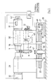
- Figure 3 shows a device in principle as Figure 1, but with two workpiece spindles and two tool carriers. For the sake of clarity, only the right half of the machine is shown. This right side is repeated in mirror image on the other side of the plane marked with arrow A.
- a machine according to FIG. 3 essentially consists of a headstock 47 to which an opposite headstock, not shown, corresponds.
- a shaft 48 is rotatably mounted in the headstock 47.
- the rotational speed and rotational position of the shaft 48 are reported to the machine control 34 via a resolver 49.
- the shaft 48 protrudes with a flying end into the working area between the opposing headstocks 47 of the machine.
- a spindle drum 43 rotatable with the shaft 48 or on the other side 43 ⁇ is provided in a rotationally fixed and axially non-displaceable manner.
- This spindle drum 43 consists essentially of two disks arranged parallel to one another at a distance on the shaft 48, of which the disk closest to the end of the shaft 48 has a toothing for a worm wheel on the outside, into which one of a motor 50 driven worm gear, not specified engages.
- the spindle drum 23 each has a bearing point for the storage of a workpiece spindle 17 or 18.
- the workpiece spindles 17 and 18 have usual clamping means for receiving a workpiece 2 or 3 at the front end, but are axially displaceably mounted in the spindle drum 23.
- An axial displacement of the workpiece spindles 17 and 18 can be effected via fluid cylinders 51, which are provided at the rear end of the workpiece spindles 17 and 18 and are supported on the spindle drum 23 with their cylinder housing.
- An axially acting and unspecified spring arranged in the cylinder housing of the fluid cylinders 51 ensures the clamping movement and the clamping force of the workpiece spindles 17 and 18, respectively.
- To release the fluid cylinders 51 on the piston side facing away from the spring side the pistons in the cylinders are still closed descriptively acted upon by a fluid.
- each workpiece spindle 17 and 18 has a tooth 52 and 53 connected to it in a rotationally fixed and axially immovable manner.
- each gear 52 or 53 can mesh with a gear 54 which is driven by a motor 55.
- Motor 55 is connected to machine control 34 and is controlled from there.
- a carrier drum 20 consisting of two disks arranged at a distance and parallel to one another, in which broaching tools 5 and 6 are arranged on tool carriers 15 and 19.
- the tool carriers 15 and 19 are designed as shafts which are rotatably mounted in the said disks of the carrier drum 20.
- the carrier drum 20 itself is rotatably supported about the axis of rotation 21 in corresponding stands 56 and 56 ⁇ .
- the axis of rotation 21 is connected in a rotationally fixed manner to a worm wheel 57 which can be driven by a motor 58 which in turn is connected to the machine control 34.
- a worm wheel 57 opposite the worm wheel 57, is introduced coaxially to the axis of rotation 21, a drive shaft (not specified in any more detail) which is rotatably connected to a worm wheel 59.
- this drive shaft is rotatably connected to a gear 60 that meshes with pinions 61.
- the cracks 61 are arranged coaxially to the shaft-shaped tool carriers 15 and 19 and can be connected to these shafts in a rotationally fixed manner by means of a coupling (not specified in more detail).
- resolvers which are connected to a device 13 via a control line 62 or 63.
- the worm wheel 57 also has a resolver (not specified in any more detail) which is connected to the device 13 via the control line 64.
- the device 13 itself is connected to the machine control 34 via the control line 65.
- a motor 66 is also connected on the one hand to the machine control 34 and on the other hand mechanically to the worm wheel 59, so that the tools 5 and 6 can also be set in rotation by actuating the motor 66.
- These tools 5 and 6 have zones 10 and 11 free of cutting edges, as shown in FIG.
- the shaft 48 has a distributor ring 67 surrounding it, which is surrounded by a fixed distributor connection.
- Hydraulic lines 69 and 70 are guided in the shaft 48 and are guided via the spindle drum 23 and through the workpiece spindles 17 and 18, respectively, to the front of the piston in the fluid cylinders 51.
- the hydraulic lines 69 and 70 are passed on to the valve 71 via circumferential connection channels in the distributor connection 68.
- This valve has three switching positions and four connections. In the middle position shown, both hydraulic lines 69 and 70 are placed on the tank 72. The two other switching positions enable one or the other fluid cylinder 51 to be acted upon selectively.
- the valve 71 itself is connected to the machine control 34 by its actuating magnets.
- a hydraulic pump 73 which is driven by a motor 74, which in turn is connected to the machine control 34, provides the necessary pressure medium.
- the machine controller 34 is also connected in a suitable manner to a feed device, not shown, so that the activity of the feed device can be coordinated with the machine cycle.
- Figure 3 shows a machine according to the invention in side view with two clamped workpieces, of which the workpiece 2 is just finished, while the workpiece 3 is still completely unworked.
- the workpiece 2 must now be removed from the working area of the tool 5 and the workpiece 3 must be transported there.
- the device 13 receives information via the control line 64 that the tool 5 has been working on the workpiece 2. If the rotary encoder assigned to the tool 5 with the control line 62 is connected to the device 13, the device 13 also receives the information via the control line 62 that the tool 5 has assumed a workpiece change position, as shown in FIG.
- the information supplied to the device 13 via the control line 62 and 64 is supplied to the machine control 34 via the line 65.
- the machine control 34 causes the motor 55 to be put out of operation and causes the feed device with an empty gripper and a gripper filled with a new workpiece to be ready in the change position.
- the motor 66 can be stopped via the machine control 34, but can also run through. It is also possible to simply release the clutch assigned to the score 61.
- the machine control unit 34 starts the motor 50 and thus rotates the spindle drum 23 by 180 °.
- the machine control receives the corresponding angle information from the resolver 49.
- the workpiece 3 is now in the position of the workpiece 2 shown in the drawing, so that the gear 53 meshes with the gear 54 of the motor 55.
- the motor 50 is stopped by the machine control 34 so that the workpiece 3 remains in the working position and the motor 55 rotates the workpiece 3.
- the tool 5 can start machining the workpiece.
- a gripper of the feed device, not shown, is placed on the workpiece 2, which is now in the upper position, and the valve control 71 then switches the valve 71 into the switch position with the crossed arrows.
- the workpiece spindle 17 is moved backwards along the machine axis 22 and the workpiece 2 can now be removed from the feed device.
- the feed device brings a new workpiece into the clamping position and reports this to the machine control 34, which then the valve 71 moves back into the middle position, whereby the line 69 is placed on the tank and the workpiece spindle 17 is pushed forward again by the axially acting spring in the fluid cylinder 51 and the newly inserted workpiece is thus clamped.
- the spindle drum 23 By rotating the spindle drum 23 again by 180 °, this newly inserted workpiece can now be brought back into the working position in order to be processed by the tool 5.
- the machine according to FIG. 3 can be equipped with fixed tools 5, as described for FIG. 1.
- a tool changing device as shown in FIG. 3.
- two stands 56 and 56 ⁇ attached to the foundation, which serve as a bearing stand for an axis of rotation 21.
- the discs of the carrier drum 20 have, in a diametrically opposite arrangement, bearing points in which tool carriers 15 and 19 designed as shafts are rotatably mounted.
- the shafts 15 and 19 carry a tool 5 and 6 respectively.
- the shafts 15 and 19 are each connected to a pinion 61 that can be connected in a rotationally fixed manner to the shafts by means of an unspecified coupling or can be released so that it does not entrain the shafts can rotate on it.
- These pinions 61 are in engagement with a central gearwheel 60 with the axis of rotation 21.
- the central gearwheel 60 Via the axis of rotation 21, the central gearwheel 60 is connected in a rotationally fixed manner to a worm gear 59, the worm gear 59 being able to be driven by a motor 66 via a corresponding worm.
- the motor 66 is controlled by the machine control 34.
- the worm wheel 59 and the central gear wheel 60 associated therewith and non-rotatably connected to it are independent of the rotational movement of the carrier drum 20 assigned axis or shaft rotatable.
- the shaft carrying the carrier drum 20 has a worm wheel 57 which can be driven by the motor 58 via a corresponding worm drive.
- the entire carrier drum 20 can be rotated by driving the worm wheel 57.
- a rotational angle sensor 12 ' is provided, which is connected via the line 64 to a corresponding evaluation device 13.
- the tool carriers 15 and 19, which are designed as shafts, also have suitable rotary angle sensors which are connected to the device 13 via the lines 62 and 63, as has already been described.
- the tool 5 or the tool 6 or, if required, the tools 5 and 6 alternately can be brought into the working position.
- any state of the machine that characterizes the change requirement can be queried and a corresponding signal can be sent to the machine control.
- the command for the tool change can also be entered manually in the machine control 34.
- the machine control then causes the motor 58 to rotate the carrier drum 20 via the worm wheel 57.
- the motor 58 is stopped again after a 180 ° rotation, which is reported from the assigned rotary angle transmitter via the control line 64 to the device 13 and directly to the machine control 34.
- the rotational angle position of the tool carrier 19 is queried and reported to the device 13, for example, via the control line 63.
- the combination of the signal from the control line 65 and the control line 63 is determined by the device 13 via the control line 65 fed to the machine control 34, which thereby knows which tool is in the working position and which rotational position of this tool. If the rotational position deviates from the target position, the machine control 34 sets the motor 66 into operation accordingly and the clutch assigned to the pinions 61 is switched so that the corresponding tool can be rotated into the correct rotational position. This is reported again via the correspondingly assigned rotary encoder and the device 13 to the machine control 34, which is thus informed of the correct rotational position of the tool.
- a rotary movement of the carrier drum 20 and thus of the associated tools can take place simultaneously, but also independently of a rotary movement of the spindle drum 23.
- the tools used in a machine according to FIG. 3 can be both tools with only one zone 9 free of cutting edges, as shown in FIG. 2, and such tools with several zones 10 and 11 free of cutting edges, as shown in FIG.
- the base body carrying the cutting elements can be formed in one piece and connected to the tool carrier 15, for example, via a known tongue and groove connection.
- the cutting edge carriers 24 and 25 each cover a peripheral region of significantly less than 180 °, so that when these cutting edge carriers are arranged opposite one another, a peripheral region 26 of sufficient Size remains free twice, whereby the necessary zones 10 and 11 free of cutting edges are then formed.
- the flange of the base body 75 is preferably interrupted up to the hub.
- the cutting edge carriers 24 and 25 designed as segments themselves can have a circular outer contour with the radius R. It is also possible to dimension the two radii R differently. The centers of these radii R can each be offset by the amount 76 or 77 from the center 78 of the tool carrier 15. These amounts 76 and 77 can of course also be different. This enables tools to be created for a wide variety of work tasks. In addition, it is of course also possible to assemble the cutting edge carriers 24 and 25 from substantially smaller segments, as seen in the circumferential direction, and thus to construct the entire cutting region from individual small segments.
- the embodiment according to FIG. 6 is similar to an embodiment according to FIG. 1.
- the embodiment according to FIG. 6 can be regarded as shown in a top view in FIG.
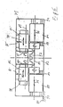
- a machine bed 79 is arranged parallel to a foundation surface or floor surface, which is not described in any more detail.
- two headstocks 80 and 81 are arranged on sliding guides 90 and 91 so as to be displaceable and positionable in an opposing arrangement and with the same axis of rotation or center line 82.
- a workpiece 92 for example a crankshaft, can be picked up and driven in rotation by the workpiece spindles 83 and 84 of these headstocks 80 and 81.
- headstocks 80 and 81 two further headstocks 85 and 86 are arranged, so that each headstock 81 and 80 is assigned a headstock 85 and 86, respectively.
- the headstocks 85 and 86 drive tool carriers 87 and 88 around a common center line 89.
- the tool carrier 87 and 88 can tools z. B. wear according to Figure 4 or Figure 2.
- the workpiece 92 is preferably a crankshaft, as is also indicated in FIG. 2.
- the machine bed 79 can be designed in a U-shape and thereby leave a portal opening 93 centrally.
- This portal opening 93 can leave access to a chip pit.
- the crankshaft can be received by the headstocks 80 and 81 and driven in rotation.
- the crankshaft can then be machined at the desired locations from the tools on the tool carriers 87 and 88, which are not described in any more detail.
- Another possibility of travel can be provided in the direction of arrows 95.
- the headstock 85 or 86 it is only necessary to arrange the headstock 85 or 86 so that it can be displaced and positioned on a carriage (not specified) in the direction of arrows 94.
- This carriage not designated in any more detail, can then be displaced and positioned on guides of the machine bed 79 in the direction of the arrows 95. In this way, the entire machine can be easily adapted to different working conditions.
- a particular advantage is obtained when the machine bed 79 is placed upright in the arrangement according to FIG. 6, so that it forms a portal.
- the foundation is then indicated by line 97.
- the portal opening 97 then allows the workpiece 92 to be freely cycled, perpendicular to the plane of the drawing.
- a chip pit can be provided in the foundation 97, which is also not hindered by the bed 79.
- the machine designs described are relatively easy to set up when considering their respective machining options when using tools with zones free of cutting edges and can nevertheless solve a variety of machining tasks. Non-productive times caused by tool movements that are not used for workpiece machining are minimized. With such machines, the application rate of the machines can be improved and the machine structure itself can be simplified at the same time using the corresponding working method.
Landscapes
- Engineering & Computer Science (AREA)
- Mechanical Engineering (AREA)
- Turning (AREA)
- Milling, Broaching, Filing, Reaming, And Others (AREA)
- Machine Tool Sensing Apparatuses (AREA)
Priority Applications (6)
| Application Number | Priority Date | Filing Date | Title |
|---|---|---|---|
| EP86114599A EP0264474B1 (fr) | 1986-10-21 | 1986-10-21 | Procédé de, et machine pour le brochage par rotation de pièces à symétrie de révolution |
| AT86114599T ATE87522T1 (de) | 1986-10-21 | 1986-10-21 | Verfahren und maschine zum drehraeumen von rotationssymmetrischen werkstuecken. |
| DE8686114599T DE3688196D1 (de) | 1986-10-21 | 1986-10-21 | Verfahren und maschine zum drehraeumen von rotationssymmetrischen werkstuecken. |
| JP62071921A JPH0696206B2 (ja) | 1986-10-21 | 1987-03-27 | 回転対称の工作物の回転ブローチ加工機械 |
| DE8713726U DE8713726U1 (de) | 1986-10-21 | 1987-10-13 | Maschine zum Drehräumen von rotationssymmetrischen Werkstücken |
| US07/109,932 US4799839A (en) | 1986-10-21 | 1987-10-16 | Method and apparatus for performing a rotary broaching operation particularly on work pieces of rotational symmetry |
Applications Claiming Priority (1)
| Application Number | Priority Date | Filing Date | Title |
|---|---|---|---|
| EP86114599A EP0264474B1 (fr) | 1986-10-21 | 1986-10-21 | Procédé de, et machine pour le brochage par rotation de pièces à symétrie de révolution |
Publications (2)
| Publication Number | Publication Date |
|---|---|
| EP0264474A1 true EP0264474A1 (fr) | 1988-04-27 |
| EP0264474B1 EP0264474B1 (fr) | 1993-03-31 |
Family
ID=8195515
Family Applications (1)
| Application Number | Title | Priority Date | Filing Date |
|---|---|---|---|
| EP86114599A Revoked EP0264474B1 (fr) | 1986-10-21 | 1986-10-21 | Procédé de, et machine pour le brochage par rotation de pièces à symétrie de révolution |
Country Status (5)
| Country | Link |
|---|---|
| US (1) | US4799839A (fr) |
| EP (1) | EP0264474B1 (fr) |
| JP (1) | JPH0696206B2 (fr) |
| AT (1) | ATE87522T1 (fr) |
| DE (2) | DE3688196D1 (fr) |
Cited By (1)
| Publication number | Priority date | Publication date | Assignee | Title |
|---|---|---|---|---|
| EP0313644A4 (en) * | 1987-05-13 | 1990-10-10 | Allan J. Heffron | Monotonic cutting machine |
Families Citing this family (11)
| Publication number | Priority date | Publication date | Assignee | Title |
|---|---|---|---|---|
| US5037248A (en) * | 1987-05-13 | 1991-08-06 | Ingersoll Cm Systems Inc. | Cutter for monotonic cutting machine |
| DE3901888A1 (de) * | 1989-01-23 | 1990-08-02 | Boehringer Werkzeugmaschinen | Werkzeugbestueckte drehraeummaschine |
| DE4406272C2 (de) * | 1994-02-25 | 1997-02-27 | Boehringer Werkzeugmaschinen | Werkzeugmaschine zum Drehräumen, Dreh-Drehräumen oder Drehen und Verfahren zur spanenden Bearbeitung von rotationssymmetrischen Werkstücken |
| US6536312B1 (en) * | 1999-05-13 | 2003-03-25 | Komatsu Machinery Corporation | Compound machining center compound machining method and machining tool |
| DE10150710A1 (de) * | 2001-10-13 | 2003-04-17 | Heller Geb Gmbh Maschf | Rotierendes Maschinenelement sowie Verfahren zur Erfassung von Positionswerten von mindestens einem Funktionsträger eines solchen rotierenden Maschinenelementes |
| US20050176251A1 (en) * | 2004-02-05 | 2005-08-11 | Duong Chau H. | Polishing pad with releasable slick particles |
| AT500477A1 (de) | 2004-06-21 | 2006-01-15 | E Hawle Armaturenwerke Gmbh | Ortungs- und betätigungseinrichtung für erdverlegte armaturen |
| JP4867242B2 (ja) * | 2005-09-09 | 2012-02-01 | 横河電機株式会社 | フィールド機器 |
| US20100189526A1 (en) * | 2009-01-23 | 2010-07-29 | Martin Robert M | System and method for broaching a workpiece |
| JP2012131001A (ja) * | 2010-12-22 | 2012-07-12 | Mitsubishi Heavy Ind Ltd | ブローチ加工装置 |
| US9720401B2 (en) * | 2013-12-02 | 2017-08-01 | George Platt | Method and system for consumer home projects ordering and fabrication |
Citations (5)
| Publication number | Priority date | Publication date | Assignee | Title |
|---|---|---|---|---|
| US1579888A (en) * | 1924-12-26 | 1926-04-06 | Ricardo A Raszl | Cutting tool |
| US2173609A (en) * | 1937-10-14 | 1939-09-19 | Leblond Mach Tool Co R K | Combined turning and broaching tool for lathes |
| US2468745A (en) * | 1944-09-23 | 1949-05-03 | John C Garand | Broaching cutter |
| EP0096414A1 (fr) * | 1982-06-07 | 1983-12-21 | Hitachi, Ltd. | Dispositif pour l'usinage d'aube-fixation de turbine |
| DE3340830A1 (de) * | 1983-11-11 | 1985-05-23 | Klaus 5204 Lohmar Allert | Verfahren und vorrichtung zum raeumen der umfangsflaeche eines runden werkstuecks |
Family Cites Families (4)
| Publication number | Priority date | Publication date | Assignee | Title |
|---|---|---|---|---|
| DE2704812C2 (de) * | 1977-02-05 | 1982-10-14 | MTU Motoren- und Turbinen-Union München GmbH, 8000 München | Verfahren zur Herstellung einer Reihe von benachbarten Profilnuten in der Umfangsfläche eines Drehkörpers und Vorrichtung zur Durchführung des Verfahrens |
| JPS5518307A (en) * | 1978-07-17 | 1980-02-08 | Komatsu Ltd | Bite indexing device for boring machine |
| GB2041804B (en) * | 1979-02-13 | 1982-10-20 | Herbert Ltd A | Broaching method and apparatus therefor |
| US4531868A (en) * | 1982-01-19 | 1985-07-30 | Lear Siegler, Inc. | Broaching machine |
-
1986
- 1986-10-21 DE DE8686114599T patent/DE3688196D1/de not_active Revoked
- 1986-10-21 AT AT86114599T patent/ATE87522T1/de not_active IP Right Cessation
- 1986-10-21 EP EP86114599A patent/EP0264474B1/fr not_active Revoked
-
1987
- 1987-03-27 JP JP62071921A patent/JPH0696206B2/ja not_active Expired - Lifetime
- 1987-10-13 DE DE8713726U patent/DE8713726U1/de not_active Expired
- 1987-10-16 US US07/109,932 patent/US4799839A/en not_active Expired - Lifetime
Patent Citations (5)
| Publication number | Priority date | Publication date | Assignee | Title |
|---|---|---|---|---|
| US1579888A (en) * | 1924-12-26 | 1926-04-06 | Ricardo A Raszl | Cutting tool |
| US2173609A (en) * | 1937-10-14 | 1939-09-19 | Leblond Mach Tool Co R K | Combined turning and broaching tool for lathes |
| US2468745A (en) * | 1944-09-23 | 1949-05-03 | John C Garand | Broaching cutter |
| EP0096414A1 (fr) * | 1982-06-07 | 1983-12-21 | Hitachi, Ltd. | Dispositif pour l'usinage d'aube-fixation de turbine |
| DE3340830A1 (de) * | 1983-11-11 | 1985-05-23 | Klaus 5204 Lohmar Allert | Verfahren und vorrichtung zum raeumen der umfangsflaeche eines runden werkstuecks |
Non-Patent Citations (2)
| Title |
|---|
| MASCHINENMARKT, Band 92, Nr. 34, August 1986, Seiten 24-28, Würzburg; M. MÜLLER et al.: "Zerspankraft kompensieren" * |
| PATENT ABSTRACTS OF JAPAN, Band 7, Nr. 279 (M-262)[1424], 13. Dezember 1983; & JP - A - 58 155 125 (HITACHI SEISAKUSHO K.K.) 14.09.1983 * |
Cited By (1)
| Publication number | Priority date | Publication date | Assignee | Title |
|---|---|---|---|---|
| EP0313644A4 (en) * | 1987-05-13 | 1990-10-10 | Allan J. Heffron | Monotonic cutting machine |
Also Published As
| Publication number | Publication date |
|---|---|
| US4799839A (en) | 1989-01-24 |
| EP0264474B1 (fr) | 1993-03-31 |
| JPS63105817A (ja) | 1988-05-11 |
| JPH0696206B2 (ja) | 1994-11-30 |
| ATE87522T1 (de) | 1993-04-15 |
| DE8713726U1 (de) | 1988-01-28 |
| DE3688196D1 (de) | 1993-05-06 |
Similar Documents
| Publication | Publication Date | Title |
|---|---|---|
| DE19711317C2 (de) | Werkzeugmaschine | |
| EP1224048B1 (fr) | Porte-outil | |
| DE3887439T2 (de) | Monotonische schneidevorrichtung. | |
| DE3124606C2 (de) | Geschwindedrehmaschine mit einer Einrichtung zur Schwingungszerspanung | |
| DE2419554A1 (de) | Werkzeugmaschine zur spanabhebenden bearbeitung von wellen, insbesondere von kurbelwellen | |
| EP0264474B1 (fr) | Procédé de, et machine pour le brochage par rotation de pièces à symétrie de révolution | |
| DE1913837C3 (de) | Einstückige Hülse für einen Hochdruckölverteilerschieber und ein Verfahren sowie eine Einrichtung zu ihrer Herstellung | |
| DE2338207A1 (de) | Mehrspindelautomat, insbesondere mehrspindeldrehautomat | |
| DE3941480C2 (fr) | ||
| WO2001094048A1 (fr) | Machine de laminage a froid | |
| EP0214624B1 (fr) | Dispositif pour le brochage d'une surface cylindrique d'une pièce à usiner, de préférence d'un arbre, en particulier d'un arbre coudé | |
| DE3200937C2 (fr) | ||
| DE3434175A1 (de) | Werkzeugmaschine | |
| DE2221872A1 (de) | Einrichtung zur maschinellen bearbeitung von ringfoermigen werkstuecken | |
| WO2005123339A2 (fr) | Meuleuse configuree sous la forme d'une meuleuse cylindrique/non cylindrique universelle | |
| EP0023484B1 (fr) | Decolleteuse a alimentation de barres | |
| DE576655C (de) | Verfahren zum Bearbeiten unregelmaessiger bogenfoermiger Flaechen, wie Nockenflaechen | |
| DE877689C (de) | Rohrbearbeitungsmaschine | |
| DE2226617C2 (fr) | ||
| DE3215394A1 (de) | Maschine fuer die umfangsbearbeitung | |
| EP0178410B1 (fr) | Procédé pour la chanfreinage des extrémités frontales de dents de pièces dentées à usiner et dispositif pour la mise en oeuvre de ce procédé | |
| DE1527172A1 (de) | Einrichtung zum Vorzentrieren zylindrischer Werkstuecke auf einer Gewindeschneidmaschine | |
| EP0119236B1 (fr) | Tour automatique a broches multiples | |
| DE2334667A1 (de) | Honwerkzeug zum aussenhonen von werkstuecken | |
| DE3000055A1 (de) | Maschine zum spanenden bearbeiten ruhender zylindrischer werkstuecke |
Legal Events
| Date | Code | Title | Description |
|---|---|---|---|
| PUAI | Public reference made under article 153(3) epc to a published international application that has entered the european phase |
Free format text: ORIGINAL CODE: 0009012 |
|
| AK | Designated contracting states |
Kind code of ref document: A1 Designated state(s): AT DE FR GB IT |
|
| 17P | Request for examination filed |
Effective date: 19881012 |
|
| 17Q | First examination report despatched |
Effective date: 19891215 |
|
| GRAA | (expected) grant |
Free format text: ORIGINAL CODE: 0009210 |
|
| ITF | It: translation for a ep patent filed | ||
| AK | Designated contracting states |
Kind code of ref document: B1 Designated state(s): AT DE FR GB IT |
|
| REF | Corresponds to: |
Ref document number: 87522 Country of ref document: AT Date of ref document: 19930415 Kind code of ref document: T |
|
| REF | Corresponds to: |
Ref document number: 3688196 Country of ref document: DE Date of ref document: 19930506 |
|
| ET | Fr: translation filed | ||
| GBT | Gb: translation of ep patent filed (gb section 77(6)(a)/1977) |
Effective date: 19930624 |
|
| PLBI | Opposition filed |
Free format text: ORIGINAL CODE: 0009260 |
|
| PLBI | Opposition filed |
Free format text: ORIGINAL CODE: 0009260 |
|
| 26 | Opposition filed |
Opponent name: GEBR. HELLER MASCHINENFABRIK GMBH Effective date: 19931223 |
|
| 26 | Opposition filed |
Opponent name: INGERSOLL CM SYSTEMS, INC. Effective date: 19931231 Opponent name: GEBR. HELLER MASCHINENFABRIK GMBH Effective date: 19931223 |
|
| PGFP | Annual fee paid to national office [announced via postgrant information from national office to epo] |
Ref country code: GB Payment date: 19971013 Year of fee payment: 12 |
|
| PGFP | Annual fee paid to national office [announced via postgrant information from national office to epo] |
Ref country code: AT Payment date: 19971031 Year of fee payment: 12 |
|
| REG | Reference to a national code |
Ref country code: FR Ref legal event code: CD |
|
| PGFP | Annual fee paid to national office [announced via postgrant information from national office to epo] |
Ref country code: DE Payment date: 19971111 Year of fee payment: 12 |
|
| PGFP | Annual fee paid to national office [announced via postgrant information from national office to epo] |
Ref country code: FR Payment date: 19971222 Year of fee payment: 12 |
|
| RDAH | Patent revoked |
Free format text: ORIGINAL CODE: EPIDOS REVO |
|
| APAC | Appeal dossier modified |
Free format text: ORIGINAL CODE: EPIDOS NOAPO |
|
| APAE | Appeal reference modified |
Free format text: ORIGINAL CODE: EPIDOS REFNO |
|
| RAP2 | Party data changed (patent owner data changed or rights of a patent transferred) |
Owner name: HEGENSCHEIDT-MFD GMBH |
|
| APAC | Appeal dossier modified |
Free format text: ORIGINAL CODE: EPIDOS NOAPO |
|
| RDAG | Patent revoked |
Free format text: ORIGINAL CODE: 0009271 |
|
| STAA | Information on the status of an ep patent application or granted ep patent |
Free format text: STATUS: PATENT REVOKED |
|
| 27W | Patent revoked |
Effective date: 19981030 |
|
| GBPR | Gb: patent revoked under art. 102 of the ep convention designating the uk as contracting state |
Free format text: 981030 |
|
| APAH | Appeal reference modified |
Free format text: ORIGINAL CODE: EPIDOSCREFNO |