EP0264477A1 - Procédé de brochage par rotation de pièces sensibles à la flexion ou aux vibrations et machine pour cela - Google Patents
Procédé de brochage par rotation de pièces sensibles à la flexion ou aux vibrations et machine pour cela Download PDFInfo
- Publication number
- EP0264477A1 EP0264477A1 EP86114634A EP86114634A EP0264477A1 EP 0264477 A1 EP0264477 A1 EP 0264477A1 EP 86114634 A EP86114634 A EP 86114634A EP 86114634 A EP86114634 A EP 86114634A EP 0264477 A1 EP0264477 A1 EP 0264477A1
- Authority
- EP
- European Patent Office
- Prior art keywords
- support elements
- machine
- steady rest
- workpiece
- force
- Prior art date
- Legal status (The legal status is an assumption and is not a legal conclusion. Google has not performed a legal analysis and makes no representation as to the accuracy of the status listed.)
- Granted
Links
- 238000000034 method Methods 0.000 title claims abstract description 26
- 238000003754 machining Methods 0.000 claims description 23
- 230000001105 regulatory effect Effects 0.000 claims description 15
- 239000012530 fluid Substances 0.000 claims description 12
- 238000012545 processing Methods 0.000 claims description 8
- 230000007704 transition Effects 0.000 claims description 3
- 238000000465 moulding Methods 0.000 claims 3
- 230000002093 peripheral effect Effects 0.000 abstract 1
- 238000009827 uniform distribution Methods 0.000 abstract 1
- 238000010276 construction Methods 0.000 description 7
- 238000011156 evaluation Methods 0.000 description 3
- 230000006978 adaptation Effects 0.000 description 2
- 238000005452 bending Methods 0.000 description 2
- 238000013461 design Methods 0.000 description 2
- 238000007781 pre-processing Methods 0.000 description 2
- 238000007730 finishing process Methods 0.000 description 1
- 238000009434 installation Methods 0.000 description 1
- 238000007493 shaping process Methods 0.000 description 1
- 238000012546 transfer Methods 0.000 description 1
Images

Classifications
-
- B—PERFORMING OPERATIONS; TRANSPORTING
- B23—MACHINE TOOLS; METAL-WORKING NOT OTHERWISE PROVIDED FOR
- B23Q—DETAILS, COMPONENTS, OR ACCESSORIES FOR MACHINE TOOLS, e.g. ARRANGEMENTS FOR COPYING OR CONTROLLING; MACHINE TOOLS IN GENERAL CHARACTERISED BY THE CONSTRUCTION OF PARTICULAR DETAILS OR COMPONENTS; COMBINATIONS OR ASSOCIATIONS OF METAL-WORKING MACHINES, NOT DIRECTED TO A PARTICULAR RESULT
- B23Q1/00—Members which are comprised in the general build-up of a form of machine, particularly relatively large fixed members
- B23Q1/72—Auxiliary arrangements; Interconnections between auxiliary tables and movable machine elements
- B23Q1/76—Steadies; Rests
Definitions
- the invention relates to a method for rotating broaching workpieces that are sensitive to bending or vibration, and to a machine for carrying out the method.
- Figure 8 shows an arrangement in which the total number of cutting edges is divided into three segments. With a sensible arrangement of the individual indexable inserts on the respective base bodies, this can Configuration the resulting cutting force acting on the crankshaft and the mass forces are compensated. With the construction (Fig. 8) it is also possible to machine unstable workpieces where turning space was previously not possible.
- crankshafts to be machined arrive as blanks and are not sufficiently precisely balanced.
- the resulting mass forces of the crankshafts which are directed radially during the rotation of the workpiece, ensure a circumferential radial force, as a result of which periodically different cutting forces and radial forces arise as a result and reaction force on the individual tools.
- the consequence of this is uncontrolled vibration of the workpiece and the tools as well as unsatisfactory surface quality and dimensional accuracy of the workpiece.
- the invention is therefore based on the object of proposing a method of the type described at the outset which permits reliable machining of an unstable workpiece with tools applied on one side and which at the same time enables simple machine design.
- a suitable machine for carrying out the method is also to be proposed.
- this object is achieved in that a steady rest is formed on at least one point on the workpiece, whereupon an assigned steady rest is created with its supporting elements and the turning-room machining is subsequently continued.
- This makes it possible to pre-process a blank in such a way that a steady rest can be created, which also makes it possible for the first time to stabilize an unstable workpiece in the area of turning broaching in such a way that turning broaching is economically feasible.
- the bezel seat is further processed and the support elements are tracked as the bezel seat becomes smaller.
- this pre-machined area can be finished by the rotary broaching tool with simultaneous further placement of the steady rest.
- the workpiece remains constantly supported and, moreover, is advantageously supported directly in the region of the transverse forces that occur, which are introduced into the workpiece by the tool.
- This procedure is particularly advantageous when machining crankshafts, because it means that the steady rest on the bearing seat, which is also used by the rotary broaching tool is processed, supported.
- the steady rest is in place, the associated bearing seat is finished unhindered by the rotary broaching tool and the steady rest is adjusted.
- a steady rest in the form of a rigid steady rest as well as in the form of a steady rest can avoid the arrangement of several tools distributed around the circumference and simultaneously working on the workpiece. This also avoids the associated design effort for a special machine and the high tool costs are avoided.
- a machine for performing this method can work with tools arranged on one side. These tools can also be converted to different axial positions.
- An adaptation to different axial positions of the locations to be machined on the workpiece can also be done in a simple manner in that the steady rest is arranged so as to be movable in the axial direction on the machine. Overall, this method makes it possible to use machines that can be kept simple in their construction.
- the bezel seat is formed at least at an extended cutting speed and / or reduced feed until the support element is applied.
- a blank can first be prepared so carefully that there is no risk of vibration or deflection. After completing this preparatory work, the bezel can then be put on and finished with normal machine performance.
- a further steady rest seat is formed by the continued machining of the turning space in the area of the steady rest, after which support elements are placed on this further steady rest seat.
- This procedure is particularly advantageous when machining the positions of crankshafts.
- the support can be transferred continuously from one pre-worked area to another pre-worked area. This makes it z. B. possible to edit early First support surfaces and transfer the support to other surface areas that are subsequently processed, if these surfaces that were processed at an early stage completely disappear during the course of processing.
- the first molded bezel seat takes over the entire support.
- the support elements initially come into contact with the other steady rest without supporting force.
- the corresponding support surface moves radially further inwards, which means that the vertical load is transferred to the further steady rest until it finally bears the entire vertical load, because the first molded-on steady rest has been processed far enough.
- first two ring-shaped surfaces and a further ring-shaped surface which is smaller in diameter and arranged between the said surfaces are formed and support elements are applied to the ring-shaped surfaces mentioned before the further turning space machining takes place.
- a special embodiment of the invention provides that the components of the cutting force acting on the support elements in their direction of movement are determined and the support elements are held in contact with the steady rest seat with a corresponding counterforce. This can prevent z. B. the support elements themselves based on their support force cause an undesirable deflection of the workpiece.
- a rotary broaching machine with a device for receiving and driving a workpiece to be machined by rotary broaching, at least one rotary broaching tool that can be brought into working contact with the workpiece, a device for driving the rotary broaching tool and with a machine control are assumed.
- at least one steady rest with support elements which can be placed on pre-machined surfaces of the workpiece is arranged on the machine.
- the bezel has support elements which can be placed on correspondingly pre-machined surfaces of the workpieces. As long as such surfaces are always in exactly the same axial position in the machine, it is sufficient if the support elements of the steady rest can be moved radially and can therefore be applied in the radial direction. However, if the surfaces can occur at axially different locations from workpiece to workpiece, it is additionally necessary that the steady rest can be positioned axially.
- the above-mentioned support elements of the bezel can then be applied to the pre-machined surface by initially positioning the bezel axially and then applying the support elements radially. Here it comes but does not indicate that the movement of the support elements is radial. Rather, it is important that the support elements are applied so that they exert a radially directed force on the pre-machined surface of the workpiece.
- the rotary broaching tool has cutting edges for producing at least one steady rest. This makes it possible to insert a complete blank into the rotary broaching machine without any preprocessing directed towards a steady rest.
- the necessary support surface is then pre-processed in the rotary broaching machine by the appropriately designed rotary broaching tool, so that after this pre-processing there is a correspondingly pre-processed surface on the workpiece against which the support elements of the steady rest can be applied.
- any measures as well as the facilities required to carry out such measures for producing the preprocessed surface outside the rotary broaching machine can be omitted.
- means for tracking the support element with a predetermined or predeterminable force are provided for each support element. This makes it possible to further process the finished surface without hindrance during the installation of the support elements and finally to finish it without the necessary support being lost.
- means for determining the load on the workpiece or tool are provided which are connected to the machine control, which in turn is connected to the means for adjusting or regulating the force for the support elements. This enables a fully automatic adjustment of the support force of the steady rest to the current workpiece load.
- the means for tracking the support elements are connected to the means for adjusting or regulating the force for the support elements in such a way that all means for tracking the support elements are adjusted or regulated together and in the same way. This makes it possible to influence the supporting force in a simple manner.
- the means for tracking assigned to a support element are each connected independently of the corresponding other means to the means for adjusting or regulating the force for the support elements, such that the means assigned to each individual support element are set independently of everything else or can be regulated.
- This makes it possible to influence each individual support element of the bezel in the desired or necessary manner. This may be necessary because the support is supposed to take place in an area in which an assigned tool is machining the workpiece at the same time.
- the support elements of the steady rest cannot therefore completely enclose the workpiece symmetrically, but can only be applied in a partial area of the circumference of the workpiece. This may make it necessary to keep the force of the individual support elements different and to actively influence them.
- the means for tracking the support elements are designed as fluid cylinders. These are easy to control and proven components.
- the means for adjusting or regulating the force for the support elements are designed as a hydraulic circuit for the interference cylinder.
- the regulation of the speed of movement and the force of fluid cylinders is known. This also applies to the components required for this.
- a simply constructed and easily manageable functional assembly is therefore proposed, which can be manufactured using proven components.
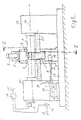
- Headstocks 21 and 22 are arranged in an opposing arrangement on a machine bed 23 which is supported on a foundation, with unspecified, driven spindles, between which a workpiece 1 is clamped. Workpiece 1 can be both clamped and driven by the spindles.
- the drive takes place about the axis of rotation 24.
- the workpiece 1 is machined by a rotary broaching tool 8, which is arranged at least in a rotationally fixed manner on a drive shaft 25 in the necessary axial position.
- the drive shaft 25 can rotate the rotary broaching tool 8 at least at feed rate.
- the corresponding drive for the drive shaft 25 is not shown. However, it must be ensured that the drive shaft 25 is supported or mounted so close to the rotary broaching tool 8 that an inadmissible deflection of this drive shaft 25 does not occur due to the machining forces.
- the illustration of a corresponding tool storage has been omitted in FIG. 2 for reasons of clarity.
- a bezel 3 is further arranged on the machine bed 23 and has three support elements 4 in the exemplary embodiment.
- the support elements 4 can be carried and moved by unspecified piston rods of fluid cylinders 9, 10 and 11 in a suitable arrangement on the steady rest 3.
- the fluid cylinders 9, 10 and 11 are connected to a hydraulic for their actuation and control Lischer circuit 17, which will be described in its construction.
- the steady rest 3 also has a motor 26 which can drive a threaded spindle 27.
- the threaded spindle 27 interacts with a nut 28 provided on the headstock 21 in a stationary manner. If the spindle 27 is rotated via the motor 26, the bezel 3 is hereby displaced in the direction of the axis of rotation 27 on the machine bed depending on the direction of rotation of the spindle 27.
- a machine control 18 is also provided, which provides for the control of the machine and the individual necessary processing sequences in the usual way.
- the machine controller 18 has a central computer (CPU) and an associated data memory. This computer is connected via line 15 to an evaluation device 14, which in turn is connected to a resolver 13 and to a power sensor 12.
- the power sensor 12 determines the power consumption of the motor 20 with which the workpiece spindle is driven.
- the resolver 13 simultaneously determines the speed of the workpiece spindle.
- the workpiece load can be determined in the evaluation device 14 from both data and fed to the machine control 18 and the computer integrated therein via the line 15 already mentioned.
- the computer of the machine control 18 can calculate the necessary support force for the support elements 4 and a pressure control valve 29 in the control line 16 influence hydraulic circuit 17 so that the support elements 4 are applied with appropriate force to a pre-machined steady rest 2 on the workpiece 1.
- pressure oil is supplied via a valve 31 and from there via the pressure control valve 29 via a hydraulic pump 30 driven by a motor and fed to the cylinders 9, 10 and 11 on the side of the cylinder chamber facing away from the piston rod via an unlockable check valve 32.
- the hydraulic pump 30 is secured via a pressure relief valve 33.
- the support elements 4 are thus applied to the steady rest seat 2 with the force preselected on the pressure control valve 29. As a result, a corresponding counterforce that is transmitted from the workpiece to the support elements 4 is compensated. If the force transmitted from the workpiece 1 to the support elements is greater than the force specified by the pressure control valve 29, the support elements 4 are prevented from escaping by the check valve 32, so that a correspondingly increased counterforce builds up in the support elements 4.
- the valve 34 can be switched to the open position via the machine control 18, whereby the unlockable check valve 32 is unlocked, so that a backflow of the flow medium from the cylinders 9, 10 and 11 is possible.
- a backflow into the tank 35 only takes place when the setting for the pressure of the pressure oil specified by the pressure control valve 29 is exceeded.
- the pressure control valve 29 opens a line into the tank 35. This ensures that the support elements 4 are always loaded with a force corresponding to the setting on the pressure control valve 29. This also applies if the pressure control valve 29 is permanently set in its setting by the machine control 18.
- the entire hydraulic circuit 17 is provided in the exemplary embodiment together for all fluid cylinders 9, 10 and 11.
- a workpiece 1 is taken up as a blank by the machine and the drive motor 20 is switched on by supplying power to the power line 19 on the basis of a command from the machine controller 18. Since the machining point on the workpiece 1 and thus the position of the steady rest seat 2 is known, the tool 8 is located at the point necessary for this or is moved there. Likewise, the bezel 3 is moved into the correct position for supporting the workpiece 1 in the axial direction by appropriate operation of the motor 26.
- the end face of the support elements 4 should have a contour along the dash-dotted line in FIG. 3. Furthermore, in FIG. 3, line 6 shows the blank contour of the workpiece 1 in the area in which the machining is to take place.
- the rotary broaching tool 8 first processes the area 2 shown in dashed lines in FIG. 3 at a slow feed rate and with a slow cutting speed of the workpiece 1, so that the end face of each support element 4 can rest there and thus support the workpiece 1.
- the radially further inward end region of the support element 4, with the reference number 7, is free and does not abut the workpiece.
- the steady rest seat 2 moves radially inwards towards the axis of rotation 24 and the support element 4 is correspondingly tracked and thus always remains in contact with the steady rest seat 2.
- a further annular surface 7 ⁇ is machined at the base of the blank, to which in radial direction the Support contour 7 of the support element 4 migrates.
Landscapes
- Engineering & Computer Science (AREA)
- Mechanical Engineering (AREA)
- Turning (AREA)
- Milling, Broaching, Filing, Reaming, And Others (AREA)
- Machine Tool Units (AREA)
- Finish Polishing, Edge Sharpening, And Grinding By Specific Grinding Devices (AREA)
Priority Applications (5)
| Application Number | Priority Date | Filing Date | Title |
|---|---|---|---|
| DE8686114634T DE3685756D1 (de) | 1986-10-22 | 1986-10-22 | Verfahren zur drehraeumen von biegungs- oder schwingungsempfindlichen werkstuecken und maschine hierzu. |
| EP86114634A EP0264477B1 (fr) | 1986-10-22 | 1986-10-22 | Procédé de brochage par rotation de pièces sensibles à la flexion ou aux vibrations et machine pour cela |
| AT86114634T ATE77283T1 (de) | 1986-10-22 | 1986-10-22 | Verfahren zur drehraeumen von biegungs- oder schwingungsempfindlichen werkstuecken und maschine hierzu. |
| JP62077640A JPS63105818A (ja) | 1986-10-22 | 1987-04-01 | 曲げまたは振動に敏感な加工片のブロ−チ削り方法とそのためのブロ−チ盤 |
| DE8713730U DE8713730U1 (de) | 1986-10-22 | 1987-10-13 | Maschine zum Drehräumen von biegungs- oder schwingungsempfindlichen Werkstücken |
Applications Claiming Priority (1)
| Application Number | Priority Date | Filing Date | Title |
|---|---|---|---|
| EP86114634A EP0264477B1 (fr) | 1986-10-22 | 1986-10-22 | Procédé de brochage par rotation de pièces sensibles à la flexion ou aux vibrations et machine pour cela |
Publications (2)
| Publication Number | Publication Date |
|---|---|
| EP0264477A1 true EP0264477A1 (fr) | 1988-04-27 |
| EP0264477B1 EP0264477B1 (fr) | 1992-06-17 |
Family
ID=8195518
Family Applications (1)
| Application Number | Title | Priority Date | Filing Date |
|---|---|---|---|
| EP86114634A Expired - Lifetime EP0264477B1 (fr) | 1986-10-22 | 1986-10-22 | Procédé de brochage par rotation de pièces sensibles à la flexion ou aux vibrations et machine pour cela |
Country Status (4)
| Country | Link |
|---|---|
| EP (1) | EP0264477B1 (fr) |
| JP (1) | JPS63105818A (fr) |
| AT (1) | ATE77283T1 (fr) |
| DE (2) | DE3685756D1 (fr) |
Families Citing this family (1)
| Publication number | Priority date | Publication date | Assignee | Title |
|---|---|---|---|---|
| CN103358141A (zh) * | 2012-03-30 | 2013-10-23 | 昆山诺丹舜蒲胶辊有限公司 | 数控车床轴向可调自动定心中心架 |
Citations (4)
| Publication number | Priority date | Publication date | Assignee | Title |
|---|---|---|---|---|
| CH230535A (de) * | 1940-09-16 | 1944-01-15 | Maschf Augsburg Nuernberg Ag | Verfahren zur Bearbeitung von drehbar gelagerten Werkstücken, z. B. Kurbelwellen, und Maschine zur Ausübung des Verfahrens. |
| FR1403313A (fr) * | 1964-07-10 | 1965-06-18 | Mavilor | Procédé d'usinage de solides de révolution, ainsi que les dispositions de mise en euvre s'y rattachant, et les machines-outils qui en font application |
| DE1477265A1 (de) * | 1963-05-03 | 1969-06-19 | English Electric Co Ltd | Werkzeugmaschinenanordnung |
| DD138745A1 (de) * | 1978-09-13 | 1979-11-21 | Eckart Wlucka | Luenette fuer schwerdrehmaschinen |
Family Cites Families (2)
| Publication number | Priority date | Publication date | Assignee | Title |
|---|---|---|---|---|
| FR2306769A1 (fr) * | 1975-04-11 | 1976-11-05 | Peugeot & Renault | Dispositif pour faciliter l'usinage des manetons de vilebrequins |
| AT373804B (de) * | 1979-10-16 | 1984-02-27 | Gfm Fertigungstechnik | Verfahren und vorrichtung zum fraesen von langen werkstuecken, insbesondere von kurbelwellen od. dgl. |
-
1986
- 1986-10-22 DE DE8686114634T patent/DE3685756D1/de not_active Expired - Lifetime
- 1986-10-22 EP EP86114634A patent/EP0264477B1/fr not_active Expired - Lifetime
- 1986-10-22 AT AT86114634T patent/ATE77283T1/de not_active IP Right Cessation
-
1987
- 1987-04-01 JP JP62077640A patent/JPS63105818A/ja active Granted
- 1987-10-13 DE DE8713730U patent/DE8713730U1/de not_active Expired
Patent Citations (4)
| Publication number | Priority date | Publication date | Assignee | Title |
|---|---|---|---|---|
| CH230535A (de) * | 1940-09-16 | 1944-01-15 | Maschf Augsburg Nuernberg Ag | Verfahren zur Bearbeitung von drehbar gelagerten Werkstücken, z. B. Kurbelwellen, und Maschine zur Ausübung des Verfahrens. |
| DE1477265A1 (de) * | 1963-05-03 | 1969-06-19 | English Electric Co Ltd | Werkzeugmaschinenanordnung |
| FR1403313A (fr) * | 1964-07-10 | 1965-06-18 | Mavilor | Procédé d'usinage de solides de révolution, ainsi que les dispositions de mise en euvre s'y rattachant, et les machines-outils qui en font application |
| DD138745A1 (de) * | 1978-09-13 | 1979-11-21 | Eckart Wlucka | Luenette fuer schwerdrehmaschinen |
Non-Patent Citations (1)
| Title |
|---|
| MASCHINENMARKT, Band 92, Nr. 34, August 1986, Seiten 24-28, Würzburg; M. MÜLLER et al.: "Zerspankraft kompensieren" * |
Also Published As
| Publication number | Publication date |
|---|---|
| DE3685756D1 (de) | 1992-07-23 |
| DE8713730U1 (de) | 1988-01-28 |
| JPH0435284B2 (fr) | 1992-06-10 |
| ATE77283T1 (de) | 1992-07-15 |
| JPS63105818A (ja) | 1988-05-11 |
| EP0264477B1 (fr) | 1992-06-17 |
Similar Documents
| Publication | Publication Date | Title |
|---|---|---|
| DE4237422C2 (de) | Werkstückhaltevorrichtung für auf Werkzeugmaschinen mehrseitig zu bearbeitende Werkstücke | |
| DE19711317C2 (de) | Werkzeugmaschine | |
| DE102009051737B3 (de) | Verfahren zum Schleifen der Haupt- und Hublager einer Kurbelwelle durch Aussenrundschleifen und Schleifmaschine zum Durchführen des Verfahrens | |
| DE1812671A1 (de) | Bohreinrichtung | |
| WO2010054925A1 (fr) | Machine-outil dotée d'un dispositif porteur monté flottant | |
| EP0969945B1 (fr) | Systeme d'avance pour un outil de coupe rotatif | |
| DE3511933A1 (de) | Werkzeugmaschine zur fraes- und drehbearbeitung | |
| DE10303239A1 (de) | Drehschneideinrichtung für eine Kurbelwelle und Verfahren hierfür | |
| DE1286377B (de) | Vorrichtung zur Einstellung der Lagervorspannung einer Werkzeugmaschinenspindel | |
| DE4119162C1 (fr) | ||
| DE69308614T2 (de) | Spannfutter-Indexierungsvorrichtung und Verfahren | |
| EP2076348A1 (fr) | Procédé de verrouillage de pièces utilisées pour la production de roues de compresseur ou de turbine | |
| EP1466684B1 (fr) | Machine-outil pour l'usinage des pièces, en particulier des vilebrequins et des arbres à cames, avec au moins un outil pour le fraisage intérieur | |
| EP0798063A1 (fr) | Outil à aléser | |
| DE4123859A1 (de) | Verfahren zur spanenden bearbeitung von werkstuecken mit rotationssymmetrischen flaechen, vorzugsweise von kurbelwellen, und vorrichtung zur durchfuehrung eines solchen verfahrens | |
| EP0264477B1 (fr) | Procédé de brochage par rotation de pièces sensibles à la flexion ou aux vibrations et machine pour cela | |
| DE3734734C2 (fr) | ||
| DE3345414C1 (de) | Vorrichtung zum Verschwenken einer Werkzeugaufnahmevorrichtung, insbesondere eines Winkelfräskopfes, am freien (unteren) Ende eines Frässpindelschlittens | |
| DE2440123A1 (de) | Spanabhebende werkzeugmaschine, insbesondere schleifmaschine | |
| DE3304463C2 (fr) | ||
| EP3251788B1 (fr) | Dispositif de soutien d'une pièce à usiner | |
| DE10245071B4 (de) | Maschine zum Schruppen und Schlichten der Lagerzapfen von Kurbelwellen | |
| DE3708363A1 (de) | Spannfutter fuer werkzeugmaschinen | |
| DE19722229B4 (de) | Mehrstufige Schmiedemaschine mit einer Mehrzahl von justierbaren Umformstufen | |
| EP3658319B1 (fr) | Outil d'usinage par enlèvement de copeaux et procédé pour l'usinage d'une roulement d'un palier |
Legal Events
| Date | Code | Title | Description |
|---|---|---|---|
| PUAI | Public reference made under article 153(3) epc to a published international application that has entered the european phase |
Free format text: ORIGINAL CODE: 0009012 |
|
| AK | Designated contracting states |
Kind code of ref document: A1 Designated state(s): AT DE FR GB IT |
|
| 17P | Request for examination filed |
Effective date: 19881012 |
|
| 17Q | First examination report despatched |
Effective date: 19891120 |
|
| GRAA | (expected) grant |
Free format text: ORIGINAL CODE: 0009210 |
|
| AK | Designated contracting states |
Kind code of ref document: B1 Designated state(s): AT DE FR GB IT |
|
| REF | Corresponds to: |
Ref document number: 77283 Country of ref document: AT Date of ref document: 19920715 Kind code of ref document: T |
|
| ITF | It: translation for a ep patent filed | ||
| REF | Corresponds to: |
Ref document number: 3685756 Country of ref document: DE Date of ref document: 19920723 |
|
| ET | Fr: translation filed | ||
| GBT | Gb: translation of ep patent filed (gb section 77(6)(a)/1977) | ||
| PLBI | Opposition filed |
Free format text: ORIGINAL CODE: 0009260 |
|
| 26 | Opposition filed |
Opponent name: GEBR. HELLER MASCHINENFABRIK GMBH Effective date: 19930317 |
|
| PGFP | Annual fee paid to national office [announced via postgrant information from national office to epo] |
Ref country code: GB Payment date: 19971013 Year of fee payment: 12 |
|
| PGFP | Annual fee paid to national office [announced via postgrant information from national office to epo] |
Ref country code: FR Payment date: 19971029 Year of fee payment: 12 |
|
| PGFP | Annual fee paid to national office [announced via postgrant information from national office to epo] |
Ref country code: AT Payment date: 19971031 Year of fee payment: 12 |
|
| PGFP | Annual fee paid to national office [announced via postgrant information from national office to epo] |
Ref country code: DE Payment date: 19971111 Year of fee payment: 12 |
|
| REG | Reference to a national code |
Ref country code: FR Ref legal event code: CD Ref country code: FR Ref legal event code: CA |
|
| APAC | Appeal dossier modified |
Free format text: ORIGINAL CODE: EPIDOS NOAPO |
|
| RDAG | Patent revoked |
Free format text: ORIGINAL CODE: 0009271 |
|
| STAA | Information on the status of an ep patent application or granted ep patent |
Free format text: STATUS: PATENT REVOKED |
|
| RAP2 | Party data changed (patent owner data changed or rights of a patent transferred) |
Owner name: HEGENSCHEIDT-MFD GMBH |
|
| 27W | Patent revoked |
Effective date: 19981102 |
|
| GBPR | Gb: patent revoked under art. 102 of the ep convention designating the uk as contracting state |
Free format text: 981102 |
|
| APAH | Appeal reference modified |
Free format text: ORIGINAL CODE: EPIDOSCREFNO |