EP0264492B1 - Rundballenpresse - Google Patents
Rundballenpresse Download PDFInfo
- Publication number
- EP0264492B1 EP0264492B1 EP86201829A EP86201829A EP0264492B1 EP 0264492 B1 EP0264492 B1 EP 0264492B1 EP 86201829 A EP86201829 A EP 86201829A EP 86201829 A EP86201829 A EP 86201829A EP 0264492 B1 EP0264492 B1 EP 0264492B1
- Authority
- EP
- European Patent Office
- Prior art keywords
- bale
- forming means
- baler
- portions
- chamber
- Prior art date
- Legal status (The legal status is an assumption and is not a legal conclusion. Google has not performed a legal analysis and makes no representation as to the accuracy of the status listed.)
- Expired
Links
- 230000033001 locomotion Effects 0.000 claims description 35
- 239000000463 material Substances 0.000 claims description 20
- 230000015572 biosynthetic process Effects 0.000 claims description 18
- 230000005484 gravity Effects 0.000 claims description 9
- 238000006073 displacement reaction Methods 0.000 claims description 6
- 230000008602 contraction Effects 0.000 claims description 2
- 230000000694 effects Effects 0.000 claims description 2
- 238000007599 discharging Methods 0.000 claims 2
- 239000012530 fluid Substances 0.000 description 3
- 230000005540 biological transmission Effects 0.000 description 2
- 230000000903 blocking effect Effects 0.000 description 1
- 239000002184 metal Substances 0.000 description 1
- 238000005086 pumping Methods 0.000 description 1
- 230000000717 retained effect Effects 0.000 description 1
- 230000002441 reversible effect Effects 0.000 description 1
- 230000001360 synchronised effect Effects 0.000 description 1
Images

Classifications
-
- A—HUMAN NECESSITIES
- A01—AGRICULTURE; FORESTRY; ANIMAL HUSBANDRY; HUNTING; TRAPPING; FISHING
- A01F—PROCESSING OF HARVESTED PRODUCE; HAY OR STRAW PRESSES; DEVICES FOR STORING AGRICULTURAL OR HORTICULTURAL PRODUCE
- A01F15/00—Baling presses for straw, hay or the like
- A01F15/08—Details
- A01F15/0825—Regulating or controlling density or shape of the bale
- A01F15/0833—Regulating or controlling density or shape of the bale for round balers
-
- A—HUMAN NECESSITIES
- A01—AGRICULTURE; FORESTRY; ANIMAL HUSBANDRY; HUNTING; TRAPPING; FISHING
- A01F—PROCESSING OF HARVESTED PRODUCE; HAY OR STRAW PRESSES; DEVICES FOR STORING AGRICULTURAL OR HORTICULTURAL PRODUCE
- A01F15/00—Baling presses for straw, hay or the like
- A01F15/07—Rotobalers, i.e. machines for forming cylindrical bales by winding and pressing
- A01F2015/079—Sledge for rollers of the pressing chamber
-
- A—HUMAN NECESSITIES
- A01—AGRICULTURE; FORESTRY; ANIMAL HUSBANDRY; HUNTING; TRAPPING; FISHING
- A01F—PROCESSING OF HARVESTED PRODUCE; HAY OR STRAW PRESSES; DEVICES FOR STORING AGRICULTURAL OR HORTICULTURAL PRODUCE
- A01F15/00—Baling presses for straw, hay or the like
- A01F15/07—Rotobalers, i.e. machines for forming cylindrical bales by winding and pressing
- A01F2015/0795—Pressing chamber with variable volume
Definitions
- This invention relates to roll baling machines which form cylindrical rolls of crop material and which are commonly referred to as round balers.
- EP-A-0161726 there is disclosed a round baler having two sets of bale-forming means which define a bale-forming chamber which is expandable from a small start chamber to a full size chamber.
- one set of bale-forming means is movable with respect to the other set but it has been found that with some crops and/or crop conditions, this is insufficient to ensure that the core of a bale being formed is properly constituted and that the bale is continually rotated during formation. It is highly desirable that the core of a bale being formed has the correct density. It is furthermore essential to ensure that a bale being formed undergoes continual rotation in order that crop material being fed into the machine is taken in and added to the bale. If bale rotation ceases, then further crop material cannot be added to the bale which thus results in the baler becoming blocked.
- a round baler with a bale chamber expandable between a bale start position and a full bale position and comprising a first set of bale-forming means disposed at fixed positions generally circumferentially around a portion of the full size bale chamber when the baler is in its bale-forming condition, and a second set of bale-forming means, which is movable relative to the first set of bale-forming means between two extreme positions; said second set of bale-forming means being cooperable, in one extreme position, with part of the first set of bale forming means to form the bale start chamber of reduced dimensions for starting bale formation, and, in the other extreme position, with all of the first set of bale-forming means to define a generally cylindrical bale chamber generally corresponding to a full size bale and said first and second sets of bale-forming means being cooperable to form a round bale of crop material during movement of the second set of bale-forming means from the one extreme position towards the other extreme position.
- This baler is characterised in that the second set of bale-forming means has linked together at least two portions which also are movable relative to each other; the arrangement being such that, in partially defining the bale-start chamber, adjacent portions of said second set of bale-forming means are inclined relative to each other at an angle which is smaller than the angle pertaining when the second set of bale-forming means partially defines the full size bale chamber.
- the two portions of the second set of bale-flowing means may be pivotal about a common axis with one portion further also being pivotal relative to the other portion; the arrangement being such that said angle between the two portions increases as the bale chamber increases in size during bale formation.
- the two portions of the second set of bale-forming means may be interconnected by means operable to effect said relative movement between the two portions and in a preferred embodiment, said interconnecting means comprise a linkage mechanism having
- the means interconnecting the two portions of the second set of bale-forming means comprise :
- the two portions of the second set of bale-forming means have their movement about said common axis controlled by a hydraulic actuator which may interact with the linkage mechanism interconnecting the two portions of the second set of bale-forming means.
- the hydraulic actuator may be connected to a closed hydraulic circuit comprising a pressure relief valve connected between the ends of the cylinder of the actuator and which is operable to determine the resistance to movement of the second set of bale-forming means about said common axis.
- the pressure relief valve is adjustable in order to vary said resistance to movement and in turn to vary the density of the bale being formed in use of the baler.
- a non-return valve and a restrictor are connected in series with each other and in parallel with the pressure relief valve; the restrictor and the non-return valve being operable to control the operation of the actuator in one direction and the pressure relief valve being operable to control the operation of the actuator in the other direction.
- Movement of the second set of bale-forming means relative to the first set as in use of the baler a bale is being formed is preferably effected by the force applied by said bale being formed on the second set of bale-forming means; this movement effecting contraction of the hydraulic actuator and the second set of bale-forming means returning under gravity to their relative position in which they partially define the start chamber once a formed bale has been discharged from the baler.
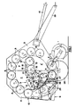
- the baler is generally conventional in that it comprises a crop pick-up mechanism or device 1 which is operable; when the machine is pulled across a field with crop material, to pick up said crop material from the ground and transfer it to the bale-forming chamber 4 of the baler over a bale support and feed roll 2 with retractable feed tines 3.
- the bale chamber 4 is made up of a main frame or front portion 5 and a rear or tailgate portion 6 which is mounted for pivotal movement about a pivot 7 on the main frame 5.
- the pivot 7 extends co-axially with a top roller 8 on the main frame 5 and which forms part of a first and fixed set of rollers 8 spanning both the front and tailgate chamber portions 5 and 6 and disposed generally around a portion of the periphery of a fully formed bale indicated at P.
- the rollers 8 form a first set of bale-forming means, with five of the rollers being disposed in the chamber front portion 5 and three of the rollers in the tailgate portion 6.
- a second set of bale-forming means is provided in the form of two relatively movable portions 9 and 10 with portion 9 having three rollers 11 and portion 10 having two rollers 12.
- This second set of rollers 11, 12 is movable with respect to the first set of rollers 8.
- the rollers 11 are mounted between opposed sidewalls 13 which are interconnected by a pair of transverse beams 14 so as to provide a rigid rectangular framework.
- the rollers 12 are also mounted between opposed sidewalls 15 interconnected by a transverse beam 16, again to provide a rigid framework.
- the portion 10 with the rollers 12 is pivotally mounted with respect to the rollers 11 about a pivot axis which coincides with the axis of rotation of the uppermost roller 11 on the portion 9.
- the frameworks of the two sets of rollers are interconnected by a lug 18 at each side of the machine.
- the lugs 18 pivot at one end around the shaft of said uppermost roller 11 and are attached to the respective sidewalls 15 at the other end.
- the two sets of rollers 11, 12 are also pivotal relative to the rest of the machine about the axis of rotation of the lowermost roller 11 and are further interconnected, at each side of the machine, by a linkage mechanism comprising a link 19 pivotally attached at one end by a pivot 21 to the associated sidewall 15 and pivotally attached at the other end by a pivot 22 to one end of an associated bell crank lever 23.
- Alternative pivot points (not shown) for the pivots 22 slightly displaced from the one shown may be provided in order to vary the shape of the start chamber 4'.
- Each bell crank lever is in the form of a plate 23 pivotally attached at 24 to the associated sidewall 13 and with its effective and respective arms pivotally attached at 25 to one end of a further link 26 and, as already mentioned, at 22 to one end of a link 19.
- the other end of each link 26 is pivotally attached at 27 to the framework of the tailgate portion 6 of the baler.
- a hydraulic actuator is disposed at one side of the baler and has the cylinder 28 thereof pivotally attached at 29 to the framework of the tailgate portion 6 and the piston rod 31 thereof pivotally attached at 32 to the associated sidewall 13 of the lower movable portion 9.
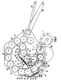
- the hydraulic circuitry associated with the actuator 28, 31 is illustrated in Figure 2 where it can conveniently be shown, and comprises an adjustable relief valve 33 connected across the ends of the cylinder 28. In parallel with the relief valve 33 there is connected, in series with each other, a non-return valve 34 and a fixed restrictor 35, with the common ends of the restrictor 35 and the relief valve 33 being connected to a tank or reservoir 36.
- the hydraulic circuit is a closed system and a pressure gauge 37 is connected to the common junction of the non-return valve 34 and the relief valve 33.
- the single hydraulic actuator 28, 31 may be provided generally centrally thereof between transverse beams forming part of respectively the tailgate framework and the framework of the lower movable portion 9 carrying the rollers 11.
- a pair of such hydraulic actuators 28, 31 may be provided, one at each side, in master and slave relationship.
- the second set of rollers 11, 12 is shown in Figure 1 in full lines in the position adopted at the start of a bale-forming operation so as to define an almost circular (as seen in end view) start chamber 4', and in broken lines in the position adopted when a full size bale P has been formed.
- Figure 2 shows the rollers 11, 12 in an intermediate position, i.e. a position adopted when the start chamber 4' has been expanded but is not yet full size.
- the baler is provided with a pair of ground-engaging wheels 38 and a tongue 39 by which the machine is towed by a tractor or other vehicle.
- the moving components of the baler are driven from the towing vehicle via a conventional power take-off shaft 41.
- the tailgate 6 is closed and the second set of bale-forming rollers 11, 12 is in the full- line position of Figure 1 (i.e. with the actuator 28, 31 extended) so as to define the start chamber 4' of an almost circular cross-section as already described.
- Conventional drive means (not shown) drive the rollers 8, 11 and 12 in the anti clockwise direction as seen in the drawings and as indicated by arrows shown in said drawings.
- the baler is then pulled across a field of cut crop material which is acted upon by the pick-up mechanism 1 and fed to the throat of the start chamber 4' over the feed roller 2.
- the crop material is then passed to the lowermost roller 11 and is moved around the start chamber 4' coming into contact subsequently with the rollers 12, the last one of which throws the crop material onto the two lowermost rollers 8 which are rotating in a direction (as shown in the drawings by the arrows on the rollers) such as to move the crop material back downwardly, thus completing the rotational or coiling motion of the crop material.
- this particular arrangement of the start chamber 4' gives an extremely good core formation with consistent density of the desired magnitude.
- the core is rotated continuously which is not always the case with known balers, as already mentioned, and whereby blockage of the machine, caused by core stalling, is avoided.
- the rollers 8, 11 and 12 which define the start chamber 4' offer a resistance to the expansion of the core as further crop material is added thereto, thus ensuring a required density of that core which is selected by adjusting the throttling action of the relief valve 33.
- the second set of bale-forming rollers 11 and 12 eventually moves in an anticlockwise direction, as seen in Figure 1, whilst still maintaining the resistance required to provide a good bale density. This movement allows the bale being formed in the bale chamber to gradually increase in size as further material is rolled in a spiral pattern on the core.
- This anticlockwise movement of the second set of bale-forming means 9, 10 arises from the fact that the force exerted thereon as the bale increases in size, urges the actuator 28, 31 to gradually contract, thus moving the two portions about the axis of the lowermost roller 11.
- the portion 10 not only moves about the axis of the lowermost roller 11 but also about the axis of the uppermost roller 11, whereby said portion 10 overall rotates through a greater angle than the other portion 9.
- This extra movement of the portion 10 comes about by the link 26 being coupled to the tailgate framework 6 by the pivot 27 whereby the bell crank lever 23 is caused to rotate clockwise around its pivotal mounting 24 on the associated sidewall 13, as seen in Figure 1, as soon as the portion 9 begins to rotate in the anticlockwise direction.
- This clockwise rotation of the bell crank lever 23 pulls the link 19 which in turn pivots the portion 10 about the axis of the uppermost roller 11.
- the bale chamber also expands further and eventually attains its full size 4, i.e. the rollers 11 and 12 adopt the broken line position of Figure 1.
- the links 19 and 26 and the bell crank lever 23 are such that the final movements of the two sets of rollers 11 and 12 to achieve the full size chamber position are accomplished substantially simultaneously.
- the rollers 11 and 12 together with at least some of the rollers 8 and eventually, when the full bale size is reached, all rollers 8 continuously engage the bale surface with a certain pressure which is advantageous for preventing a stalling of the bale under formation.
- the bale being formed is positively kept in rotational motion by a plurality of bale-forming rollers 8, 11, 12 during the entire bale formation cycle. This is advantageous for avoiding a blocking of the machine on the one hand and for obtaining a well-formed bale of high and uniform density on the other hand.
- any completed bale in the bale chamber 4 is wrapped in a conventional manner and, when wrapping has been completed, the tailgate 6 is pivoted upwardly about the axis 7 for the completed bale to be discharged from the machine under gravity.
- the rollers 11, 12 forming the second set of bale-forming means 9, 10 pivot downwardly under gravity about the axis of the lowermost roller 11 thus extending the actuator 28, 31 with the attendant reverse movements of the links 19 and 26 rotation of the bell crank lever 23 and relative rotation of the portions 9 and 10.
- the second set of bale-forming means 11 and 12 is returned in position ready to start the formation of a next bale but before this can be done, the tailgate 6 must be closed or lowered so that the rollers 11 and 12 adopt the position relative to the rollers 8 shown in full lines in Figure 1 so as to re-define the start chamber 4'.
- the lowering or pivoting of the second set of bale-forming means 9, 10 under gravity when the tailgate 6 is opened and the formed bale discharged, is controlled by the restrictor 35 in the hydraulic control circuitry of the actuator 28, 31.
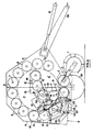
- FIG 3 shows basically an identical machine to that of Figures 1 and 2, i.e. the second set of bale-forming means has two portions which are movable relative to each other. However, the difference lies in the way in which the two portions are urged to move with respect to each other.
- the same reference numerals are used for like components and it will be seen that the portion 10 is pivotally attached to the other portion 9 of the second set of bale-forming means 11-12 and is urged to move relative thereto in an inward direction by way of a spring 42 which acts between one of the beams 14 and the beam 16 on the respective portions 9 and 10 of the second set of bale-forming means.
- the spring 42 is mounted on a threaded rod 43 which is pivotally attached, at one end, to a lug 44 attached to the beam 16 and slidingly received, at the other end, in a pivot 45 provided on one end of a lug 46 which is attached to the said one beam 14; the rod 43 further also carrying a nut 47 by which the spring force is adjustable.
- the spring 42 acts between the nut 47 and an abutment 48 carried by the link 46 and serves to urge the two beams 14 and 16 apart which also means that it also serves to urge the portion 10 of the second set of bale-forming means 11, 12 inwardly, relative to the the portion 9 thereof, as already mentioned.
- An identical hydraulic actuator 28, 31 together with the associated components as shown in Figures 1 and 2 also extends between the tailgate framework 6 and the lower portion 9 of the second set of bale-forming means 11, 12 and operates in precisely the same manner.
- the two 9, 10 portions are urged to be retained in the position in which they adopt for the initial formation of a bale, this position being shown in full lines in Figure 3.
- the core is formed in the same way as described with respect to Figures 1 and 2, with rotation of the core being effected in as good a manner as previously.
- the two portions 9 and 10 of the second set of bale-forming means pivot anticlockwise about the axis of the lowermost roller 11 against the resistance of the actuator 28, 31 which is now starting to contract.
- the portion 10 also pivots relative to the portion 9 about the axis of the uppermost roller 11 against the action of the spring 42 because the resistances offered by the actuator 28, 31 and the spring 42 are attuned to each other to guarantee these synchronized movements.
- the two portions 9 and 10 of the second set of bale-forming means move both relative to each other and together in the desired manner, and generally similarly to that of the first embodiment, until they reach the full bale position again, achieving this position generally simultaneously.
- the spring 42 will be compressed to its maximum. It will be appreciated that the spring arrangement will allow the rollers 12 of the second set of bale-forming means to pivot independently of the other set 11 if in fact the resistances offered by the spring 42 and the actuator 28, 21 are not attuned to each other, although desirably, the two pivotal movements take place generally simultaneously as already described.
- FIG 4 shows a baler having a spring 42 and rod 43 interconnecting the two portions 9 and 10 as in Figure 3, rather than a linkage mechanism 19, 26 as in Figures 1 and 2.
- the difference between Figures 3 and 4 is that in Figure 3 the second set of bale-forming means 11, 12 is provided in the tailgate 6 (as in Figure 1), but in Figure 4, the second set is provided in the front portion 5 of the bale chamber.
- the tailgate mounting or positioning of this second set of bale-forming means 11, 12 (as in Figures 1, 2 and 3) is preferred but it is feasible to adopt the arrangement of Figure 4.
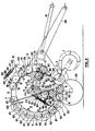
- drive means are shown for driving the various rollers 8, 11 and 12; these drive means being in the form of first gears 61 on the roller shafts and intermediate gears 62 meshing with the first gears 61 of adjacent rollers so as to transmit driving power from one roller to the next adjacent roller.
- the rollers 11 of the second set of bale-forming means receive driving power from the PTO 41 via further drive transmission means (not shown) and the lowermost roller 11 coinciding with the pivotal mounting of the portion 9.
- rollers 8 in the tailgate 6 also receive motive power via sprocket 61 coinciding with the tailgate pivot 7; this sprocket itself receiving power from the PTO 41 via further drive means (not shown).
- These drive train arrangements do not interfere with the pivotal mountings of respectively the portion 9 on the mainframe 5, the portion 10 on the portion 9 and the tailgate 6 on the mainframe 5 as will be readily understood. Similar drive arrangements may be used in the embodiments shown in Figures 1, 2 respectively 3.
- FIG 5 there is shown a further alternative embodiment in which the spring 42 of Figures 3 and 4 is dispensed with and the necessary controlled movements of the two portions 9 and 10 of the second set of bale-forming means are effected using a single actuator 28, 31 with a linkage mechanism.
- This arrangement is in fact a compromise between the embodiment of Figures 1 and 2 and the embodiments of Figures 3 and 4 in as much as in Figures 1 and 2 the relative movement of the two portions 9, 10 of the second set of bale-forming means is fully controlled by the linkage mechanism 19, 23, 26 described, whereas in the embodiments of Figures 3 and 4, this relative movement can be varied depending on the relative settings (resistances) of the acutator 28, 31 and spring 42.
- the piston 31 When the second set of bale-forming means 9, 10 is in the bale start position, the piston 31 is fully extended relative to the cylinder 28, as in the previous embodiments, and as the second set of bale-forming means start pivoting under the action of the increasing size of the bale, the piston 31 is forced into the cylinder as before. This movement is effected through the links 52 and 55, the portion 10 of the second set of bale-forming means pivoting relative to the portion 9 about the axis of the uppermost roller 11 and both portions pivoting about the axis of the lowermost roller 11, as before.
- the two sets of rollers 11, 12 finally adopt the full bale position as in the previous embodiments.
- any given angular displacement of the lower portion 9 around the axis of the lower roller 11 necessarily results in a predetermined angular displacement of the upper portion 10 around the axis of the upper roller 11 which depends solely on the transmission ratio of the linkage means 16, 23, 26.
- both portions 9, 10 pivot generally proportionally and in a manner to continuously define, together with at least some of the rollers 8 a bale-forming chamber 4', 4 which is as close as possible to a fully cylindrical shape.
- the bale being formed in this chamber is continuously rotated whereby it is generally cylindrically shaped during its formation.
- the hydraulic circuitry 28, 31, 33 and the spring 42 urge the respective portions 9 and 10 into engagement with the bale in the bale chamber and thus, said portions 9 and 10 indeed pivot generally proportionally in the way as described, during operation.
- the present invention accomplishes good bale formation and density without machine blockage problems and that the bale density can be adjusted as required by varying the setting fo the relief valve 33.
- the enhanced formation of the core of the bale is achieved by the ability of the two portions 9, 10 of the second set of bale-forming means to move relative to each other as well as in unison as the bale increases in size, the smaller angle between the two portions at the commencement of bale formation enabling a better shape of start chamber 4', as seen in cross-section, to be achieved.
- the second set of bale-forming means 11, 12 has only two portions which are movable relative to each other
- the second set of bale-forming means has a larger number (e.g. three, four...) of relatively movable portions.
- This larger number of relatively movable portions is arranged in such a manner that, in the bale start position, the adjacent portions of any one pair of adjacent portions are inclined relative to each other at an angle which is smaller than the angle pertaining when the second set of bale-forming means is positioned in the full bale position.
- each portion thus is individually pivoted off the preceding portion, i.e.
- bale-forming means in each of the movable portions may be formed by one or more rollers of the type such as used in the embodiments according to Figures 1-5.
- the bale-forming means of the outermost portion i.e. the portion furthest away from the common pivot axis on either the bale chassis or the tailgate
- bale starting chamber may be obtained which is even closer to a cylindrical shape than is the case with the various arrangements shown in the drawings.
Landscapes
- Life Sciences & Earth Sciences (AREA)
- Environmental Sciences (AREA)
- Storage Of Harvested Produce (AREA)
Claims (17)
Priority Applications (3)
| Application Number | Priority Date | Filing Date | Title |
|---|---|---|---|
| DE8686201829T DE3668749D1 (de) | 1986-10-21 | 1986-10-21 | Rundballenpresse. |
| EP86201829A EP0264492B1 (de) | 1986-10-21 | 1986-10-21 | Rundballenpresse |
| US07/111,379 US4765237A (en) | 1986-10-21 | 1987-10-20 | Round baler with expandable bale chamber |
Applications Claiming Priority (1)
| Application Number | Priority Date | Filing Date | Title |
|---|---|---|---|
| EP86201829A EP0264492B1 (de) | 1986-10-21 | 1986-10-21 | Rundballenpresse |
Publications (2)
| Publication Number | Publication Date |
|---|---|
| EP0264492A1 EP0264492A1 (de) | 1988-04-27 |
| EP0264492B1 true EP0264492B1 (de) | 1990-02-07 |
Family
ID=8195812
Family Applications (1)
| Application Number | Title | Priority Date | Filing Date |
|---|---|---|---|
| EP86201829A Expired EP0264492B1 (de) | 1986-10-21 | 1986-10-21 | Rundballenpresse |
Country Status (3)
| Country | Link |
|---|---|
| US (1) | US4765237A (de) |
| EP (1) | EP0264492B1 (de) |
| DE (1) | DE3668749D1 (de) |
Families Citing this family (14)
| Publication number | Priority date | Publication date | Assignee | Title |
|---|---|---|---|---|
| DE3941707A1 (de) * | 1989-12-18 | 1991-06-20 | Claas Ohg | Rundballenpresse fuer halmfoermiges erntegut |
| IT1277868B1 (it) * | 1995-07-24 | 1997-11-12 | Antonio Feraboli | Rotopressa per la raccolta e la formazione di balle cilindriche di foraggio o paglia, del tipo a camera variabile, con camera di |
| DE19624718C2 (de) * | 1996-06-21 | 2002-10-31 | Claas Kgaa Mbh | Rundballenpresse |
| DE29706544U1 (de) * | 1997-04-11 | 1997-06-05 | Greenland Geldrop B.V., Geldrop | Rundballenpresse |
| US6098391A (en) * | 1998-05-08 | 2000-08-08 | New Holland North America, Inc. | Round bale forming apparatus |
| DE29812262U1 (de) * | 1998-07-09 | 1998-09-10 | Greenland Geldrop B.V., Geldrop | Rundballenpresse |
| DE29814775U1 (de) * | 1998-08-18 | 1998-11-12 | Usines Claas France, Woippy | Rundballenpresse |
| US7337603B2 (en) * | 2004-03-12 | 2008-03-04 | Duratech Industries International, Inc. | Round baler leaf reclamation device |
| US20050198934A1 (en) * | 2004-03-12 | 2005-09-15 | Duratech Industries International, Inc. | Round baler reclamation belt |
| US7574955B2 (en) | 2007-06-29 | 2009-08-18 | Cnh America Llc | Two position bale forming roll |
| US20100077716A1 (en) * | 2008-09-26 | 2010-04-01 | Sonne Randy D | Baler with hydraulic clutch |
| NL2012073C2 (en) * | 2014-01-10 | 2015-07-13 | Forage Innovations Bv | Baling device to form bales of loose material having a hybrid baling chamber construction. |
| KR101714327B1 (ko) * | 2016-07-28 | 2017-03-09 | 주식회사 명성 | 구동기어가 적용된 베일형성장치 |
| US20250261592A1 (en) * | 2024-02-21 | 2025-08-21 | Cnh Industrial America Llc | Adjustable sledge for round baler |
Family Cites Families (9)
| Publication number | Priority date | Publication date | Assignee | Title |
|---|---|---|---|---|
| US3931702A (en) * | 1974-07-17 | 1976-01-13 | Deere & Company | Machine for forming cylindrical hay bales |
| DE2626263C2 (de) * | 1976-06-11 | 1983-04-28 | Maschinenfabrik Fahr Ag Gottmadingen, 7702 Gottmadingen | Wickelpresse zum Herstellen von Ballen aus landwirtschaftlichem Halmgut, insbesondere Heu |
| US4288971A (en) * | 1980-04-02 | 1981-09-15 | Sperry Corporation | Round baler |
| GB2090560B (en) * | 1980-12-09 | 1985-10-02 | Brockdale Developments Ltd | Agricultural baling machine |
| NL8304136A (nl) * | 1983-12-01 | 1985-07-01 | Texas Industries Inc | Inrichting voor het vormen van balen gewas. |
| NL191643C (nl) * | 1984-01-16 | 1995-12-02 | Lely Nv C Van Der | Inrichting voor het vormen van cilindervormige balen gewas. |
| EP0161726B1 (de) * | 1984-05-18 | 1990-07-18 | Ford New Holland N.V. | Rundballenpresse |
| US4566379A (en) * | 1984-05-18 | 1986-01-28 | Sperry Corporation | Round baler with vertically elongated starting chamber |
| US4698955A (en) * | 1986-02-18 | 1987-10-13 | Wagstaff Robert A | Bale density control system for round balers |
-
1986
- 1986-10-21 DE DE8686201829T patent/DE3668749D1/de not_active Expired - Lifetime
- 1986-10-21 EP EP86201829A patent/EP0264492B1/de not_active Expired
-
1987
- 1987-10-20 US US07/111,379 patent/US4765237A/en not_active Expired - Fee Related
Also Published As
| Publication number | Publication date |
|---|---|
| EP0264492A1 (de) | 1988-04-27 |
| DE3668749D1 (de) | 1990-03-15 |
| US4765237A (en) | 1988-08-23 |
Similar Documents
| Publication | Publication Date | Title |
|---|---|---|
| EP0264492B1 (de) | Rundballenpresse | |
| EP0264497B2 (de) | Ballenaustragvorrichtung für landwirtschaftliche Presse | |
| US4262478A (en) | Agricultural machine | |
| EP2661953B1 (de) | Akkumulatorsystem für die Bandvorspannung einer Rundballenpresse | |
| US7640852B1 (en) | Round baler belt-tensioning cylinder arrangement also used for bale ejection | |
| US9295198B2 (en) | Density system bypass for a round baler | |
| US4433619A (en) | Method for unplugging cylindrical baler | |
| US4391187A (en) | Belt-tensioning system for round balers | |
| US5367865A (en) | Round baler apron tensioning apparatus | |
| US4702066A (en) | Round baler with automatic steering system | |
| US4545298A (en) | Cylindrical baler hydraulic circuit for controlling bale chamber tension and operating bale discharge gate | |
| EP1588605B1 (de) | Rundballenpresse | |
| US4259035A (en) | Agricultural bale accumulator | |
| EP1588604B1 (de) | Rundballenpresse | |
| US6994020B2 (en) | Large round baler | |
| US4765238A (en) | Round baler with expanding bale chamber | |
| EP0364042B1 (de) | Riemenspannungsvorrichtung für eine Rundballenpresse | |
| EP0309938A1 (de) | Rundballenpresse mit kontinuierlicher Herstellung und Sammleranhänger | |
| CA1227694A (en) | Cylindrical baler hydraulic circuit for controlling bale chamber tension and operating bale discharge gate | |
| US5839362A (en) | Single cylinder hydraulic tension control system for round balers | |
| EP0293621A1 (de) | Seilspende-Mechanismus | |
| EP0206889B1 (de) | Vorrichtung auf einer Rundballenpresse zum Auswerfen der Ballen | |
| US3934393A (en) | Breakaway mechanism for an improved crop material roll forming machine | |
| US12336457B2 (en) | Auxiliary pressure circuit for a round baler | |
| EP0057843B1 (de) | Ballenpresse |
Legal Events
| Date | Code | Title | Description |
|---|---|---|---|
| PUAI | Public reference made under article 153(3) epc to a published international application that has entered the european phase |
Free format text: ORIGINAL CODE: 0009012 |
|
| 17P | Request for examination filed |
Effective date: 19861021 |
|
| AK | Designated contracting states |
Kind code of ref document: A1 Designated state(s): DE FR GB |
|
| RAP3 | Party data changed (applicant data changed or rights of an application transferred) |
Owner name: FORD NEW HOLLAND N.V. |
|
| 17Q | First examination report despatched |
Effective date: 19890130 |
|
| GRAA | (expected) grant |
Free format text: ORIGINAL CODE: 0009210 |
|
| AK | Designated contracting states |
Kind code of ref document: B1 Designated state(s): DE FR GB |
|
| REF | Corresponds to: |
Ref document number: 3668749 Country of ref document: DE Date of ref document: 19900315 |
|
| ET | Fr: translation filed | ||
| PLBE | No opposition filed within time limit |
Free format text: ORIGINAL CODE: 0009261 |
|
| STAA | Information on the status of an ep patent application or granted ep patent |
Free format text: STATUS: NO OPPOSITION FILED WITHIN TIME LIMIT |
|
| 26N | No opposition filed | ||
| REG | Reference to a national code |
Ref country code: GB Ref legal event code: IF02 |
|
| REG | Reference to a national code |
Ref country code: FR Ref legal event code: CD |
|
| PGFP | Annual fee paid to national office [announced via postgrant information from national office to epo] |
Ref country code: GB Payment date: 20040924 Year of fee payment: 19 |
|
| PGFP | Annual fee paid to national office [announced via postgrant information from national office to epo] |
Ref country code: FR Payment date: 20041006 Year of fee payment: 19 |
|
| PGFP | Annual fee paid to national office [announced via postgrant information from national office to epo] |
Ref country code: DE Payment date: 20041013 Year of fee payment: 19 |
|
| PG25 | Lapsed in a contracting state [announced via postgrant information from national office to epo] |
Ref country code: GB Free format text: LAPSE BECAUSE OF NON-PAYMENT OF DUE FEES Effective date: 20051021 |
|
| PG25 | Lapsed in a contracting state [announced via postgrant information from national office to epo] |
Ref country code: DE Free format text: LAPSE BECAUSE OF NON-PAYMENT OF DUE FEES Effective date: 20060503 |
|
| GBPC | Gb: european patent ceased through non-payment of renewal fee |
Effective date: 20051021 |
|
| PG25 | Lapsed in a contracting state [announced via postgrant information from national office to epo] |
Ref country code: FR Free format text: LAPSE BECAUSE OF NON-PAYMENT OF DUE FEES Effective date: 20060630 |
|
| REG | Reference to a national code |
Ref country code: FR Ref legal event code: ST Effective date: 20060630 |