EP0264511A1 - Videokamera zur Untersuchung von Bohrlöchern - Google Patents
Videokamera zur Untersuchung von Bohrlöchern Download PDFInfo
- Publication number
- EP0264511A1 EP0264511A1 EP86402369A EP86402369A EP0264511A1 EP 0264511 A1 EP0264511 A1 EP 0264511A1 EP 86402369 A EP86402369 A EP 86402369A EP 86402369 A EP86402369 A EP 86402369A EP 0264511 A1 EP0264511 A1 EP 0264511A1
- Authority
- EP
- European Patent Office
- Prior art keywords
- wall
- cylindrical
- window
- cavity
- borehole logging
- Prior art date
- Legal status (The legal status is an assumption and is not a legal conclusion. Google has not performed a legal analysis and makes no representation as to the accuracy of the status listed.)
- Withdrawn
Links
Images


Classifications
-
- E—FIXED CONSTRUCTIONS
- E21—EARTH OR ROCK DRILLING; MINING
- E21B—EARTH OR ROCK DRILLING; OBTAINING OIL, GAS, WATER, SOLUBLE OR MELTABLE MATERIALS OR A SLURRY OF MINERALS FROM WELLS
- E21B47/00—Survey of boreholes or wells
- E21B47/002—Survey of boreholes or wells by visual inspection
Definitions
- the present invention is directed to a borehole video camera for inspecting the inner wall of a substantially cylindrical cavity, and in particular for viewing from a remote location the wall of a borehole or the inner surface of a well casing.
- a borehole is drilled up to certain depth into the earth, it may be desirable to inspect the walls of the borehole in order to collect valuable information concerning the geological formations traversed by said borehole. Also, monitoring of the inner surface of the casing placed in the borehole may also be extremely valuable in detecting corrosion and cracks and checking the effectiveness of production perforations.
- US-A-2,912,495 describes a device for viewing oil well borehole comprising a television camera pointing towards a conical mirror coaxial with the longitudinal axis of the borehole.
- a light source illuminates the wall of the borehole, the light being reflected back via the conical mirror towards the television camera.
- Figures 6 to 8 of US-A-3,279,085 which describes a similar device making use of spherical mirror instead of a conical mirror illustrate very well the view obtained with such known devices. It will easily be understood that any longitudinal movement of the camera inside the cylindrical cavity will cause the outer part of the view to shrink towards the center part of the view, thus requiring extensive processing for reconstructing an undistorted image.
- the view is a perspective view which does not reflect the true dimensions, in other words the view is distorted.
- the object of the invention is to obtain a high resolution undistorted view of the inner wall of a substantially cylindrical cavity.
- a borehole logging camera for viewing the inner wall of a substantially cylindrical cavity comprises a longitudinal housing which includes a cylindrical transparent window and which is adapted to receive therein: - means for illuminating the inner wall of the cavity opposite said window; - reflecting means placed opposite said window and whose reflecting area is axisymmetric in order to reflect the radially impinging image of the inner wall of the cavity substantially in the direction of the longitudinal axis of said cylindrical window; - focusing means for focusing the image reflected by said reflecting means; - a plurality of photosensitive elements arranged in an annular array and responsive to the image received from said focusing means.
- annular array of photosensitive elements advantageously reduces the amount of data to be transmitted to the remote location via the borehole logging cable whose length may typically reach 8000 meters. Such a reduction also allows the use of small diameter logging cable (i.e. a two electrical conductor cable) which is particularly well suited for use in gas wells under high wellhead pressure.
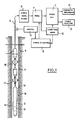
- a downhole logging device 1 is suspended at the end of a cable 2 in a borehole 3 fitted with a casing 4 and traversing underground formations 5.
- the cable 2 is connected to a surface cable correction filter 6 for amplifying, correcting and adapting the signals coming up hole prior being fed into a processing unit 7.
- the processing unit includes an analog to digital converter, random access memories and a digital to analog converter (not shown) and is driven by the timing and control circuit 8 into which the pulses of a depth encoder system 9 are fed.
- the video part comprises the video time base 10 and the video mix circuit 11 which delivers appropriate signals to a magnetic recorder 12 and a video monitor 13.
- the downhole logging device 1 comprises as pressure resistant housing 14 inside which the camera assembly 15 and the corresponding electronic circuitry 16 are located. Part of the housing 14 is made of a cylindrical window 16 transparent to light. Said window is preferably made of high strength glass.
- the downhole logging device is centered in the casing by means of suitable well known centering devices 17 and 18.
- FIG 2 illustrates the optical principle of the camera according to the invention.
- the light for illuminating the inner wall 20 of the casing 4 is provided by means of an halogen bulb 19 placed inside the housing 14.
- the light emitted by the bulb 19 is focused through a yellow band-pass filter 21 into a bundle 22 of fiber optic cables.
- the bundle 22 is split into three strands 24 (only one being shown) which are routed around the substrate 23 carrying the photosensitive elements 41 and then recombined as one hollow cylindrical bundle 25 around a cylindrical aluminum sheath 26 which extends up to the transparent window 16.
- the aluminum sheath 26 acts as a shield against direct light interferences between the cylindrical fiber optic bundle 25 and the photodiode substrate 23.
- the cylindrical fiber optic bundle 25 shines out onto an annular prism mirror 27 which reflects radially the light energy through the window 16 towards the inner wall 20 of the casing 4.
- the image reflected back by the inner wall 20 of casing 4 converges radially through the window 16 onto a hemispherical mirror 28 centered inside the window 16 whose axis is represented by zz ⁇ .
- Mirror 28 is adapted to reflect the impinging image towards a lens 29 which will focus the beams onto the respective individual photodiodes 41 of the substrate 23. While a substantially hemispherical form of the reflecting area of mirror 28 is preferred, it will be understood that any conical area or any other axisymmetrical area whose axis is aligned with axis zz ⁇ can possibly be used.
- FIG 3 represents a front view of the substrate 23 carrying the photosensitive elements 41 which are preferably photodiodes.
- Substrate 23 comprises an annular array 40 of photodiodes 41, each photodiode being responsive to the reflection from a corresponding elementary area of the inner wall 20 of the casing 4.
- Such substrates are available on the market with an annular array of 720 photodiodes, thus giving an azimuthal resolution of half a degree.
- Figure 4 represents the bloc diagram of the downhole electronic circuitry.
- the signal of a pixel oscillator 50 is fed into a time base circuit 51 which delivers suitable signals to the clock drivers 52.
- the photodiodes 41 of the substrate 23 are scanned every 25 ms with a read out time of 2 ms.
- This signal is fed into an differential amplifier 53 , then combined with a synchronization pulse in a samp le/hold circuit 54.
- a cable correction filter 55 boosts the signal before being fed into cable 2 by the cable drive circuit 56.
- Figure 5 and cross-sectional view shown in Fig. 6 illustrate an embodiment of the invention particularly well suited for boreholes where the ambient temperature may often be above 100° C.
- the light source 119, the lens 121 and the fiber optic bundle 122 are carried by a cylindrical support 100 which is located inside the pressure resistant housing 114.
- the support member 101 carrying the lens 121 acts as a thermal shield in order to prevent heat transfer from the source 119 towards the photodiode substrate 123.
- the photodiode substrate 123 Located inside a thermal flask 102, the photodiode substrate 123 is mounted with its face parallel to the axis zz ⁇ of the cylindrical window 116 and is facing a prism mirror 103.
- the mirror 103 is mounted on a support member 113 and reflects at a right angle the image received from the focusing lens 129 towards the photodiode substrate 123.
- a cylindrical extension 126 of the thermal flask 102 acts as a shield against direct light interferences between the cylindrical fiber optic bundle 125 and the photodiode substrate 123.
- the cylindrical extension 126 does also support the annular prism mirror 127 which illuminates the well casing (not shown in figure 5).
- the photodiode substrate 123 is mounted on thermoelectric elements 104 which are adapted to regulate the temperature inside the thermal flask 102.
- the elements 104 are dynamically controlled by a thermometer (not shown) placed on the face of the substrate 123, the Peltier current being adjusted to maintain the temperature of the substrate below 70 ° C.
- a heat sink 105 evacuates the thermal energy to the borehole fluid via the housing 114.
- Such a temperature regulating system allows to operate the camera at an outside temperature of about 125° C, while maintaining substantially constant, over a wide temperature range, the response of the camera.
- the electric wiring 110 of photodiodes 141 and Peltier elements 104 traverses the thermal flask 102 and the support member 101 by means of suitable connectors or thermal packings 111 and 112.
- the cylindrical glass window 116 is sealingly mounted at the end of the housing 114 by means of a threaded nut 106.
- the other end of the window is sealingly provided with a bottom pressure resistant plug 107 by means of threaded nut 108.
- Glass window 116 has to withstand the pressure of the surrounding medium which typically can reach a few hundred bar.
- the hemispherical mirror 128 is carried by the plug 107, its position being adjustable by means of a screw 109 which allows proper optical matching.
- the use of a hemispherical mirror advantageously renders the optical alignment of the mirror 128 with the focusing lens 129 much simpler.
- the overall magnification of the above described optical system is a function of pipe size and ranges from approximately 2.5 in a 60 mm diameter pipe to 1 in a 160 mm diameter pipe.
- the optical configuration yields a depth of field of 30 mm to 90 mm radius, thus avoiding additional adjustable focusing means.
- the azimuthal resolution is half a degree, the vertical resolution of the camera being around l mm.
Landscapes
- Physics & Mathematics (AREA)
- Life Sciences & Earth Sciences (AREA)
- Engineering & Computer Science (AREA)
- Geology (AREA)
- Mining & Mineral Resources (AREA)
- Geophysics (AREA)
- Environmental & Geological Engineering (AREA)
- Fluid Mechanics (AREA)
- General Life Sciences & Earth Sciences (AREA)
- Geochemistry & Mineralogy (AREA)
- Investigating Materials By The Use Of Optical Means Adapted For Particular Applications (AREA)
- Geophysics And Detection Of Objects (AREA)
Priority Applications (1)
| Application Number | Priority Date | Filing Date | Title |
|---|---|---|---|
| EP86402369A EP0264511A1 (de) | 1986-10-23 | 1986-10-23 | Videokamera zur Untersuchung von Bohrlöchern |
Applications Claiming Priority (1)
| Application Number | Priority Date | Filing Date | Title |
|---|---|---|---|
| EP86402369A EP0264511A1 (de) | 1986-10-23 | 1986-10-23 | Videokamera zur Untersuchung von Bohrlöchern |
Publications (1)
| Publication Number | Publication Date |
|---|---|
| EP0264511A1 true EP0264511A1 (de) | 1988-04-27 |
Family
ID=8196349
Family Applications (1)
| Application Number | Title | Priority Date | Filing Date |
|---|---|---|---|
| EP86402369A Withdrawn EP0264511A1 (de) | 1986-10-23 | 1986-10-23 | Videokamera zur Untersuchung von Bohrlöchern |
Country Status (1)
| Country | Link |
|---|---|
| EP (1) | EP0264511A1 (de) |
Cited By (9)
| Publication number | Priority date | Publication date | Assignee | Title |
|---|---|---|---|---|
| EP0643198A3 (de) * | 1990-06-15 | 1995-05-31 | Westech Geophysical Inc | Videomesssystem mit auf Abstand gelegener Energieversorgung. |
| US5790185A (en) * | 1996-12-06 | 1998-08-04 | Auzerais; François | Video inspection or logging tool |
| WO1999060249A1 (en) | 1998-05-19 | 1999-11-25 | Proneta Ltd. | Imaging sensor |
| WO2002006631A1 (en) * | 2000-07-18 | 2002-01-24 | Dhv International, Inc. | Borehole inspection videocamera |
| GB2399971B (en) * | 2003-01-22 | 2006-07-12 | Proneta Ltd | Imaging sensor optical system |
| EP1867833A1 (de) | 2006-06-15 | 2007-12-19 | Services Pétroliers Schlumberger | Vorrichtung und Verfahren zur Darstellung von Bildern einer Bohrlochwand |
| EP2317072A1 (de) * | 2009-10-30 | 2011-05-04 | Welltec A/S | Blasen-Erfassungswerkzeug |
| US10009526B2 (en) | 2014-02-13 | 2018-06-26 | Ut-Battelle, Llc | Apparatus and methods for imaging interior surfaces of a tube or the like |
| US11473418B1 (en) | 2020-01-22 | 2022-10-18 | Vermeer Manufacturing Company | Horizontal directional drilling system and method |
Citations (6)
| Publication number | Priority date | Publication date | Assignee | Title |
|---|---|---|---|---|
| US2912495A (en) * | 1956-02-03 | 1959-11-10 | Moon James | Device for viewing oil well bore hole |
| DE2104095A1 (de) * | 1971-01-29 | 1972-08-10 | Eltro Gmbh | Einrichtung zur Abkühlung eines IR-Detektors |
| US3974330A (en) * | 1975-06-09 | 1976-08-10 | Sperry Rand Corporation | Miniature underwater bore hole inspection apparatus |
| GB2047882A (en) * | 1979-02-27 | 1980-12-03 | Diffracto Ltd | Determinationa of physical characteristics of surfaces |
| US4317632A (en) * | 1979-10-19 | 1982-03-02 | Electric Power Research Institute, Inc. | Method and means for optical inspection of the interior surface of tubing |
| DE3213652A1 (de) * | 1982-04-14 | 1983-10-27 | Schäfter + Kirchhoff, 2000 Hamburg | Verfahren und vorrichtung der digitalen bildverarbeitung |
-
1986
- 1986-10-23 EP EP86402369A patent/EP0264511A1/de not_active Withdrawn
Patent Citations (6)
| Publication number | Priority date | Publication date | Assignee | Title |
|---|---|---|---|---|
| US2912495A (en) * | 1956-02-03 | 1959-11-10 | Moon James | Device for viewing oil well bore hole |
| DE2104095A1 (de) * | 1971-01-29 | 1972-08-10 | Eltro Gmbh | Einrichtung zur Abkühlung eines IR-Detektors |
| US3974330A (en) * | 1975-06-09 | 1976-08-10 | Sperry Rand Corporation | Miniature underwater bore hole inspection apparatus |
| GB2047882A (en) * | 1979-02-27 | 1980-12-03 | Diffracto Ltd | Determinationa of physical characteristics of surfaces |
| US4317632A (en) * | 1979-10-19 | 1982-03-02 | Electric Power Research Institute, Inc. | Method and means for optical inspection of the interior surface of tubing |
| DE3213652A1 (de) * | 1982-04-14 | 1983-10-27 | Schäfter + Kirchhoff, 2000 Hamburg | Verfahren und vorrichtung der digitalen bildverarbeitung |
Cited By (14)
| Publication number | Priority date | Publication date | Assignee | Title |
|---|---|---|---|---|
| EP0643198A3 (de) * | 1990-06-15 | 1995-05-31 | Westech Geophysical Inc | Videomesssystem mit auf Abstand gelegener Energieversorgung. |
| US5790185A (en) * | 1996-12-06 | 1998-08-04 | Auzerais; François | Video inspection or logging tool |
| EP0846840A3 (de) * | 1996-12-06 | 1999-09-22 | Schlumberger Limited | Video-Inspektions- oder Bohrlochmessgerät |
| WO1999060249A1 (en) | 1998-05-19 | 1999-11-25 | Proneta Ltd. | Imaging sensor |
| WO2002006631A1 (en) * | 2000-07-18 | 2002-01-24 | Dhv International, Inc. | Borehole inspection videocamera |
| US6580449B1 (en) | 2000-07-18 | 2003-06-17 | Dhv International, Inc. | Borehole inspection instrument having a low voltage, low power fiber optic light-head |
| GB2399971B (en) * | 2003-01-22 | 2006-07-12 | Proneta Ltd | Imaging sensor optical system |
| EP1867833A1 (de) | 2006-06-15 | 2007-12-19 | Services Pétroliers Schlumberger | Vorrichtung und Verfahren zur Darstellung von Bildern einer Bohrlochwand |
| US7751038B2 (en) | 2006-06-15 | 2010-07-06 | Schlumberger Technology Corporation | Apparatus and method for obtaining images of a borehole |
| EP2317072A1 (de) * | 2009-10-30 | 2011-05-04 | Welltec A/S | Blasen-Erfassungswerkzeug |
| US10009526B2 (en) | 2014-02-13 | 2018-06-26 | Ut-Battelle, Llc | Apparatus and methods for imaging interior surfaces of a tube or the like |
| US11473418B1 (en) | 2020-01-22 | 2022-10-18 | Vermeer Manufacturing Company | Horizontal directional drilling system and method |
| US11927090B2 (en) | 2020-01-22 | 2024-03-12 | Vermeer Manufacturing Company | Horizontal directional drilling system and method |
| US12352152B2 (en) | 2020-01-22 | 2025-07-08 | Vermeer Manufacturing Company | Horizontal directional drilling system and method |
Similar Documents
| Publication | Publication Date | Title |
|---|---|---|
| US9787881B2 (en) | Camera assembly | |
| EP1301687B1 (de) | Videokamera zur untersuchung von bohrlöchern | |
| EP0504413B1 (de) | Spiegel zum erzeugen eines entwicklungsbildes des wand eines lochs im boden und gerät zum erzeugen des bildes | |
| EP0264511A1 (de) | Videokamera zur Untersuchung von Bohrlöchern | |
| CA2222258C (en) | Video inspection or logging tool | |
| CA2136545C (en) | Instrument probe having a back-lighted camera | |
| US5386291A (en) | Displacement sensor including a heat insulating member partitioning the moving scale and the semiconductor laser | |
| EP0053613A1 (de) | Vorrichtung und verfahren zum überwachen einer bewegung | |
| US6633378B2 (en) | Scanning system | |
| WO1999060249A1 (en) | Imaging sensor | |
| EP3571376A1 (de) | Ansichtsfenster einer inspektionsanordnung | |
| CA1277411C (en) | Ultrasonic mine survey probe | |
| FR2517068A1 (fr) | Methode et dispositif pour mettre dans une position relative determinee deux elements immerges dans un milieu liquide conducteur | |
| WO1996030719A1 (en) | Device for observing inner wall surface of conduit | |
| CA2411638A1 (en) | Fiber optic sensing system | |
| CN115614023A (zh) | 一种连续油管用井下可视化系统 | |
| US11174719B2 (en) | Inspection assembly lighting system | |
| NL8105782A (nl) | Peilsysteem. | |
| RU150399U1 (ru) | Видеокамера скважинная | |
| JPH01308906A (ja) | 高耐熱深部型ボアホールスキャナ装置 | |
| EP1133671A2 (de) | Abtastvorrichtung | |
| Stanier et al. | A compact high-speed image capture system for a drum centrifuge | |
| SU1534757A1 (ru) | Телевизионный датчик системы наблюдени за быстродвижущимис объектами | |
| JPH04254692A (ja) | 孔内撮影装置 | |
| EP0225359A1 (de) | Vorrichtung zur genauen einstellung zweier geometrischer achsen welche jeweils zwei elementen angehören |
Legal Events
| Date | Code | Title | Description |
|---|---|---|---|
| PUAI | Public reference made under article 153(3) epc to a published international application that has entered the european phase |
Free format text: ORIGINAL CODE: 0009012 |
|
| AK | Designated contracting states |
Kind code of ref document: A1 Designated state(s): DE FR GB IT NL |
|
| STAA | Information on the status of an ep patent application or granted ep patent |
Free format text: STATUS: THE APPLICATION IS DEEMED TO BE WITHDRAWN |
|
| 18D | Application deemed to be withdrawn |
Effective date: 19890420 |
|
| RIN1 | Information on inventor provided before grant (corrected) |
Inventor name: LANEY, REDFORD Inventor name: DAVID, JACQUES |