EP0264527A1 - Doppellagige Abdichtung für Schlitzwand - Google Patents
Doppellagige Abdichtung für Schlitzwand Download PDFInfo
- Publication number
- EP0264527A1 EP0264527A1 EP87104869A EP87104869A EP0264527A1 EP 0264527 A1 EP0264527 A1 EP 0264527A1 EP 87104869 A EP87104869 A EP 87104869A EP 87104869 A EP87104869 A EP 87104869A EP 0264527 A1 EP0264527 A1 EP 0264527A1
- Authority
- EP
- European Patent Office
- Prior art keywords
- arrowhead
- lock
- seal
- sealing
- full
- Prior art date
- Legal status (The legal status is an assumption and is not a legal conclusion. Google has not performed a legal analysis and makes no representation as to the accuracy of the status listed.)
- Granted
Links
Images

Classifications
-
- E—FIXED CONSTRUCTIONS
- E02—HYDRAULIC ENGINEERING; FOUNDATIONS; SOIL SHIFTING
- E02D—FOUNDATIONS; EXCAVATIONS; EMBANKMENTS; UNDERGROUND OR UNDERWATER STRUCTURES
- E02D5/00—Bulkheads, piles, or other structural elements specially adapted to foundation engineering
- E02D5/02—Sheet piles or sheet pile bulkheads
- E02D5/14—Sealing joints between adjacent sheet piles
-
- E—FIXED CONSTRUCTIONS
- E02—HYDRAULIC ENGINEERING; FOUNDATIONS; SOIL SHIFTING
- E02D—FOUNDATIONS; EXCAVATIONS; EMBANKMENTS; UNDERGROUND OR UNDERWATER STRUCTURES
- E02D19/00—Keeping dry foundation sites or other areas in the ground
- E02D19/06—Restraining of underground water
- E02D19/12—Restraining of underground water by damming or interrupting the passage of underground water
- E02D19/18—Restraining of underground water by damming or interrupting the passage of underground water by making use of sealing aprons, e.g. diaphragms made from bituminous or clay material
- E02D19/185—Joints between sheets constituting the sealing aprons
Definitions
- the invention relates to a seal for a diaphragm wall, wherein an earth slot is introduced and filled with bentonite or the like support mass and then the seal is lowered into the support mass and the seal is composed of webs which are provided with interlocking locks on the sides, whereby a lock in cross section forms an arrowhead with barbs which engages in corresponding recesses in the corresponding lock.
- Diaphragm walls serve as a horizontal seal.
- Horizontal sealing is intended to prevent liquid movements in the ground. This is particularly important for contaminated soil. In the case of contaminated soil, there is a risk that contaminants will be carried into other areas of groundwater by penetrating surface water and / or groundwater flows. This can be avoided with the vertical seal.
- the vertical seal cuts through the groundwater flow and is led into a liquid-impermeable layer of soil. I.e. the vertical seal is built downwards until a connection to a liquid-impermeable layer of soil is found.
- the vertical seal can also interact with a horizontal seal. The artificial horizontal seal then replaces the natural, impermeable layer of earth.
- An advantageous lock shape provides that in cross section there is an arrowhead shape with barbs which engages in corresponding recesses in the corresponding lock of the adjacent track.
- the lock is provided with several arrowheads in cross section, so that an additional seal in the manner of a labyrinth seal is created.
- the invention is based on the object of economically representing such locks with a plurality of sealing points lying one behind the other in cross-section. that each lock has two tips in cross-section, one of which forms a full arrowhead and the other forms an approximately half arrowhead.
- Such a profile creates a lock that can be used for either side of a sealing membrane. All locks then have the same cross-section. This means a significant simplification of production.
- the lock can be provided with an injection channel for injecting a sealant and / or a recess for inserting an injection hose.
- Figures 1 and 2 show a single-layer seal
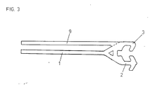
- Figure 3 shows a double-layer seal.
- each lock consists in cross section of a web 1, which is provided with a full arrow head 2 and a half arrow head 3. Between each full arrow head 2 and every half arrow head 3 there is a recess for the insertion of a full arrow head 2 .
- the recess for the full arrow head has a recess 4 in cross section in its foot, into which an injection is made during assembly hose 5 is inserted.
- the injection hose is filled with an injection agent after the complete lowering of a sealing membrane and the intended connection with the previously lowered sealing membrane in both locks, so that the injection hose bulges and then lies against the arrow head 2.
- This causes not only a sealing edge between the injection hose 5 and the arrow head 2, but also a sealing contact of the arrow head 2 with other corresponding sealing surfaces of the recess.
- this is also provided with a bulging sealing lug 6.
- the lock according to the invention also has an injection channel 7, through which further sealant can be pressed into the resulting cavities between arrowhead 2 in the corresponding recess.
- FIG. 2 shows sealant 8 in the pressed-in state. a. a curing synthetic resin.
- the lock is provided with a web 9 in the region of the half arrow head 3.
- the web 9 forms a connection for welding a further sealing membrane.
- the result is a double-layer waterproofing membrane.
- the first layer is created by welding the edge of the waterproofing membrane to the web 1.
- the second layer is created by welding the additional waterproofing membrane to the web 9.
Landscapes
- Engineering & Computer Science (AREA)
- Life Sciences & Earth Sciences (AREA)
- Structural Engineering (AREA)
- Hydrology & Water Resources (AREA)
- General Life Sciences & Earth Sciences (AREA)
- Mining & Mineral Resources (AREA)
- Paleontology (AREA)
- Civil Engineering (AREA)
- General Engineering & Computer Science (AREA)
- Environmental & Geological Engineering (AREA)
- Bulkheads Adapted To Foundation Construction (AREA)
- Revetment (AREA)
- Cartons (AREA)
- Load-Bearing And Curtain Walls (AREA)
Abstract
Description
- Die Erfindung betrifft eine Abdichtung für eine Schlitzwand, wobei ein Erdschlitz eingebracht und mit Bentonit oder dergleichen Stützmasse gefüllt wird und anschließend die Abdichtung in die Stützmasse abgesenkt wird und die Abdichtung aus Bahnen zusammengesetzt wird, die an den Seiten mit ineinander greifenden Schlössern versehen sind, wobei ein Schloß im Querschnitt einePfeilspitze mit Widerhaken bildet, die in entsprechende Ausnehmungen des korrespondierenden Schlosses greift.
- Schlitzwände dienen als Horizontalabdichtung. Mit der Horizontalabdichtung sollen Flüssigkeitsbewegungen im Erdreich verhindert werden. Das hat vor allem für kontaminiertes Erdreich Bedeutung. Bei kontaminiertem Erdreich besteht die Gefahr, daß durch eindringendes Oberflächenwasser und/oder Grundwasserströme Kontaminationsgut in andere Grundwasserbereiche hineingetragen wird. Das läßt sich durch die Vertikalabdichtung vermeiden. Die Vertikalabdichtung durchschneidet den Grundwasserstrom und wird bis in eine flüssigkeitsundurchlässige Erdschicht hineingeführt. D.h. die Vertikalabdichtung wird soweit nach unten gebaut, bis Anschluß an eine flüssigkeitsundurchlässige Erdschicht gefunden ist. Andererseits kann die Vertikalabdichtung auch mit einer Horizontalabdichtung zusammenwirken. Die künstliche Horizontalabdichtung ersetzt dann die natürliche, wasserundurchlässige Erdschicht.
- Ursprünglich wurden derartige Vertikalabdichtungen allein dadurch erzeugt, daß Erdschlitze eingebracht und mit Bentonit verfüllt wurden. Zwischenzeitlich hat sich gezeigt, daß die Dichtwirkung von Bentonit zwar sehr groß aber für die Abdichtung kontaminierter Erdschichten noch nicht ausreichend ist. Deshalb ist zur Abdichtung kontaminierten Erdreiches zusätzlich die Forderung nach einer in den Bentonit absenkbaren Abdichtung gestellt worden. In erster Linie ist dabei an eine Abdichtung gedacht, wie sie bei der Neuanlage von Deponien Anwendung findet. Es handelt sich um Kunststoffbahnen. Das Absenken der Kunststoffbahnen in den Bentonit stellt jedoch erhebliche Probleme Das gilt vor allem für die Nahtstelle zwischen den Abdichtungsbahnen. Während beim Neuanlegen von Deponien die Kunststoffabdichtungsbahnen ausgelegt und miteinander verschweißt werden, ist dies Verfahren bei der zusätzlichen Abdichtung von Erdschlitzen wirtschaftlich nicht anwendbar. Hier ist in der Vergangenheit ein anderer Weg eingeschlagen worden, indem die Absdichtungsbahnen an beiden Seiten mit Schlössern versehen werden, so daß die einzelnen Abdichtungsbahnen - wie dies bei Spundbohlen bekannt - Schloß in Schloß geschoben werden.
- Eine vorteilhafte Schloßform sieht vor, daß im Querschnitt eine Pfeilspitzenform mit Widerhaken gegeben ist, die in entsprechende Ausnehmungen des korrespondierenden Schlosses der benachbarten Bahn eingreift.
- Versuche mit auf dem Markt befindlichen Schlössern zeigen jedoch, daß die Abdichtung nicht zuverlässig wirkt. Im Schloßbereich sind Leckstellen erkennbar geworden.
- Es ist bekannt, diesen Leckstellen mit Hilfe von Schnüren entgegenzuwirken, die in das dazu im Querschnitt mit einer entsprechenden, kleinen Ausnehmung versehene Schloß eingelegt werden und bei der Berührung mit Wasser aufquellen. Auch das deckt noch nicht das Sicherheitsbedürfnis für die Abdichtung kontaminerten Erdreiches.
- Nach einem anderen älteren Vorschlag ist das Schloß im Querschnitt mit mehreren Pfeilspitzen versehen, so daß eine zusätzliche Abdichtung nach Art einer Labyrinthdichtung entsteht.
- Diese vorgeschlagene Abdichtung erfordert aber in der bisherigen Ausführungsform einen erheblichen baulichen Aufwand.
- Der Erfindung liegt die Aufgabe zugrunde, derartige Schlösser mit mehreren im Querschnitt hintereinander liegenden Dichtstellen wirtschaftlich darzustellen.Nach der Erfindung wird das dadurch erreicht, daß jedes Schloß i m Querschnitt zwei Spitzen aufweist, von denen die eine eine volle Pfeilspitze bildet und die andere eine etwa halbe Pfeilspitze bildet.Mit einem solchen Profil entsteht ein Schloß, das für jede Seite einer Abdichtungsbahn verwendet werden kann. Alle Schlösser haben dann gleichen Querschnitt. Das bedeutet eine wesentliche Vereinfachung der Fertigung. Bei der Montage, d. h. beim Verschweißen eines Schlosses mit dem zugehörigen seitlichen Rand einer Abdichtungsbahn ist zu beachten, daß von zwei möglichen Schloßlagen die richtige gewählt wird, damit ein vorgesehenes Ineinanderschieben der Schlösser möglich ist.
- Ein weiterer Vorteil des erfindungsgemäßen Schlosses ist, daß die Profilseite mit der etwa halben Pfeilspitze sich besonders für die Anbringung einer zweiten Abdichtungsbahn zur Erzeugung einer doppellagigen Abdichtung eignet.
- Im übrigen kann das Schloß mit einem Injektionskanal zum Injizieren eines Dichtmittels und/oder einer Ausnehmung zum Einlegen eines Injektionsschlauches versehen sein.
- In der Zeichnung sind zwei Ausführungsbeispiele der Erfindung dargestellt.
- Figur 1 und 2 zeigen eine einlagige Abdichtung, Figur 3 eine doppellagige Abdichtung.
- Nach Figur 1 und 2 besteht jedes Schloß im Querschnitt aus einem Steg 1, der mit einer vollen Pfeilspitze 2 und einer halben Pfeilspitze 3 versehen ist.Zwischen jeder vollen Pfeilspitze 2 und jeder halben Pfeilspitze 3 ist eine Ausnehmung für das Einschieben einer vollen Pfeilspitze 2 vorgesehen.
- Die Ausnehmung für die volle Pfeilspitze weist im Querschnitt in ihrem Fuß eine Vertiefung 4 auf, in die bei der Montage ein Injektions schlauch 5 eingelegt wird. Der Injektionsschlauch wird nach vollständigem Absenken einer Abdichtungsbahn und vorgesehene Verbindung mit der bereits vorher abgesenkten Abdichtungsbahn in beiden Schlössern mit einem Injektionsmittel gefüllt, so daß sich der Injektionsschlauch aufwölbt und sich schließend gegen die Pfeilspitze 2 legt. Das bewirkt nicht nur eine Dichtkante zwischen dem Injektionsschlauch 5 und der Pfeilspitze 2, sondern auch ein dichtendes Anliegen der Pfeilspitze 2 an andere korrespondierende Dichtflächen der Ausnehmung. Zur kontrollierten Ausbildung der Dichtkante zwischen Injektionsschlauch 5 und Pfeilspitze 2 ist diese noch mit einer sich verwölbenden Dichtnase 6 versehen.
- Schließlich besitzt das erfindungsgemäße Schloß noch einen Injektionskanal 7, durch den weiteres Dichtmittel in die entstandenen Hohlräume zwischen der Pfeilspitze 2 in der korrespondierenden Ausnehmung eingepreßt werden kann. Die Figur 2 zeigt Dichtmittel 8 im eingepreßten Zustand.Als Dichtmittel 8 eignet sich u. a. ein aushärtender Kunstharz.
- Nach Figur 3 ist das Schloß im Bereich der halben Pfeilspitze 3 mit einem Steg 9 versehen. Der Steg 9 bildet einen Anschluß für das Verschweißen einer weiteren Abdichtungsbahn. Im Ergebnis entsteht eine doppellagige Abdichtungsbahn. Die erste Lage entsteht durch Verschweißen desseitlichen Randes der Abdichtungsbahn mit dem Steg 1. Die zweite Lage entsteht durch Verschweißen der weiteren Abdichtungsbahn mit dem Steg 9.
Claims (3)
Priority Applications (1)
| Application Number | Priority Date | Filing Date | Title |
|---|---|---|---|
| AT87104869T ATE48864T1 (de) | 1986-10-02 | 1987-04-02 | Doppellagige abdichtung fuer schlitzwand. |
Applications Claiming Priority (2)
| Application Number | Priority Date | Filing Date | Title |
|---|---|---|---|
| DE3633575 | 1986-10-02 | ||
| DE19863633575 DE3633575A1 (de) | 1986-10-02 | 1986-10-02 | Doppellagige abdichtung fuer schlitzwand |
Publications (2)
| Publication Number | Publication Date |
|---|---|
| EP0264527A1 true EP0264527A1 (de) | 1988-04-27 |
| EP0264527B1 EP0264527B1 (de) | 1989-12-20 |
Family
ID=6310912
Family Applications (1)
| Application Number | Title | Priority Date | Filing Date |
|---|---|---|---|
| EP87104869A Expired EP0264527B1 (de) | 1986-10-02 | 1987-04-02 | Doppellagige Abdichtung für Schlitzwand |
Country Status (3)
| Country | Link |
|---|---|
| EP (1) | EP0264527B1 (de) |
| AT (1) | ATE48864T1 (de) |
| DE (2) | DE3633575A1 (de) |
Cited By (9)
| Publication number | Priority date | Publication date | Assignee | Title |
|---|---|---|---|---|
| WO1993009298A1 (en) * | 1991-11-08 | 1993-05-13 | University Of Waterloo | Sealing system for in-ground barrier |
| FR2688245A1 (fr) * | 1992-02-22 | 1993-09-10 | Preussag Stahl Ag | Paroi etanche formee de palplanches et procede pour la realisation de la paroi. |
| WO1994012735A1 (de) * | 1992-11-30 | 1994-06-09 | Progeo Geotechnologiegesellschaft Mbh | Flüssigkeitsdichtes schloss für miteinander verbundene, eine dichtungswand bildende kunstoffbahnen |
| EP0633359A1 (de) * | 1993-07-07 | 1995-01-11 | Arbed S.A. | Wasserdichte Klauenkupplung für Spundbohle |
| EP0628662A3 (de) * | 1993-06-09 | 1995-09-20 | Krupp Hoesch Stahl Ag | Spundwand. |
| EP0684343A1 (de) * | 1994-05-27 | 1995-11-29 | Süd-Chemie Ag | Verfahren zur Herstellung von Dichtwänden |
| EP0684344A1 (de) * | 1994-05-27 | 1995-11-29 | Süd-Chemie Ag | Dichtmittel gegen organische Flüssigkeiten |
| WO1998016691A1 (fr) * | 1996-10-16 | 1998-04-23 | Profilarbed S.A. | Joint d'etancheite pour palplanches |
| CN102535439A (zh) * | 2011-11-24 | 2012-07-04 | 东南大学 | 一种钢板桩锁口结构 |
Families Citing this family (3)
| Publication number | Priority date | Publication date | Assignee | Title |
|---|---|---|---|---|
| DE3733163A1 (de) * | 1987-10-01 | 1989-04-13 | Niederberg Chemie | Abdichtung von schlitzwaenden |
| FI128323B (en) | 2011-11-28 | 2020-03-31 | Rautaruukki Oyj | Spontaneous, pile and pile wall |
| CN109537577A (zh) * | 2017-09-22 | 2019-03-29 | 震东机械设备有限公司 | 用于套管或桩的互锁系统 |
Citations (3)
| Publication number | Priority date | Publication date | Assignee | Title |
|---|---|---|---|---|
| US1341949A (en) * | 1918-05-13 | 1920-06-01 | Troye Einar | Sheet-piling |
| DE2349071A1 (de) * | 1972-09-29 | 1974-04-04 | Leonard L Frederick | Spundwandelement und verfahren zum einbringen desselben |
| EP0129275A1 (de) * | 1983-05-31 | 1984-12-27 | Nico Gerhard Cortlever | Profil zur Herstellung einer wasserdichten Sperrschicht im Boden und Verfahren zum Einbau derselben |
-
1986
- 1986-10-02 DE DE19863633575 patent/DE3633575A1/de not_active Withdrawn
-
1987
- 1987-04-02 AT AT87104869T patent/ATE48864T1/de not_active IP Right Cessation
- 1987-04-02 EP EP87104869A patent/EP0264527B1/de not_active Expired
- 1987-04-02 DE DE8787104869T patent/DE3761212D1/de not_active Expired - Lifetime
Patent Citations (3)
| Publication number | Priority date | Publication date | Assignee | Title |
|---|---|---|---|---|
| US1341949A (en) * | 1918-05-13 | 1920-06-01 | Troye Einar | Sheet-piling |
| DE2349071A1 (de) * | 1972-09-29 | 1974-04-04 | Leonard L Frederick | Spundwandelement und verfahren zum einbringen desselben |
| EP0129275A1 (de) * | 1983-05-31 | 1984-12-27 | Nico Gerhard Cortlever | Profil zur Herstellung einer wasserdichten Sperrschicht im Boden und Verfahren zum Einbau derselben |
Cited By (12)
| Publication number | Priority date | Publication date | Assignee | Title |
|---|---|---|---|---|
| WO1993009298A1 (en) * | 1991-11-08 | 1993-05-13 | University Of Waterloo | Sealing system for in-ground barrier |
| FR2688245A1 (fr) * | 1992-02-22 | 1993-09-10 | Preussag Stahl Ag | Paroi etanche formee de palplanches et procede pour la realisation de la paroi. |
| BE1008197A3 (fr) * | 1992-02-22 | 1996-02-13 | Preussag Stahl Ag | Paroi etanche formee de palplanches et procede pour la realisation de la paroi. |
| WO1994012735A1 (de) * | 1992-11-30 | 1994-06-09 | Progeo Geotechnologiegesellschaft Mbh | Flüssigkeitsdichtes schloss für miteinander verbundene, eine dichtungswand bildende kunstoffbahnen |
| EP0628662A3 (de) * | 1993-06-09 | 1995-09-20 | Krupp Hoesch Stahl Ag | Spundwand. |
| EP0633359A1 (de) * | 1993-07-07 | 1995-01-11 | Arbed S.A. | Wasserdichte Klauenkupplung für Spundbohle |
| US5520487A (en) * | 1993-07-07 | 1996-05-28 | Arbed S.A. | Waterproof clutches for sheet piles |
| EP0684343A1 (de) * | 1994-05-27 | 1995-11-29 | Süd-Chemie Ag | Verfahren zur Herstellung von Dichtwänden |
| EP0684344A1 (de) * | 1994-05-27 | 1995-11-29 | Süd-Chemie Ag | Dichtmittel gegen organische Flüssigkeiten |
| WO1998016691A1 (fr) * | 1996-10-16 | 1998-04-23 | Profilarbed S.A. | Joint d'etancheite pour palplanches |
| US6189890B1 (en) | 1996-10-16 | 2001-02-20 | Profilarbed S.A. | Sealing joint for sheet piles |
| CN102535439A (zh) * | 2011-11-24 | 2012-07-04 | 东南大学 | 一种钢板桩锁口结构 |
Also Published As
| Publication number | Publication date |
|---|---|
| DE3761212D1 (de) | 1990-01-25 |
| EP0264527B1 (de) | 1989-12-20 |
| ATE48864T1 (de) | 1990-01-15 |
| DE3633575A1 (de) | 1988-04-07 |
Similar Documents
| Publication | Publication Date | Title |
|---|---|---|
| EP0264527B1 (de) | Doppellagige Abdichtung für Schlitzwand | |
| DE3416568A1 (de) | Membransperre gegen unterirdische fluidstroemungen und abschnitt dafuer | |
| DE3430789C2 (de) | ||
| DE3419163A1 (de) | Verfahren und vorrichtung zur abdichtung gegen deponie-sickerwasser | |
| EP0690942B2 (de) | Verfahren zur abdichtung von bodenkörpern und vorrichtung zur durchführung dieses verfahrens | |
| DE3632951A1 (de) | Flexible abdichtungsbahn | |
| EP0233989B1 (de) | Widerhaken für Schlossverbindung | |
| EP0684343A1 (de) | Verfahren zur Herstellung von Dichtwänden | |
| EP0286068A1 (de) | Sickersperrwand | |
| EP0227878B1 (de) | Verbindungselemente für Schlitzwände | |
| DE8704794U1 (de) | Absperrschieber für eine Fensteröffnung | |
| DE3914685C2 (de) | Verfahren zum Einziehen einer Dichtsohle für die Untergrundabdichtung eines Geländebereiches | |
| DE19715038B4 (de) | Wasserdurchlässige Filterwand und Verfahren zur Herstellung der Filterwand | |
| EP0233315B1 (de) | Schlitzwand zur Vertikalabdichtung | |
| DE4012301A1 (de) | Schalungshuelle | |
| DE102005062215B3 (de) | Verfahren zum nachträglichen Abdichten einer Fuge zwischen benachbarten Betonblöcken | |
| DE3605252C2 (de) | ||
| EP0294539B1 (de) | Verfahren und Vorrichtung zur Verschweissung von Fugenband | |
| DE3635856A1 (de) | Verbindungsprofil fuer abdichtungsbahnen in schlitzwaenden | |
| DE9102219U1 (de) | Rinnenbauteil für eine extrem dichte Abflußrinne | |
| DE3910788A1 (de) | Kunststoffschloss | |
| DE8620410U1 (de) | Mehrteiliges Verbindungsprofil für eine Schlitzwandabdichtung | |
| DE3709303A1 (de) | Abdichtung fuer schlitzwaende | |
| DE3714743A1 (de) | Deponie mit einer kontrollierbaren deponiesohle | |
| DE8713653U1 (de) | Folienbahn |
Legal Events
| Date | Code | Title | Description |
|---|---|---|---|
| PUAI | Public reference made under article 153(3) epc to a published international application that has entered the european phase |
Free format text: ORIGINAL CODE: 0009012 |
|
| AK | Designated contracting states |
Kind code of ref document: A1 Designated state(s): AT BE CH DE FR LI NL |
|
| 17P | Request for examination filed |
Effective date: 19880317 |
|
| 17Q | First examination report despatched |
Effective date: 19890406 |
|
| GRAA | (expected) grant |
Free format text: ORIGINAL CODE: 0009210 |
|
| AK | Designated contracting states |
Kind code of ref document: B1 Designated state(s): AT BE CH DE FR LI NL |
|
| REF | Corresponds to: |
Ref document number: 48864 Country of ref document: AT Date of ref document: 19900115 Kind code of ref document: T |
|
| ET | Fr: translation filed | ||
| REF | Corresponds to: |
Ref document number: 3761212 Country of ref document: DE Date of ref document: 19900125 |
|
| PLBE | No opposition filed within time limit |
Free format text: ORIGINAL CODE: 0009261 |
|
| STAA | Information on the status of an ep patent application or granted ep patent |
Free format text: STATUS: NO OPPOSITION FILED WITHIN TIME LIMIT |
|
| 26N | No opposition filed | ||
| REG | Reference to a national code |
Ref country code: CH Ref legal event code: PUE Owner name: HT TROPLAST AG |
|
| BECA | Be: change of holder's address |
Free format text: 950306 *HT TROPLAST A.G.:PATENTE/LIZENZEN - GEB. 56 POSTFACH 11 65, D-53839 TROISDORF |
|
| BECH | Be: change of holder |
Free format text: 950306 *HT TROPLAST A.G. |
|
| NLS | Nl: assignments of ep-patents |
Owner name: HT TROPLAST AG;HUELS TROISDORF AKTIENGESELLSCHAFT |
|
| REG | Reference to a national code |
Ref country code: FR Ref legal event code: TP |
|
| REG | Reference to a national code |
Ref country code: CH Ref legal event code: PUE Owner name: HT TROPLAST AG TRANSFER- NEUE FASERTECHNIK GMBH & |
|
| NLS | Nl: assignments of ep-patents |
Owner name: NAUE-FASERTECHNIK GMBH & CO. KG |
|
| REG | Reference to a national code |
Ref country code: FR Ref legal event code: TP |
|
| PGFP | Annual fee paid to national office [announced via postgrant information from national office to epo] |
Ref country code: AT Payment date: 19980312 Year of fee payment: 12 |
|
| PGFP | Annual fee paid to national office [announced via postgrant information from national office to epo] |
Ref country code: BE Payment date: 19980428 Year of fee payment: 12 |
|
| PGFP | Annual fee paid to national office [announced via postgrant information from national office to epo] |
Ref country code: FR Payment date: 19980429 Year of fee payment: 12 |
|
| PGFP | Annual fee paid to national office [announced via postgrant information from national office to epo] |
Ref country code: NL Payment date: 19980430 Year of fee payment: 12 |
|
| PGFP | Annual fee paid to national office [announced via postgrant information from national office to epo] |
Ref country code: CH Payment date: 19980501 Year of fee payment: 12 |
|
| PGFP | Annual fee paid to national office [announced via postgrant information from national office to epo] |
Ref country code: DE Payment date: 19980628 Year of fee payment: 12 |
|
| PG25 | Lapsed in a contracting state [announced via postgrant information from national office to epo] |
Ref country code: AT Free format text: LAPSE BECAUSE OF NON-PAYMENT OF DUE FEES Effective date: 19990402 |
|
| PG25 | Lapsed in a contracting state [announced via postgrant information from national office to epo] |
Ref country code: LI Free format text: LAPSE BECAUSE OF NON-PAYMENT OF DUE FEES Effective date: 19990430 Ref country code: CH Free format text: LAPSE BECAUSE OF NON-PAYMENT OF DUE FEES Effective date: 19990430 Ref country code: BE Free format text: LAPSE BECAUSE OF NON-PAYMENT OF DUE FEES Effective date: 19990430 |
|
| BERE | Be: lapsed |
Owner name: NAUE FASERTECHNIK G.M.B.H. & CO. K.G. Effective date: 19990430 |
|
| PG25 | Lapsed in a contracting state [announced via postgrant information from national office to epo] |
Ref country code: NL Free format text: LAPSE BECAUSE OF NON-PAYMENT OF DUE FEES Effective date: 19991101 |
|
| REG | Reference to a national code |
Ref country code: CH Ref legal event code: PL |
|
| PG25 | Lapsed in a contracting state [announced via postgrant information from national office to epo] |
Ref country code: FR Free format text: LAPSE BECAUSE OF NON-PAYMENT OF DUE FEES Effective date: 19991231 |
|
| NLV4 | Nl: lapsed or anulled due to non-payment of the annual fee |
Effective date: 19991101 |
|
| REG | Reference to a national code |
Ref country code: FR Ref legal event code: ST |
|
| PG25 | Lapsed in a contracting state [announced via postgrant information from national office to epo] |
Ref country code: DE Free format text: LAPSE BECAUSE OF NON-PAYMENT OF DUE FEES Effective date: 20000201 |