EP0264531A1 - Elément filtrant pour un panneau filtrant d'une cabine d'une installation pour laquage au pistolet - Google Patents
Elément filtrant pour un panneau filtrant d'une cabine d'une installation pour laquage au pistolet Download PDFInfo
- Publication number
- EP0264531A1 EP0264531A1 EP87106341A EP87106341A EP0264531A1 EP 0264531 A1 EP0264531 A1 EP 0264531A1 EP 87106341 A EP87106341 A EP 87106341A EP 87106341 A EP87106341 A EP 87106341A EP 0264531 A1 EP0264531 A1 EP 0264531A1
- Authority
- EP
- European Patent Office
- Prior art keywords
- frame
- clamping
- filter element
- filter
- rails
- Prior art date
- Legal status (The legal status is an assumption and is not a legal conclusion. Google has not performed a legal analysis and makes no representation as to the accuracy of the status listed.)
- Granted
Links
Images


Classifications
-
- B—PERFORMING OPERATIONS; TRANSPORTING
- B01—PHYSICAL OR CHEMICAL PROCESSES OR APPARATUS IN GENERAL
- B01D—SEPARATION
- B01D46/00—Filters or filtering processes specially modified for separating dispersed particles from gases or vapours
- B01D46/10—Particle separators, e.g. dust precipitators, using filter plates, sheets or pads having plane surfaces
-
- B—PERFORMING OPERATIONS; TRANSPORTING
- B01—PHYSICAL OR CHEMICAL PROCESSES OR APPARATUS IN GENERAL
- B01D—SEPARATION
- B01D46/00—Filters or filtering processes specially modified for separating dispersed particles from gases or vapours
- B01D46/0002—Casings; Housings; Frame constructions
- B01D46/0005—Mounting of filtering elements within casings, housings or frames
-
- B—PERFORMING OPERATIONS; TRANSPORTING
- B01—PHYSICAL OR CHEMICAL PROCESSES OR APPARATUS IN GENERAL
- B01D—SEPARATION
- B01D46/00—Filters or filtering processes specially modified for separating dispersed particles from gases or vapours
- B01D46/42—Auxiliary equipment or operation thereof
- B01D46/4236—Reducing noise or vibration emissions
-
- B—PERFORMING OPERATIONS; TRANSPORTING
- B01—PHYSICAL OR CHEMICAL PROCESSES OR APPARATUS IN GENERAL
- B01D—SEPARATION
- B01D46/00—Filters or filtering processes specially modified for separating dispersed particles from gases or vapours
- B01D46/56—Filters or filtering processes specially modified for separating dispersed particles from gases or vapours with multiple filtering elements, characterised by their mutual disposition
- B01D46/58—Filters or filtering processes specially modified for separating dispersed particles from gases or vapours with multiple filtering elements, characterised by their mutual disposition connected in parallel
-
- B—PERFORMING OPERATIONS; TRANSPORTING
- B05—SPRAYING OR ATOMISING IN GENERAL; APPLYING FLUENT MATERIALS TO SURFACES, IN GENERAL
- B05B—SPRAYING APPARATUS; ATOMISING APPARATUS; NOZZLES
- B05B16/00—Spray booths
- B05B16/60—Ventilation arrangements specially adapted therefor
-
- B—PERFORMING OPERATIONS; TRANSPORTING
- B05—SPRAYING OR ATOMISING IN GENERAL; APPLYING FLUENT MATERIALS TO SURFACES, IN GENERAL
- B05B—SPRAYING APPARATUS; ATOMISING APPARATUS; NOZZLES
- B05B16/00—Spray booths
- B05B16/90—Spray booths comprising conveying means for moving objects or other work to be sprayed in and out of the booth, e.g. through the booth
- B05B16/95—Spray booths comprising conveying means for moving objects or other work to be sprayed in and out of the booth, e.g. through the booth the objects or other work to be sprayed lying on, or being held above the conveying means, i.e. not hanging from the conveying means
-
- B—PERFORMING OPERATIONS; TRANSPORTING
- B01—PHYSICAL OR CHEMICAL PROCESSES OR APPARATUS IN GENERAL
- B01D—SEPARATION
- B01D2265/00—Casings, housings or mounting for filters specially adapted for separating dispersed particles from gases or vapours
- B01D2265/02—Non-permanent measures for connecting different parts of the filter
- B01D2265/027—Quick closing means for, e.g. filter heads, caps, maintenance openings
-
- B—PERFORMING OPERATIONS; TRANSPORTING
- B05—SPRAYING OR ATOMISING IN GENERAL; APPLYING FLUENT MATERIALS TO SURFACES, IN GENERAL
- B05B—SPRAYING APPARATUS; ATOMISING APPARATUS; NOZZLES
- B05B13/00—Machines or plants for applying liquids or other fluent materials to surfaces of objects or other work by spraying, not covered by groups B05B1/00 - B05B11/00
- B05B13/02—Means for supporting work; Arrangement or mounting of spray heads; Adaptation or arrangement of means for feeding work
- B05B13/04—Means for supporting work; Arrangement or mounting of spray heads; Adaptation or arrangement of means for feeding work the spray heads being moved during spraying operation
- B05B13/0447—Installation or apparatus for applying liquid or other fluent material to conveyed separate articles
- B05B13/0452—Installation or apparatus for applying liquid or other fluent material to conveyed separate articles the objects being vehicle components, e.g. vehicle bodies
-
- B—PERFORMING OPERATIONS; TRANSPORTING
- B05—SPRAYING OR ATOMISING IN GENERAL; APPLYING FLUENT MATERIALS TO SURFACES, IN GENERAL
- B05B—SPRAYING APPARATUS; ATOMISING APPARATUS; NOZZLES
- B05B14/00—Arrangements for collecting, re-using or eliminating excess spraying material
- B05B14/40—Arrangements for collecting, re-using or eliminating excess spraying material for use in spray booths
- B05B14/46—Arrangements for collecting, re-using or eliminating excess spraying material for use in spray booths by washing the air charged with excess material
Definitions
- the invention relates to a filter element for a filter ceiling of a paint spraying booth, which has a rectangular metal profile frame, the frame legs defining a passage opening have approximately horizontal support flanges projecting into the interior of the frame, on which there rests a rectangular grid, which is just like the grid over the passage opening extending filter mat, which is held down by clamp rails attached to the frame legs about horizontal axes and pivoted down onto the filter mat and clamped in the frame.
- the ceiling of the actual cabin space of a paint spraying system cabin is usually designed as a so-called filter ceiling over its entire width. It generally consists of rectangular filter elements, the circumference of which is formed by a frame, and the frames of filter elements which are adjacent to one another are fastened to one another by means of screw connections.
- the length of these rectangular filter elements usually corresponds approximately to the cabin width, which can be, for example, 6 m, while the width of the filter elements extending in the longitudinal direction of the cabin is, for example, 1 m.
- filter elements of the type mentioned at the outset are known, the frames of which are formed by galvanized steel profiles which have an approximately C-shaped cross section, the C opening towards the inside of the frame and one approximately twice compared to its upper leg has up to three times the width of the lower leg, which forms the flange supporting the grille and the filter mat.
- the grid is a galvanized steel wire grid, the edge areas of which are welded onto the mentioned flanges of the frame legs.
- a clamping rail is articulated so that it can be pivoted about a horizontal axis running in the longitudinal direction of the relevant frame leg .
- This clamping rail is also a steel angle rail with an inverted L-shaped cross-section, which forms a U-shaped channel with an inverted cross-section in the pivoted-down state with the supporting angle rail and, due to its own weight, clamps the filter mat between itself and the flange of the frame leg in question.
- a bow-shaped handle is welded onto its side facing the inside of the frame Inside the frame lies next to the clamping rail pivot axis. For this reason, safety bolts must be provided to prevent the clamping rails from falling down unintentionally when changing the filter mat.
- the invention had for its object to provide a light and easy to manufacture filter element in which the filter mat t-supporting grille can be easily attached without this grid assumes the risk of damage to the filter mat.
- this object can be achieved according to the invention in that the frame legs are formed by extruded aluminum profile rails with recesses holding threaded elements and in that clamping elements held down by the threaded elements are provided for clamping the grating between them and the flanges.
- the material for the frame legs will expediently be one of the usual aluminum alloys, but of course other light metal alloys that can be extruded are also suitable.
- the recesses provided in the frame legs can be retracted T-slots into which slot nuts provided with threaded bolts are inserted; these threaded bolts can then protrude through openings in the grille, so that the grille can be attached to the frame legs using washers and nuts. Grooves could also be drawn into the frame legs, into which the edges of the grille are inserted before the grille is fastened, so that they can no longer pose any risk of injury.
- tensioning strips which are held down by the threaded elements and extend along the frame legs, and which cover the edges or the edges of the grid are used as tensioning elements.
- the reduction in production costs also serves if, in particular, self-tapping screws are used as the threaded elements, which is readily possible with an aluminum profile rail, and in a preferred embodiment, longitudinal grooves are drawn into the frame legs as recesses for the threaded elements, into which the screws or the like just let it screw in.
- each frame leg has a drawn-in longitudinal groove, which widens the base of the groove, for holding sliding blocks, on which supports for the hinged aluminum profile rails, which are also articulated to the latter trained clamping rails are attached.
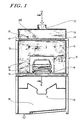
- FIGS. 1 and 2 show a spray booth, designated as a whole as 10, with side walls 12, a grating floor 14, via which vehicle bodies 16 on rail-guided carriages 18 are transported in the longitudinal direction of the paint spraying system, a filter cover 20, which has an inlet air chamber 24 provided with air inlet openings 22 bounded at the bottom, an exhaust air washing device designated as a whole by 26 and an exhaust air chamber 28.
- the work area 30 of the spray booth 10 is evenly supplied with air flowing through the work area from top to bottom via the filter ceiling 20.
- the filter cover 20 is composed of self-supporting filter elements 20A, 20B ... 20G etc. arranged one behind the other in the longitudinal direction of the spray booth, each of which extends over the entire width of the spray booth 10 and is blunt in the longitudinal direction of the spray booth butt together, being screwed together in a manner to be described in more detail.
- FIGS. 1 and 2 The direction of flow of the air through the spray booth 10 was indicated by arrows in FIGS. 1 and 2.
- the spray booth corresponds to the state of the art.
- FIG. 3 of the metal profile frame designated as a whole in FIGS. 1 and 2 will now be explained in more detail.
- this profile rail has a box-shaped hollow profile 42a with an integrally formed lower support flange 42b.
- the latter advantageously has an approximately W-shaped profile with a longitudinal groove 42d drawn into a central web 42c.
- a T-groove 42g is drawn into the aluminum profile rail to form an inner web 42e.
- adjacent filter elements can be fastened to one another via a transverse connecting rail and screws which are screwed into a longitudinal groove which is drawn into the aluminum profile rail and are expediently designed as self-tapping screws.
- a galvanized steel wire grid 50 is placed on the support flanges 42b of the four frame legs 42 of a metal profile frame 40, it being advisable to bend the edge regions 50a of the grid 50 downwards and to insert them into an upwardly open groove 42k, which is formed by the respective support flange 42b. Then four clamping strips 52 are placed on the edges of the grid 50 and fastened with screws 54, which are also self-tapping screws that can be easily screwed into the longitudinal grooves 42d; in this way, the steel wire mesh 50 can be clamped between the four support flanges 42b and the four clamping strips 52. Since, in the embodiment shown in FIG.
- the edge regions 50a of the grating 50 are received in a shielding manner by the grooves 42k of the frame legs 42, it would not be necessary per se to grille to cover the edges with the clamping strips 52, so that it would also be possible in this embodiment to provide only simple washers or the like for the screws 54 instead of the clamping strips 52 in order to securely fasten the grid 50 to the supporting flanges 42b.
- a possibly multi-part filter mat 58 is placed on the grid 50, which according to the invention extends at least almost up to the inner side wall of the hollow profile 42a of all four frame legs 42 and is preferably held on each side of the metal profile frame 40 by a clamping rail 60, which according to the invention is extruded Aluminum profile rail is formed and can be pivoted up from its effective position shown in FIG. 3 in the direction of arrow B around a joint 62 in order to replace the filter mat 58.
- the clamping rail 60 has a cross section in the form of a strongly rounded hook.
- the clamping rail 60 is now designed in such a way that its center of gravity lies between the joint 62 and the hollow profile 42a (seen in the top view) when the clamping rail assumes its ineffective position shown in broken lines in FIG. 3 on the left in FIG. In the pivoted-down state, however, it clamps the filter mat 58 between itself and the relevant clamping bar 52.
- FIG. 4 will now only be described insofar as it differs from the first embodiment shown in FIG. 3, the same reference numerals being used for corresponding parts, but with the addition of a dash in the elements of the embodiment according to FIG. 4th
- the clamping bar 52 ⁇ has the shape of an angle rail, etc. their cross section forms an obtuse angle. It is supported (as in the embodiment according to FIG. 3) with its longitudinal edge facing the hollow profile 42a ⁇ on a sealing cord 70 ⁇ which is inserted into a drawn-in groove of the aluminum profile rail. Since the clamping strip 52 ⁇ also covers an edge region 50a ⁇ of the steel wire mesh 50 ⁇ in this embodiment, the edge region 50a ⁇ was bent upwards in this embodiment.
- threaded bolts 48 ⁇ extending through these frame legs.
- FIG. 5 shows that in the frame legs 42 ⁇ forming aluminum profile rails Longitudinal grooves 42h ⁇ can be drawn in at almost any point where they are useful for attaching the filter elements to other components of the spray booth.
- any holding grooves that serve to hold stiffening strips 80 or 80 ⁇ or 80 ⁇ can be formed - the latter can be Act steel sheet strips that are inserted into the frame legs 42 or 42 ⁇ or 42 ⁇ before joining the frame 40 or 40 ⁇ or 40philgen.
- the steel wire mesh 150 is not only covered and held down by means of a tensioning bar 152, but a tensioning tab 153 fastened to the frame leg 142 with the same screws 154, which are also used to fasten the tensioning bar 152, serves to tension the edges of the mesh to the outside.
- the clamping tab 153 with a hook-shaped bent edge 153a engages behind a wire of the grid 150 that runs perpendicular to the plane of the drawing.
- the profile rails forming the frame legs 142 form, together with the tensioning strips 152, a longitudinal channel 155 into which an elastic seal 157 is inserted, into which the wires of the grid 150, which crosses channel 155, press in. Since the seal 157 is located on the inner edge of the gap formed by the support flange 142b of the frame leg and the clamping bar 152 for receiving the grating 150, the seal can prevent dust which otherwise accumulates in this gap from falling into the interior of the spray booth.
- the pivoted-up clamping rail 160 ends below an upper tread surface 142a, which is formed by the frame legs 142, so that a fitter who has to replace the filter mat 158 can comfortably walk on the frames by means of the tread surfaces 142a.
- the tensioning strip 152 also forms a support angle for the filter mat 158 in this embodiment.
- a particular advantage of the filter elements according to the invention can be seen in the fact that screws are used to fasten the steel wire mesh, but they do not, e.g. also do not protrude into the interior of the spray booth with their screw heads.
Landscapes
- Chemical & Material Sciences (AREA)
- Chemical Kinetics & Catalysis (AREA)
- Filtering Of Dispersed Particles In Gases (AREA)
Applications Claiming Priority (2)
| Application Number | Priority Date | Filing Date | Title |
|---|---|---|---|
| DE3635988 | 1986-10-23 | ||
| DE3635988 | 1986-10-23 |
Related Child Applications (1)
| Application Number | Title | Priority Date | Filing Date |
|---|---|---|---|
| EP90108039.0 Division-Into | 1990-04-27 |
Publications (2)
| Publication Number | Publication Date |
|---|---|
| EP0264531A1 true EP0264531A1 (fr) | 1988-04-27 |
| EP0264531B1 EP0264531B1 (fr) | 1991-01-09 |
Family
ID=6312259
Family Applications (2)
| Application Number | Title | Priority Date | Filing Date |
|---|---|---|---|
| EP87106341A Expired - Lifetime EP0264531B1 (fr) | 1986-10-23 | 1987-05-02 | Elément filtrant pour un panneau filtrant d'une cabine d'une installation pour laquage au pistolet |
| EP90108039A Withdrawn EP0388996A1 (fr) | 1986-10-23 | 1987-05-02 | Elément filtrant pour le panneau filtrant de la cabine d'une installation pour laquage au pistolet |
Family Applications After (1)
| Application Number | Title | Priority Date | Filing Date |
|---|---|---|---|
| EP90108039A Withdrawn EP0388996A1 (fr) | 1986-10-23 | 1987-05-02 | Elément filtrant pour le panneau filtrant de la cabine d'une installation pour laquage au pistolet |
Country Status (3)
| Country | Link |
|---|---|
| EP (2) | EP0264531B1 (fr) |
| DE (1) | DE3767268D1 (fr) |
| ES (1) | ES2020221B3 (fr) |
Cited By (3)
| Publication number | Priority date | Publication date | Assignee | Title |
|---|---|---|---|---|
| EP2218490A1 (fr) * | 2009-01-30 | 2010-08-18 | General Electric Company | Système de rétention de filtre |
| CN110420789A (zh) * | 2019-07-31 | 2019-11-08 | 江西昌河汽车有限责任公司 | 一种节能环保的汽车生产涂装车间 |
| SE2251312A1 (en) * | 2022-11-10 | 2024-05-11 | Husqvarna Ab | An air cleaner with improved filter holding means |
Families Citing this family (2)
| Publication number | Priority date | Publication date | Assignee | Title |
|---|---|---|---|---|
| US5512017A (en) * | 1994-11-23 | 1996-04-30 | Durr Industries, Inc. | Paint spray booth and supply plenum arrangement |
| CN108800322A (zh) * | 2018-06-21 | 2018-11-13 | 郑州源冉生物技术有限公司 | 一种生物技术空气净化装置 |
Citations (5)
| Publication number | Priority date | Publication date | Assignee | Title |
|---|---|---|---|---|
| US2685923A (en) * | 1953-04-27 | 1954-08-10 | Charles H Laws | Filter panel mounting means |
| DE1607667A1 (de) * | 1967-01-13 | 1969-10-02 | American Air Filter Co | Gasfilter-Haltevorrichtung |
| DE1507826A1 (de) * | 1965-03-31 | 1970-01-02 | Modiano Geb Najar | Filterplatte |
| GB1331274A (en) * | 1969-10-23 | 1973-09-26 | American Air Filter Co | Filter cell sealing and retaining arrangement |
| DE2449065A1 (de) * | 1974-10-15 | 1976-04-29 | Luft Und Trockentechnik Kg Sch | Filterdecke fuer lackier- und trockenkabinen o.dgl. |
-
1987
- 1987-05-02 EP EP87106341A patent/EP0264531B1/fr not_active Expired - Lifetime
- 1987-05-02 DE DE8787106341T patent/DE3767268D1/de not_active Revoked
- 1987-05-02 EP EP90108039A patent/EP0388996A1/fr not_active Withdrawn
- 1987-05-02 ES ES87106341T patent/ES2020221B3/es not_active Expired - Lifetime
Patent Citations (5)
| Publication number | Priority date | Publication date | Assignee | Title |
|---|---|---|---|---|
| US2685923A (en) * | 1953-04-27 | 1954-08-10 | Charles H Laws | Filter panel mounting means |
| DE1507826A1 (de) * | 1965-03-31 | 1970-01-02 | Modiano Geb Najar | Filterplatte |
| DE1607667A1 (de) * | 1967-01-13 | 1969-10-02 | American Air Filter Co | Gasfilter-Haltevorrichtung |
| GB1331274A (en) * | 1969-10-23 | 1973-09-26 | American Air Filter Co | Filter cell sealing and retaining arrangement |
| DE2449065A1 (de) * | 1974-10-15 | 1976-04-29 | Luft Und Trockentechnik Kg Sch | Filterdecke fuer lackier- und trockenkabinen o.dgl. |
Cited By (5)
| Publication number | Priority date | Publication date | Assignee | Title |
|---|---|---|---|---|
| EP2218490A1 (fr) * | 2009-01-30 | 2010-08-18 | General Electric Company | Système de rétention de filtre |
| CN101818689B (zh) * | 2009-01-30 | 2013-03-27 | 通用电气公司 | 过滤器固持系统 |
| CN110420789A (zh) * | 2019-07-31 | 2019-11-08 | 江西昌河汽车有限责任公司 | 一种节能环保的汽车生产涂装车间 |
| SE2251312A1 (en) * | 2022-11-10 | 2024-05-11 | Husqvarna Ab | An air cleaner with improved filter holding means |
| SE546926C2 (en) * | 2022-11-10 | 2025-03-11 | Husqvarna Ab | An air cleaner with improved filter holding means |
Also Published As
| Publication number | Publication date |
|---|---|
| EP0388996A1 (fr) | 1990-09-26 |
| ES2020221B3 (es) | 1991-08-01 |
| EP0264531B1 (fr) | 1991-01-09 |
| DE3767268D1 (de) | 1991-02-14 |
Similar Documents
| Publication | Publication Date | Title |
|---|---|---|
| EP0332672B1 (fr) | Revetement de plafond | |
| DE3802309C2 (fr) | ||
| EP0465427A1 (fr) | Superstructure de caisse pour véhicules ferroviaires | |
| DE3921064C2 (fr) | ||
| EP0264531B1 (fr) | Elément filtrant pour un panneau filtrant d'une cabine d'une installation pour laquage au pistolet | |
| CH663067A5 (de) | Wagenkastenaufbau, insbesondere fuer strassen- oder schienenfahrzeuge. | |
| EP0298328B1 (fr) | Mur de façade | |
| DE19858186A1 (de) | Schalung zum Betonieren von auskragenden Betonbauteilen, insbesondere Kappen, Gesimsen und Überbauten | |
| DE4231264A1 (de) | Reinigungsvorrichtung für Reinraumbereiche | |
| DE3330132A1 (de) | Rahmen | |
| DE102006052854B4 (de) | Großraumkabine zur Behandlung von Werkstücken | |
| DE9110828U1 (de) | Gerüst | |
| DE68903348T2 (de) | Aufbauten vom typ sattelauflieger mit plane. | |
| DE8706335U1 (de) | Filterelement für eine Filterdecke einer Lackspritzanlagenkabine | |
| DE1938643A1 (de) | Unterdecke | |
| EP0268197B1 (fr) | Echafaudage, plus spécialement échafaudage pour le bâtiment | |
| DE4004036A1 (de) | Aufhaengevorrichtung fuer tragrohre von kraftfahrzeug-ladebordwaenden | |
| EP0168348B1 (fr) | Fixation de carrosserie sur un châssis | |
| DE8717821U1 (de) | Filterelement für eine Filterdecke einer Lackspritzanlagenkabine | |
| DE4308982A1 (de) | Förderband | |
| DE3623630A1 (de) | Kabinenkonstruktion | |
| DE3249938C2 (fr) | ||
| DE102007031032B3 (de) | Modular aufgebaute, zerlegbare Trennwand | |
| DE4311788A1 (de) | Lauf- und Arbeitsflächen-Element | |
| DE4342106A1 (de) | Tragprofilschiene |
Legal Events
| Date | Code | Title | Description |
|---|---|---|---|
| PUAI | Public reference made under article 153(3) epc to a published international application that has entered the european phase |
Free format text: ORIGINAL CODE: 0009012 |
|
| AK | Designated contracting states |
Kind code of ref document: A1 Designated state(s): DE ES IT |
|
| 17P | Request for examination filed |
Effective date: 19880330 |
|
| 17Q | First examination report despatched |
Effective date: 19890712 |
|
| GRAA | (expected) grant |
Free format text: ORIGINAL CODE: 0009210 |
|
| AK | Designated contracting states |
Kind code of ref document: B1 Designated state(s): DE ES IT |
|
| XX | Miscellaneous (additional remarks) |
Free format text: TEILANMELDUNG 90108039.0 EINGEREICHT AM 02/05/87. |
|
| REF | Corresponds to: |
Ref document number: 3767268 Country of ref document: DE Date of ref document: 19910214 |
|
| ITF | It: translation for a ep patent filed | ||
| PLBI | Opposition filed |
Free format text: ORIGINAL CODE: 0009260 |
|
| 26 | Opposition filed |
Opponent name: ABB FLAEKT AKTIEBOLAG Effective date: 19911009 |
|
| PGFP | Annual fee paid to national office [announced via postgrant information from national office to epo] |
Ref country code: DE Payment date: 19920411 Year of fee payment: 6 |
|
| PGFP | Annual fee paid to national office [announced via postgrant information from national office to epo] |
Ref country code: ES Payment date: 19920507 Year of fee payment: 6 |
|
| RDAG | Patent revoked |
Free format text: ORIGINAL CODE: 0009271 |
|
| STAA | Information on the status of an ep patent application or granted ep patent |
Free format text: STATUS: PATENT REVOKED |
|
| 27W | Patent revoked |
Effective date: 19921107 |