EP0264533B1 - Amortisseur pour mécanismes de marteaux d'impression - Google Patents
Amortisseur pour mécanismes de marteaux d'impression Download PDFInfo
- Publication number
- EP0264533B1 EP0264533B1 EP87106469A EP87106469A EP0264533B1 EP 0264533 B1 EP0264533 B1 EP 0264533B1 EP 87106469 A EP87106469 A EP 87106469A EP 87106469 A EP87106469 A EP 87106469A EP 0264533 B1 EP0264533 B1 EP 0264533B1
- Authority
- EP
- European Patent Office
- Prior art keywords
- damping
- armature
- lever
- damping element
- rebound
- Prior art date
- Legal status (The legal status is an assumption and is not a legal conclusion. Google has not performed a legal analysis and makes no representation as to the accuracy of the status listed.)
- Expired - Lifetime
Links
- 238000013016 damping Methods 0.000 title claims description 62
- 230000007246 mechanism Effects 0.000 title claims description 29
- 230000033001 locomotion Effects 0.000 claims description 17
- 230000006835 compression Effects 0.000 claims description 12
- 238000007906 compression Methods 0.000 claims description 12
- 238000007639 printing Methods 0.000 claims description 12
- 239000011358 absorbing material Substances 0.000 claims description 11
- 230000008878 coupling Effects 0.000 claims description 7
- 238000010168 coupling process Methods 0.000 claims description 7
- 238000005859 coupling reaction Methods 0.000 claims description 7
- 230000000694 effects Effects 0.000 claims description 7
- 230000002457 bidirectional effect Effects 0.000 claims description 3
- 230000010355 oscillation Effects 0.000 claims description 3
- 239000003190 viscoelastic substance Substances 0.000 claims 1
- 230000004048 modification Effects 0.000 description 8
- 238000012986 modification Methods 0.000 description 8
- 229920001971 elastomer Polymers 0.000 description 6
- 239000000806 elastomer Substances 0.000 description 6
- 239000013536 elastomeric material Substances 0.000 description 6
- 239000010408 film Substances 0.000 description 6
- 238000000034 method Methods 0.000 description 5
- 230000001133 acceleration Effects 0.000 description 4
- 238000004804 winding Methods 0.000 description 4
- 230000003213 activating effect Effects 0.000 description 3
- 230000004044 response Effects 0.000 description 3
- 230000002441 reversible effect Effects 0.000 description 3
- 230000008901 benefit Effects 0.000 description 2
- 229920005549 butyl rubber Polymers 0.000 description 2
- 239000004020 conductor Substances 0.000 description 2
- 230000003116 impacting effect Effects 0.000 description 2
- 239000000463 material Substances 0.000 description 2
- 230000021715 photosynthesis, light harvesting Effects 0.000 description 2
- 229920002635 polyurethane Polymers 0.000 description 2
- 239000004814 polyurethane Substances 0.000 description 2
- 230000035939 shock Effects 0.000 description 2
- 238000010521 absorption reaction Methods 0.000 description 1
- 230000009471 action Effects 0.000 description 1
- 239000012190 activator Substances 0.000 description 1
- 230000002730 additional effect Effects 0.000 description 1
- 238000004026 adhesive bonding Methods 0.000 description 1
- 230000002411 adverse Effects 0.000 description 1
- 238000010009 beating Methods 0.000 description 1
- 238000006243 chemical reaction Methods 0.000 description 1
- 230000003247 decreasing effect Effects 0.000 description 1
- 230000003111 delayed effect Effects 0.000 description 1
- 230000009977 dual effect Effects 0.000 description 1
- 230000000977 initiatory effect Effects 0.000 description 1
- 230000000670 limiting effect Effects 0.000 description 1
- 230000005389 magnetism Effects 0.000 description 1
- 238000004519 manufacturing process Methods 0.000 description 1
- 230000036961 partial effect Effects 0.000 description 1
- 230000002093 peripheral effect Effects 0.000 description 1
- 230000008569 process Effects 0.000 description 1
- 230000002829 reductive effect Effects 0.000 description 1
- 230000000717 retained effect Effects 0.000 description 1
- 239000010409 thin film Substances 0.000 description 1
- 238000004073 vulcanization Methods 0.000 description 1
Images

Classifications
-
- B—PERFORMING OPERATIONS; TRANSPORTING
- B41—PRINTING; LINING MACHINES; TYPEWRITERS; STAMPS
- B41J—TYPEWRITERS; SELECTIVE PRINTING MECHANISMS, i.e. MECHANISMS PRINTING OTHERWISE THAN FROM A FORME; CORRECTION OF TYPOGRAPHICAL ERRORS
- B41J9/00—Hammer-impression mechanisms
- B41J9/42—Hammer-impression mechanisms with anti-rebound arrangements
Definitions
- This invention relates to print hammer mechanisms and particularly to damping apparatus for quickly settling print hammer mechanisms.
- the repetition rate of the print hammer mechanism is limited by the time it takes the hammer mechanism to come to rest, i.e. to settle at its initial or rest position, after printing impact occurs.
- a print hammer or other impact element is propelled in free flight at high velocity to effect printing on a print medium which may consist of ink ribbon and paper.
- the resulting impact causes the hammer to rebound with a substantial portion of the original kinetic energy which must be dissipated to bring the hammer to rest.
- Both registration and print density are adversely affected if the actuated elements of the hammer mechanism are not settled and restored to their rest position before the next printing operation occurs.
- a subsequent hammer mechanism operation prior to settling varies both the magnitude and timing of the transmitted impact force so that variable density and misregistration result in the print.
- a different method has been to trap or block the rebounding hammer as it returns from impact with the type, such as shown in U.S. Patents 3, 142,064; 2,696,782 and 2,353,057.
- a print hammer car ries a freely movable weight which is impelled against the hammer as a result of the hammer impacting the type and again when the hammer is arrested at its home position. While this arrangement prevents the hammer from making a second impression, it does not prevent the hammer from rebounding off the backstop and does not appreciably reduce settle time. Furthermore, greater energy must be expended to operate the hammer as a consequence of the added weight carried by the hammer. Examples of this arrangement are shown in U.S. Patents 2,616,366, US-A-3 919 936 and 2,625,100.
- an apparatus of the type comprising a damping element located in the path of travel of said actuated element so as to be impacted by said actuated element upon rebound thereof and mounted for bidirectional movement along said path, said apparatus further comprising: means for urging continuously said damping element in a first direction corresponding to the print direction of said actuated element, said damping element forcibly engaging said actuated element when same is at rest and moving in said first direction at a slower rate than said actuated element upon actuation of the latter for printing; stop means for stopping the movement of said damping element in a second direction opposite to said first direction and allowing its rebound in said first direction, said damping element engaging said actuated element and said stop means in alternate energy transfer collisions during rebound of said actuated element in said second direction; said damping element and said actuated element having a mass ratio whereby said damping element will rebound as a result of a collision with said actuated
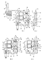
- FIG. 1 shows a three piece print hammer mechanism of the inertial type and comprises hammer element 19, push element 18 and an electromagnetic actuator.
- the actuator comprises magnetic armature 10, magnetic core 14 having poles 12, 13 and energizing windings 15, 16.
- Drive pulses for energizing windings 15, 16 for operating the hammer mechanism are supplied by circuitry of any well known type, not shown, through an electrical connector to conductors 17.
- Hammer element 19 rotates on pin 20 supported by machine frame 22.
- An impact surface 21 of hardened material near the end of the upper arm of hammer element 19 is aligned with a type carrier for printing.
- a return spring 25 has a plunger 23, both within a recess in frame 22, bearing on the lower arm surface 24 of hammer element 19 below pivot 20. Return spring 25 is maintained under partial compression to apply a bias force continuously urging hammer 19 to rotate clockwise around pivot 20 to the rest position.
- Push element 18 is slidable within a guide, not shown, and has opposite ends in abutting engagement with the upper end of armature 10 and hammer element 19 above pivot 20.
- Armature 10 is rotatable on pivot pin 11 supported by side plates 29, 30 attached to core 14 by screws 29, 31. Pins 32 through side plates 29, 30 and core 14 are provided to maintain operational alignment.
- the hammer element 19 and armature 10 are in the rest or restored position.
- the rest position is established by a backstop assembly which, according to this invention, is also a damping means for the hammer mechanism.
- the backstop assembly takes the form of lever 34 pivotally mounted by pivot pin 37 between mounting plates 29, 30.
- a bumper screw 33 extends from upper arm of lever 34 and has a pad 35 of energy absorbing material for contacting armature 10.
- a suitable material for pad 35 is an elastomer such as polyurethane.
- a threaded connection with lever 34 enables the extension of bumper screw 33 to be varied for adjusting the rest position of armature 10 and hammer element 19.
- Lock nut 36 holds the bumper screw 33 against rotation caused by vibration.
- Lever 34 has a tail portion 40 that aligns with a stop surface 42 formed in core 14 between plates 29, 30.
- a thin film 41 of polyurethane or other energy absorbing material is carried by tail portion 40 for engagement with surface 42.
- film 41 may be affixed to stop surface 42.
- Partially compressed spring 39 and plunger 38, both within a recess in the lower arm of lever 34 apply a bias force continuously urging armature 10 to rotate clockwise on pivot pin 11 and lever 34 to rotate counterclockwise on pivot pin 37.
- Spring 39 has a relatively low spring force compared to spring 25 whereby spring 25 operating on hammer 19, push rod 18, armature 10, and lever 34 overcomes the bias force of spring 39 and maintains armature 10 in engagement with pad 35 on bumper screw 33 and retains tail portion 40 of lever 34 in engagement with stop shoulder 42 when the system is settled and in the rest position.
- armature 10 is suddenly attracted to poles 12 and 13 by energizing coils 15 and 16 with drive pulses applied to through conductors 17. Armature 10 thereby rotates counterclockwise on pivot 11.
- coils 14 and 15 are energized with high amplitude short duration current pulses at a rate which increases the rate of armature acceleration until such time as it is arrested abruptly by impacting the poles 12, 13 of core 14.
- push element 18 is being displaced to the left.
- Hammer element 19 at the same time is being rotated in the counterclockwise direction around its pivot 20 against the bias force of spring 25 causing spring 25 to be further compressed by force applied by surface 24 against plunger 23.
- armature 10 is arrested by poles 12 and 13, armature 10, push element 18 and hammer 19 were traveling together.
- the momentum of push element 18 and hammer 19 at the moment armature 10 is arrested is sufficient to continue movement to a point of impact with type to effect printing.
- the push element 18 may continue movement in contact with the hammer to the point of impact or may become separated as a result of friction with the guide or by some structure limiting its leftward translation. In either case the energy level of hammer 19 is sufficient to cause it to rebound on impact at a very high speed toward the arrested armature.
- the current drive pulses will have ended and coils 15, 16 will have been de-energized before the rebounding hammer 19 brings push element 18 into reengagement with armature 10.
- armature 10 will be held in its arrested position by residual magnetism in core 14. As a result, the impact of push element 18 on armature 10 during rebound of hammer 19 causes armature 10 to break away with some slight dissipation of rebound kinetic energy in hammer 19.
- lever 34 Because of the relatively low velocity induced in lever 34 by spring 39, lever 34 will have moved only a small portion of its permissible unrestricted travel toward the activated armature 10 when print hammer 19 and push element 18 rebound and reengage armature 10. This starts armature 10 rotating clockwise as a result of the rebound kinetic energy transferred to it by the rebounding hammer 19. The clockwise rotation of armature 10 reduces the compression on spring 39 thereby reducing the acceleration which caused the counterclockwise rotation of lever 34. The counter motions of armature 10 and lever 34 produce a collision whereby most of the kinetic energy present in armature 10 is transferred to lever 34. This action results in the slowing or stopping of armature 10 before it reaches its rest position.
- lever 34 may rebound from the collision of tail portion 40 with stop shoulder 42 thereby recolliding with armature 10 at greatly reduced energy level causing additional energy dissipation of rebound energy in armature 10 and allowing the bias force of spring 25 on hammer 19 to dominate and force armature 10 and lever 34 to settle at their respective rest positions in readiness for the next operation.
- the alternate collisions and rebounding of lever 34 between armature 10 and stop shoulder 42 in combination with the non-reversable rotation of armature 10 produces rapid removal of hammer rebound energy and achieves rapid hammer settling.
- Lever 34 can have an effective mass either less or greater than armature 10 but maximum slowing or actual stopping of the armature on the initial collision is obtained when the ratio of the effective masses of lever 34 to armature 10 is equal to or slightly less than unity. In the preferred embodiment, the ratio of the effective masses is between 1.0 and 0.5. In addition to insuring rapid settling, via efficient transfer of energy from armature 10 to lever 34, there is an assurance with the range of mass ratios specified, that settling is not delayed by causing armature 10 to reverse direction during rebound.
- pad 35 and film 41 While elastomer pad 35 and film 41 along with spring 39 absorb some energy from the system, pad 35 and film 41 can be relatively thin so that the amount of energy absorbed by them can be relatively small and within their ability to absorb the shock of the collisions without becoming distorted. This is an advantage over known arrangements where thicker pads of compressible energy absorbing materials located at fixed stop positions are used.
- FIG. 3 A modification of an electromagnetic actuator showing a second embodiment of the invention is described in FIG. 3.
- like reference numbers are used to identify identical elements of FIGS. 1 and 2.
- the damping means is a movable backstop assembly that uses two relatively movable damping masses, designated primary and secondary masses, coupled in a damping arrangement by energy absorbing material.
- the primary damping mass is a lever 50 that rotates about pivot pin 37 and has a tail portion 51 engaging a thin elastomer pad 52 between it and a stop surface on the edge of core 14.
- a plunger 53 extends from drilled opening 54 under the influence of compression spring 55 and engages armature 10 so that the lever 50 and armature 10 are urged in opposite rotational directions about their respective pivots.
- Lever 50 also carries adjustable bumper 56 having elastomer pad 57 and lock nut 58 as in the embodiment of FIG. 1.
- Lock nut 58 is located within a cut out 59 in lever 50.
- the spring force of spring 55 is relatively low so that it is readily overcome by the bias force of spring 25 on hammer 19 whereby armature 10 is restored and maintained in contact with pad 57 and tail portion 51 is in contact with film 52 when settled at the rest position.
- a secondary damping mass 60 is supported on lever 50 and is resiliently coupled thereto by pads 61 and 62 of energy absorbing material. Pads 61 and 62 are preferably an elastomer such as butyl rubber and attachment to lever 50 and mass is by adhesive bonding or vulcanization.
- the effective mass of the backstop assembly may be greater or less than the effective mass of armature 10 but preferably the ratio is unity or less. This assures that the backstop assembly will rebound upon collision with armature 10 without causing armature 10 to rebound in the counterclockwise direction.
- the ratio of the secondary damping mass 60 and the effective mass of lever 50 is preferably equal to unity. However, this ratio is not critical and can vary so long as the effective mass of the total backstop assembly is equal to or less than unity so that armature 10 does not rebound upon collision with the backstop assembly.
- armature 10 accelerates rapidly in the counterclockwise direction when activated.
- Lever 50 is thereby freed to rotate in response to the bias force exerted on lever 50 by the compressed spring 55.
- Rotation of lever 50 is in the same direction as but at a slower rate than armature 10.
- armature 10 becomes disengaged from pad 57 of bumper 56 and tail portion 51 becomes disengaged from film 52 on the stop surface of core 14 and the backstop assembly will have moved a small portion of its permissible unrestricted travel in position for a collision engagement with armature 10.
- clockwise rotating armature 10 causes the compression of spring 55 thereby reducing the counterclockwise acceleration of lever 50 and its supported elements.
- clockwise rotating armature 10 collides with pad 57 of the slow moving or stopped backstop assembly when tail portion 51 is at a short distance from the stop surface of core 14 causing the backstop assembly to rebound and move in the clockwise direction.
- the collision and rebounding of the backstop assembly severely slows or, depending on the ratio of the effective masses, temporarily stops armature 10 without causing it to rebound in the counterclockwise direction.
- the collision causes a reactive damping to occur in the backstop assembly.
- This reactive damping occurs as a result of the out of phase motion of mass 60 relative to lever 50 and the damping produced by the shear and compression of pads 61 and 62.
- the relative motion of the damping masses occurs when armature 10 collides with lever 50. This causes lever 50 to be arrested and reverse its rotation. The reverse rotation of lever 50 is temporarily opposed by the inertia or momentum of damping mass 60 supported by pads 61 and 62. Because of this relative motion, pad 61 is subjected to shear stresses and pad 62 is subjected to compression stresses which serve to absorb substantial addition energy transferred to the backstop assembly by armature 10.
- FIG. 4 Another modification of the actuator damping mechanism is shown in FIG. 4 in which the reactive mass damping is performed by a pivoted lever to produce multiple impacts on the rebounding armature.
- the reactive mass is an assembly of lever 65 carrying a pair of bumpers 66, 67 with lever 65 being pivotally mounted on pin 68 supported on fixed extension 69 on side plates 29 and 30.
- Spring 70 retained in suitable recesses in the lower portions of lever 65 and armature 10 and maintained under compression by the larger force of the return spring 25 (FIG. 1) urges actuator 10 and lever 65 to rotate in opposite directions about respective pivots 11 and 68.
- Bumpers 66 and 67 each having a thin layer of energy absorbing elastomeric material 71, are threadedly mounted in lever 65 and secured with a lock nut 72.
- the effective mass of lever 65 with bumpers 66 and 67 is preferably approximately the same as the effective mass of armature 10 and causes armature 10 to severely slow or momentarily stop during its return to the restored rest position.
- FIGS. 5 and 6 Modification of the reactive mass lever 65 are shown in FIGS. 5 and 6.
- a magnet 74 is attached to lever 65 and establishes an armature return force and rotation biasing forces for lever 65.
- the rotational biasing by magnet 74 assures that both bumpers 66 and 67 will not be struck simultaneously by the rebounding armature 10.
- elastomeric inserts 75 have been added in which bumpers 66 and 67 have been mounted. The inserts act in shear and provide added damping between lever 65 and the bumpers.
- reactive mass lever 76 is pivoted on pin 77 supported in side plates 29, 30.
- the lever carries bumper 78 with pad 79 of thin elastomeric material and over lock nut 80.
- Magnetic core 14 has an extension 81 thereon carrying a thin pad 82 of elastomeric material and a light compression spring 83 between extension 81 and lever 76 urging lever 76 to rotate counterclockwise about its pivot 77.
- Hammer return spring 25 maintains both armature 10 and lever 76 at their clockwise limit when in the settled state. When the armature 10 is rapidly attracted counterclockwise, lever 76 moves in the same direction at a slower rate.
- FIGS. 8 and 9 illustrate a further modification of a reactive mass damping system for a print hammer actuator.
- the armature 10 pivots about shaft 11 and is urged to the right by a print hammer spring and push element as in FIG. 1.
- armature 10 engages pad 85 of elastomeric material carried on a thimble-shaped hub 86 having supported thereon a rim 87 by radial spokes 88 of elastomeric material.
- a post 89 On the inner surface of the hub 86 is slidingly supported a post 89 having a pad 90 of elastomeric material for engaging the inner end surface of the hub.
- the post 89 is adjustably threaded into an extension 91 of magnetic core 14, and a light spring 92 on post 89 urges hub 86 toward armature 10 away from magnetic core extension 91.
- hammer spring 25 (FIG. 1) is able to overcome spring 92 and urge armature 10 and hub 86 to their right hand limit.
- armature 10 is attracted suddenly against poles 12 and 13 to drive push rod and hammer to the printing position. This allows spring 92 to slide hub 86 with attached rim 81 and spokes 88 toward the left at a slow rate.
- armature 10 engages pad 85 and hub 86 with attached rim 87 in a "free space” so that rebound energy is absorbed and transferred rapidly thus slowing armature and hammer.
- the original direction of the hub and rim assembly is reversed and it then engages pad 90 on post 89 compressing spring 92.
- the print actuator assembly can accommodate a range of activating energies applied to the activator or armature.
Landscapes
- Impact Printers (AREA)
Claims (10)
- Amortisseur du mouvement par rebond d'un élément actionné (10) d'un mécanisme de marteaux d'impression utilisé pour imprimer des données sur un support d'impression, ledit mécanisme de marteaux d'impression comprenant un positionneur électro-magnétique, ledit amortisseur étant du type comprenant un élément d'amortissement (34, 50-60, 65, 76, 86) placé dans le trajet du parcours dudit élément actionné (10) de manière à être frappé par ledit élément actionné (10) lors de son rebond, et
ledit amortisseur comprenant en outre:- des moyens (39, 55, 70, 83, 92) pour pousser continûment ledit élément d'amortissement (34, 50-60, 65, 76, 86) dans une première direction correspondant à la direction d'impression dudit élément actionné (10), ledit élément d'amortissement (34, 50-60, 65, 76, 86) venant s'engager par force avec ledit élément actionné (10) lorsque ce dernier est au repos et se déplaçant dans ladite première direction à une cadence plus faible que ledit élément actionné (10) lors de la mise en action de ce dernier pour une impression;- des moyens d'arrêt (40, 51, 67, 82, 90) pour arrêter le mouvement dudit élément d'amortissement (34, 50-60, 65, 76, 86) dans une deuxième direction opposée à ladite première direction et permettant son rebond dans ladite première direction, ledit élément d'amortissement (34, 50-60, 65, 76, 86) venant s'engager avec ledit élément actionné (10) et lesdits moyens d'arrêt (40, 51, 67, 82, 90) en collisions de transfert d'énergie alternées durant le rebond dudit élément actionné (10) dans ladite deuxième direction;
ledit élément d'amortissement (34, 50-60, 65, 76, 86) et ledit élément actionné (10) ayant un rapport de masses qui fait que ledit élément d'amortissement (34, 50-60, 65, 76, 86) va rebondir à la suite d'une collision avec ledit élément actionné (10) sans inverser la direction de rebond dudit élément actionné (10); et- des moyens d'absorption d'énergie (41, 52, 71, 82, 90) pour amortir les oscillations dudit élément d'amortissement (34, 50-60, 65, 76, 86) résultant desdites collisions alternées. - Amortisseur selon la revendication 1, dans lequel lesdits moyens d'arrêt comprennent une surface d'arrêt (40, 51) sur ledit élément d'amortissement, ladite surface d'arrêt venant s'engager avec une surface d'arrêt (42, 82, 90) formée sur ledit positionneur électro-magnétique, lorsque ledit élément d'amortissement (34, 50-60, 76, 86) se déplace dans ladite deuxième direction.
- Amortisseur selon la revendication 1, dans lequel lesdits moyens d'arrêt comprennent un élément butoir (71) venant s'engager avec ledit élément actionné (10) lorsque ledit élément d'amortissement (65) se déplace dans ladite deuxième direction.
- Amortisseur selon l'une quelconque des revendications précédentes, dans lequel ledit rapport de masses est sensiblement égal ou inférieur à l'unité.
- Amortisseur selon la revendication 4, dans lequel ledit rapport de masses est compris entre 0,5 et 1,0.
- Amortisseur selon les revendications 1, 2, 4 ou 5, dans lequel ledit élément d'amortissement comprend deux masses d'amortissement (50, 60) en mouvement relatif entre elles pour effectuer l'amortissement dudit élément d'amortissement à la suite desdites collisions alternées.
- Amortisseur selon la revendication 6, dans lequel ledit élément d'amortissement comprend en outre un matériau d'absorption d'énergie (61, 62) couplant lesdites masses d'amortissement en mouvement relatif (50, 60) et agissant avec celles-ci pour effectuer l'amortissement desdites oscillations dudit élément d'amortissement.
- Amortisseurs selon la revendication 7, dans lequel ledit matériau d'absorption d'énergie est un matériau visco-élastique.
- Amortisseur selon les revendications 7 ou 8, dans lequel ledit matériau d'absorption d'énergie a des première (61) et deuxième (62) portions de couplage, ladite première portion de couplage (61) formant un couplage à cisaillement et ladite deuxième portion de couplage formant un couplage à compression/tension, respectivement entre lesdites deux masses d'amortissement (50, 60).
- Amortisseur selon l'une quelconque des revendications précédentes, dans lequel ledit élément d'amortissement est un levier (34, 50, 65, 76) monté sur pivot pour ledit mouvement bidirectionnel afin d'effectuer sur des portions différentes lesdites collisions alternées avec ledit élément actionné (10).
Applications Claiming Priority (2)
| Application Number | Priority Date | Filing Date | Title |
|---|---|---|---|
| US920639 | 1986-10-20 | ||
| US06/920,639 US4722622A (en) | 1986-10-20 | 1986-10-20 | Damping apparatus for a print hammer mechanism |
Publications (3)
| Publication Number | Publication Date |
|---|---|
| EP0264533A2 EP0264533A2 (fr) | 1988-04-27 |
| EP0264533A3 EP0264533A3 (en) | 1990-05-16 |
| EP0264533B1 true EP0264533B1 (fr) | 1993-08-18 |
Family
ID=25444119
Family Applications (1)
| Application Number | Title | Priority Date | Filing Date |
|---|---|---|---|
| EP87106469A Expired - Lifetime EP0264533B1 (fr) | 1986-10-20 | 1987-05-05 | Amortisseur pour mécanismes de marteaux d'impression |
Country Status (4)
| Country | Link |
|---|---|
| US (1) | US4722622A (fr) |
| EP (1) | EP0264533B1 (fr) |
| JP (1) | JPS63109071A (fr) |
| DE (1) | DE3787064T2 (fr) |
Family Cites Families (9)
| Publication number | Priority date | Publication date | Assignee | Title |
|---|---|---|---|---|
| US2353057A (en) * | 1941-04-08 | 1944-07-04 | Ibm | Printing mechanism |
| US3585927A (en) * | 1969-12-22 | 1971-06-22 | Ibm | Pivotally mounted high performance print magnet |
| US3919936A (en) * | 1973-02-16 | 1975-11-18 | Pertec Corp | High speed line printing apparatus |
| JPS53106217A (en) * | 1977-01-28 | 1978-09-16 | Fujitsu Ltd | Type magnet structure |
| JPS55140582A (en) * | 1979-04-20 | 1980-11-04 | Hitachi Koki Co Ltd | Driving device for printing hammer |
| JPS5628878A (en) * | 1979-08-18 | 1981-03-23 | Hitachi Koki Co Ltd | Actuator assembly |
| US4496253A (en) * | 1983-04-20 | 1985-01-29 | Daisy Systems, Holland B.V. | Impact hammer |
| IT1163942B (it) * | 1983-09-27 | 1987-04-08 | Honeywell Inf Systems | Gruppo elettromagnetico di stampa per stampante a mosaico |
| US4603985A (en) * | 1984-06-21 | 1986-08-05 | International Business Machines Corporation | Backstop and damping apparatus for actuator |
-
1986
- 1986-10-20 US US06/920,639 patent/US4722622A/en not_active Expired - Lifetime
-
1987
- 1987-05-05 DE DE87106469T patent/DE3787064T2/de not_active Expired - Fee Related
- 1987-05-05 EP EP87106469A patent/EP0264533B1/fr not_active Expired - Lifetime
- 1987-05-15 JP JP62117255A patent/JPS63109071A/ja active Pending
Also Published As
| Publication number | Publication date |
|---|---|
| JPS63109071A (ja) | 1988-05-13 |
| DE3787064T2 (de) | 1994-03-17 |
| EP0264533A2 (fr) | 1988-04-27 |
| EP0264533A3 (en) | 1990-05-16 |
| DE3787064D1 (de) | 1993-09-23 |
| US4722622A (en) | 1988-02-02 |
Similar Documents
| Publication | Publication Date | Title |
|---|---|---|
| US3504623A (en) | Hammer arrangement for high-speed printers | |
| US3670647A (en) | Method of damping rebound of print hammer | |
| US4569607A (en) | Printing hammer rebound control | |
| US3177803A (en) | Print hammer module and control block therefor | |
| US3675172A (en) | Damping apparatus for a linear actuator device | |
| US3199650A (en) | Hammer with dampening means for high speed printer | |
| EP0264533B1 (fr) | Amortisseur pour mécanismes de marteaux d'impression | |
| US3726213A (en) | Print hammer with high repetition rate | |
| US2353057A (en) | Printing mechanism | |
| EP0028539B1 (fr) | Ensemble de marteau d'impression | |
| US3636868A (en) | Energy-dissipative improvement in high-speed print hammer mechanisms | |
| US3968744A (en) | Self-damping unitary print hammer for high speed printers | |
| US2854124A (en) | Typewriter carriage decelerator | |
| US3426675A (en) | Print hammer module | |
| US3585927A (en) | Pivotally mounted high performance print magnet | |
| US4329921A (en) | Damping device for an electromagnetically driven printing hammer | |
| US5199804A (en) | Quiet impact printer mechanism | |
| US3643594A (en) | Print hammer for high-speed printer | |
| US4603985A (en) | Backstop and damping apparatus for actuator | |
| US4360088A (en) | Dynamic rebound-resonance suppression | |
| US4392423A (en) | Printing hammer driving apparatus | |
| US3874287A (en) | Printing machines | |
| US4496253A (en) | Impact hammer | |
| US4324497A (en) | Print hammer assembly with amplified multi-location impacts | |
| US3166010A (en) | Return spring bumper for print hammers |
Legal Events
| Date | Code | Title | Description |
|---|---|---|---|
| PUAI | Public reference made under article 153(3) epc to a published international application that has entered the european phase |
Free format text: ORIGINAL CODE: 0009012 |
|
| AK | Designated contracting states |
Kind code of ref document: A2 Designated state(s): DE FR GB |
|
| 17P | Request for examination filed |
Effective date: 19880823 |
|
| PUAL | Search report despatched |
Free format text: ORIGINAL CODE: 0009013 |
|
| AK | Designated contracting states |
Kind code of ref document: A3 Designated state(s): DE FR GB |
|
| 17Q | First examination report despatched |
Effective date: 19920214 |
|
| GRAA | (expected) grant |
Free format text: ORIGINAL CODE: 0009210 |
|
| AK | Designated contracting states |
Kind code of ref document: B1 Designated state(s): DE FR GB |
|
| REF | Corresponds to: |
Ref document number: 3787064 Country of ref document: DE Date of ref document: 19930923 |
|
| ET | Fr: translation filed | ||
| PLBE | No opposition filed within time limit |
Free format text: ORIGINAL CODE: 0009261 |
|
| STAA | Information on the status of an ep patent application or granted ep patent |
Free format text: STATUS: NO OPPOSITION FILED WITHIN TIME LIMIT |
|
| 26N | No opposition filed | ||
| PGFP | Annual fee paid to national office [announced via postgrant information from national office to epo] |
Ref country code: GB Payment date: 19950413 Year of fee payment: 9 |
|
| PGFP | Annual fee paid to national office [announced via postgrant information from national office to epo] |
Ref country code: FR Payment date: 19950427 Year of fee payment: 9 |
|
| PGFP | Annual fee paid to national office [announced via postgrant information from national office to epo] |
Ref country code: DE Payment date: 19950524 Year of fee payment: 9 |
|
| PG25 | Lapsed in a contracting state [announced via postgrant information from national office to epo] |
Ref country code: GB Effective date: 19960505 |
|
| GBPC | Gb: european patent ceased through non-payment of renewal fee |
Effective date: 19960505 |
|
| PG25 | Lapsed in a contracting state [announced via postgrant information from national office to epo] |
Ref country code: FR Effective date: 19970131 |
|
| PG25 | Lapsed in a contracting state [announced via postgrant information from national office to epo] |
Ref country code: DE Effective date: 19970201 |
|
| REG | Reference to a national code |
Ref country code: FR Ref legal event code: ST |