EP0264581A1 - Dispositif de distribution des liquides pour des colonnes de transfert de matière et de chaleur - Google Patents
Dispositif de distribution des liquides pour des colonnes de transfert de matière et de chaleur Download PDFInfo
- Publication number
- EP0264581A1 EP0264581A1 EP87112397A EP87112397A EP0264581A1 EP 0264581 A1 EP0264581 A1 EP 0264581A1 EP 87112397 A EP87112397 A EP 87112397A EP 87112397 A EP87112397 A EP 87112397A EP 0264581 A1 EP0264581 A1 EP 0264581A1
- Authority
- EP
- European Patent Office
- Prior art keywords
- packing
- liquid
- distribution
- bodies
- height
- Prior art date
- Legal status (The legal status is an assumption and is not a legal conclusion. Google has not performed a legal analysis and makes no representation as to the accuracy of the status listed.)
- Withdrawn
Links
- 239000007788 liquid Substances 0.000 title claims abstract description 50
- 238000009826 distribution Methods 0.000 title claims description 21
- 238000012546 transfer Methods 0.000 title description 3
- 238000012856 packing Methods 0.000 claims abstract description 51
- 241000446313 Lamella Species 0.000 claims description 4
- 230000007423 decrease Effects 0.000 claims description 2
- 239000000945 filler Substances 0.000 claims 3
- 239000007921 spray Substances 0.000 claims 1
- 230000000694 effects Effects 0.000 abstract description 4
- 238000013461 design Methods 0.000 description 5
- 238000000034 method Methods 0.000 description 3
- 238000000926 separation method Methods 0.000 description 3
- 239000000463 material Substances 0.000 description 2
- 239000000126 substance Substances 0.000 description 2
- 238000010521 absorption reaction Methods 0.000 description 1
- 238000006243 chemical reaction Methods 0.000 description 1
- 238000010276 construction Methods 0.000 description 1
- 238000011161 development Methods 0.000 description 1
- 230000018109 developmental process Effects 0.000 description 1
- 238000010586 diagram Methods 0.000 description 1
- 238000004821 distillation Methods 0.000 description 1
- 238000002474 experimental method Methods 0.000 description 1
- 238000000605 extraction Methods 0.000 description 1
- 230000005484 gravity Effects 0.000 description 1
- 239000012535 impurity Substances 0.000 description 1
- 230000000155 isotopic effect Effects 0.000 description 1
- 239000007791 liquid phase Substances 0.000 description 1
- 238000004519 manufacturing process Methods 0.000 description 1
- 230000000630 rising effect Effects 0.000 description 1
- 238000005507 spraying Methods 0.000 description 1
- 238000012360 testing method Methods 0.000 description 1
- 238000009736 wetting Methods 0.000 description 1
Images

Classifications
-
- F—MECHANICAL ENGINEERING; LIGHTING; HEATING; WEAPONS; BLASTING
- F28—HEAT EXCHANGE IN GENERAL
- F28F—DETAILS OF HEAT-EXCHANGE AND HEAT-TRANSFER APPARATUS, OF GENERAL APPLICATION
- F28F25/00—Component parts of trickle coolers
- F28F25/02—Component parts of trickle coolers for distributing, circulating, and accumulating liquid
- F28F25/06—Spray nozzles or spray pipes
-
- B—PERFORMING OPERATIONS; TRANSPORTING
- B01—PHYSICAL OR CHEMICAL PROCESSES OR APPARATUS IN GENERAL
- B01D—SEPARATION
- B01D53/00—Separation of gases or vapours; Recovering vapours of volatile solvents from gases; Chemical or biological purification of waste gases, e.g. engine exhaust gases, smoke, fumes, flue gases, aerosols
- B01D53/14—Separation of gases or vapours; Recovering vapours of volatile solvents from gases; Chemical or biological purification of waste gases, e.g. engine exhaust gases, smoke, fumes, flue gases, aerosols by absorption
- B01D53/18—Absorbing units; Liquid distributors therefor
- B01D53/185—Liquid distributors
-
- B—PERFORMING OPERATIONS; TRANSPORTING
- B01—PHYSICAL OR CHEMICAL PROCESSES OR APPARATUS IN GENERAL
- B01D—SEPARATION
- B01D59/00—Separation of different isotopes of the same chemical element
- B01D59/28—Separation by chemical exchange
- B01D59/32—Separation by chemical exchange by exchange between fluids
-
- B—PERFORMING OPERATIONS; TRANSPORTING
- B01—PHYSICAL OR CHEMICAL PROCESSES OR APPARATUS IN GENERAL
- B01J—CHEMICAL OR PHYSICAL PROCESSES, e.g. CATALYSIS OR COLLOID CHEMISTRY; THEIR RELEVANT APPARATUS
- B01J19/00—Chemical, physical or physico-chemical processes in general; Their relevant apparatus
- B01J19/32—Packing elements in the form of grids or built-up elements for forming a unit or module inside the apparatus for mass or heat transfer
-
- B—PERFORMING OPERATIONS; TRANSPORTING
- B01—PHYSICAL OR CHEMICAL PROCESSES OR APPARATUS IN GENERAL
- B01J—CHEMICAL OR PHYSICAL PROCESSES, e.g. CATALYSIS OR COLLOID CHEMISTRY; THEIR RELEVANT APPARATUS
- B01J2219/00—Chemical, physical or physico-chemical processes in general; Their relevant apparatus
- B01J2219/32—Details relating to packing elements in the form of grids or built-up elements for forming a unit of module inside the apparatus for mass or heat transfer
- B01J2219/322—Basic shape of the elements
- B01J2219/32203—Sheets
- B01J2219/3221—Corrugated sheets
-
- B—PERFORMING OPERATIONS; TRANSPORTING
- B01—PHYSICAL OR CHEMICAL PROCESSES OR APPARATUS IN GENERAL
- B01J—CHEMICAL OR PHYSICAL PROCESSES, e.g. CATALYSIS OR COLLOID CHEMISTRY; THEIR RELEVANT APPARATUS
- B01J2219/00—Chemical, physical or physico-chemical processes in general; Their relevant apparatus
- B01J2219/32—Details relating to packing elements in the form of grids or built-up elements for forming a unit of module inside the apparatus for mass or heat transfer
- B01J2219/322—Basic shape of the elements
- B01J2219/32203—Sheets
- B01J2219/32213—Plurality of essentially parallel sheets
-
- B—PERFORMING OPERATIONS; TRANSPORTING
- B01—PHYSICAL OR CHEMICAL PROCESSES OR APPARATUS IN GENERAL
- B01J—CHEMICAL OR PHYSICAL PROCESSES, e.g. CATALYSIS OR COLLOID CHEMISTRY; THEIR RELEVANT APPARATUS
- B01J2219/00—Chemical, physical or physico-chemical processes in general; Their relevant apparatus
- B01J2219/32—Details relating to packing elements in the form of grids or built-up elements for forming a unit of module inside the apparatus for mass or heat transfer
- B01J2219/322—Basic shape of the elements
- B01J2219/32203—Sheets
- B01J2219/32224—Sheets characterised by the orientation of the sheet
- B01J2219/32227—Vertical orientation
-
- B—PERFORMING OPERATIONS; TRANSPORTING
- B01—PHYSICAL OR CHEMICAL PROCESSES OR APPARATUS IN GENERAL
- B01J—CHEMICAL OR PHYSICAL PROCESSES, e.g. CATALYSIS OR COLLOID CHEMISTRY; THEIR RELEVANT APPARATUS
- B01J2219/00—Chemical, physical or physico-chemical processes in general; Their relevant apparatus
- B01J2219/32—Details relating to packing elements in the form of grids or built-up elements for forming a unit of module inside the apparatus for mass or heat transfer
- B01J2219/322—Basic shape of the elements
- B01J2219/32203—Sheets
- B01J2219/32265—Sheets characterised by the orientation of blocks of sheets
- B01J2219/32272—Sheets characterised by the orientation of blocks of sheets relating to blocks in superimposed layers
Definitions
- the invention relates to a liquid distributor for mass and heat exchange columns according to the preamble of claim 1.
- liquid distributors The purpose of liquid distributors is to distribute the liquid evenly over the cross section of such columns.
- the effect in the former case the separation effect and in the latter case the heat transfer essentially depends on a uniform and fine distribution of the liquid on the surface of an exchange section.
- a known embodiment consists in designing liquid distributors as perforated or sieve trays with a large number of uniformly arranged perforations or perforated spouts with overflow systems.
- liquid distributors as channel or box distributors which have slots or V-shaped incisions in the side walls for the liquid overflow or capillary systems.
- Another known embodiment is to design liquid distributors as so-called box or pipe distributors with perforations on the underside for the liquid drain.
- Another disadvantage is that small hole diameters occur in the many draining points required for fine distribution. There is therefore a very high risk of clogging due to impurities that may be contained in the process liquid. This again leads to a distribution with its consequences.
- the invention has set itself the goal of designing a liquid distributor which, in addition to an inexpensive method of production, enables a fine and uniform liquid distribution over the column cross section.
- Devices for liquid distribution designed according to the invention are structurally simple and contribute significantly to a high separation performance or optimal heat transfer in columns.
- liquid distributors of known design can be used for the pre-distribution and application of the liquid. In this case be However, compared to the known devices, these require significantly fewer liquid leaks, so that simple constructions can be used.
- the packing elements are advantageously formed from packing elements with an ordered structure, such as those used for mass or heat exchange in columns.
- an ordered structure such as those used for mass or heat exchange in columns.
- Such structures are known for example from CH-PS 608 380 and 653 909.
- the invention also encompasses other embodiments of packing bodies formed from packing bodies with an ordered structure.
- the good wetting and the relatively low pressure drop are used for an effective material or heat exchange.
- a division of the liquid streams into partial streams of large numbers is carried out according to the invention in the layer of poured packing elements or ordered packing elements arranged under the liquid distributor brought about. This layer thus acts as a fine distributor for the liquid.
- the main flow direction of the two partial flows essentially corresponds to the direction of the fall lines in the lamella plane.
- the distance between the centers of gravity of the two emerging liquid flows thus results from the distance between the falling lines at the lower end of the package body.
- the number of flow channels can in practice be, for example, 250 to 4000 per m2 cross-sectional area.
- the number of packing bodies of the fine distributor depends on the number of feed points through the liquid distributor above the packing body layer.
- three to four packing bodies were required to obtain an even liquid distribution on the top of the exchange part of the column, with one of the flow channels number of partial flows corresponding to the replacement pack. So each liquid flow is split up once in each packing body.
- the number of feed points required in the pre-distributor is inversely proportional to the number of packing units. What is surprising here is that this fanning out has in principle nothing to do with the height of the individual packing elements. However, the distance between the partial flows depends on the geometry and therefore also on the height of the packing body. For example, if you wanted the distributor's feed points in the above experiment from 400 to 40 per m2 cross-sectional area reduce, so instead of a layer of three packages six to seven packages were required. At most, the required amount for the fine distributor of the liquid is doubled when the feed points are reduced by a factor of 10.
- FIGS. 2a and 2b show a partial section through a distributor packing body with the associated diagram.
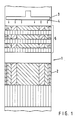
- Column 1 has an exchange part 2 with packing bodies arranged one above the other.
- the replacement part could also consist of a filling material, for example rings or saddles.
- liquid pre-distributor 3 e.g. a box distributor with feed points 4 arranged.
- the fine distributor underneath consists of a layer 5 with a structured structure, whereby two stacked structures are rotated 90 ° against each other.
- the height and number of the individual distributor packing bodies is calculated from the given rough distribution, the desired fine distribution and the geometric structure of the packing bodies, in particular the angle of the falling lines.
- the number of partial flows be increased by a factor of 4 compared to the pre-distribution and below that Assuming a quadratic pre-distribution, two packing bodies rotated by 90 ° must be used. If the fine distribution is again to be square (edge length b), the height h of the packing body is measured as follows: where ⁇ is the angle between the main flow directions of the partial flows.
- the height of a pair of packing bodies decreases according to a geometric series, the height of the top pair being calculated according to the equation above.
- 2a schematically shows two lamellae 6a and 6b of a distributor packing body with a liquid feed point 7.
- the liquid flow splits into two partial flows 7a and 7b, which essentially flow down along the falling lines f of the corresponding lamellae 6a and 6b.
- 2b shows the experimentally determined result with regard to the escaping liquid quantities 8a and 8b.
Landscapes
- Chemical & Material Sciences (AREA)
- Chemical Kinetics & Catalysis (AREA)
- Engineering & Computer Science (AREA)
- Thermal Sciences (AREA)
- Physics & Mathematics (AREA)
- General Chemical & Material Sciences (AREA)
- Oil, Petroleum & Natural Gas (AREA)
- Analytical Chemistry (AREA)
- Mechanical Engineering (AREA)
- General Engineering & Computer Science (AREA)
- Organic Chemistry (AREA)
- Vaporization, Distillation, Condensation, Sublimation, And Cold Traps (AREA)
- Physical Or Chemical Processes And Apparatus (AREA)
Applications Claiming Priority (2)
| Application Number | Priority Date | Filing Date | Title |
|---|---|---|---|
| CH393686 | 1986-10-02 | ||
| CH3936/86 | 1986-10-02 |
Publications (1)
| Publication Number | Publication Date |
|---|---|
| EP0264581A1 true EP0264581A1 (fr) | 1988-04-27 |
Family
ID=4266681
Family Applications (1)
| Application Number | Title | Priority Date | Filing Date |
|---|---|---|---|
| EP87112397A Withdrawn EP0264581A1 (fr) | 1986-10-02 | 1987-08-26 | Dispositif de distribution des liquides pour des colonnes de transfert de matière et de chaleur |
Country Status (3)
| Country | Link |
|---|---|
| EP (1) | EP0264581A1 (fr) |
| AU (1) | AU7928287A (fr) |
| BR (1) | BR8705113A (fr) |
Cited By (8)
| Publication number | Priority date | Publication date | Assignee | Title |
|---|---|---|---|---|
| FR2656681A1 (fr) * | 1989-12-29 | 1991-07-05 | Hamon | Dispositif de refrigeration de fluide pour refrigerant atmospherique. |
| EP0837725A1 (fr) * | 1995-07-08 | 1998-04-29 | Basf Aktiengesellschaft | Procede de rectification sous vide pousse pour extraire des substances pures contenues dans des melanges de substances a point d'ebullition eleve et a forte sensibilite a la temperature et a l'air, qui exigent un fort pourvoir de separation, et colonnes adaptees a ce procede |
| RU2133634C1 (ru) * | 1994-09-28 | 1999-07-27 | Зульцер Хемтех Аг | Распределитель жидкости для колонн |
| RU2134150C1 (ru) * | 1998-04-07 | 1999-08-10 | Кубанский государственный технологический университет | Циклонный скруббер |
| DE10010810A1 (de) * | 2000-03-08 | 2001-09-13 | Montz Gmbh Julius | Flüssigkeitsverteiler und Verfahren zum Betreiben |
| US6294053B1 (en) * | 1997-11-17 | 2001-09-25 | L'air Liquide, Societe, Anonyme Pour L'etude Et L'exploitation Des Procedes Georges Claude | Liquid dispenser for oscillating distilling column, and corresponding distilling column |
| DE102009036144A1 (de) * | 2009-08-05 | 2011-02-10 | Raschig Gmbh | Anstaukolonne |
| CN110913967A (zh) * | 2017-03-31 | 2020-03-24 | 制药流体股份有限公司 | 流动分配器 |
Families Citing this family (1)
| Publication number | Priority date | Publication date | Assignee | Title |
|---|---|---|---|---|
| CN105233516A (zh) * | 2015-10-09 | 2016-01-13 | 江苏华益科技有限公司 | 一种基于高通量规整填料支撑的大通量填料塔 |
Citations (4)
| Publication number | Priority date | Publication date | Assignee | Title |
|---|---|---|---|---|
| GB498774A (en) * | 1938-01-19 | 1939-01-13 | Heinrich Brune | Improvements in and relating to tower-like washing or distillation apparatus and the like |
| US2490080A (en) * | 1944-05-19 | 1949-12-06 | Francis L Melvill | Contacting apparatus |
| JPS5435876A (en) * | 1977-07-21 | 1979-03-16 | Binks Mfg Co | Method and apparatus for removing pollutants from gas |
| EP0069241A1 (fr) * | 1981-07-08 | 1983-01-12 | Kühni AG | Garniture pour colonnes d'échange de matières et procédé de fabrication de la garniture |
-
1987
- 1987-08-26 EP EP87112397A patent/EP0264581A1/fr not_active Withdrawn
- 1987-10-01 AU AU79282/87A patent/AU7928287A/en not_active Abandoned
- 1987-10-01 BR BR8705113A patent/BR8705113A/pt unknown
Patent Citations (4)
| Publication number | Priority date | Publication date | Assignee | Title |
|---|---|---|---|---|
| GB498774A (en) * | 1938-01-19 | 1939-01-13 | Heinrich Brune | Improvements in and relating to tower-like washing or distillation apparatus and the like |
| US2490080A (en) * | 1944-05-19 | 1949-12-06 | Francis L Melvill | Contacting apparatus |
| JPS5435876A (en) * | 1977-07-21 | 1979-03-16 | Binks Mfg Co | Method and apparatus for removing pollutants from gas |
| EP0069241A1 (fr) * | 1981-07-08 | 1983-01-12 | Kühni AG | Garniture pour colonnes d'échange de matières et procédé de fabrication de la garniture |
Non-Patent Citations (1)
| Title |
|---|
| DERWENT JAPANESE PATENTS REPORT, Band 79, Nr. 45, Teil: Chemical Engineering, Seite 2; & JP-A-79 035 876 (GLITSCH INC.) 06-11-1979 * |
Cited By (9)
| Publication number | Priority date | Publication date | Assignee | Title |
|---|---|---|---|---|
| FR2656681A1 (fr) * | 1989-12-29 | 1991-07-05 | Hamon | Dispositif de refrigeration de fluide pour refrigerant atmospherique. |
| EP0437133A1 (fr) * | 1989-12-29 | 1991-07-17 | Societe Hamon | Dispositif de réfrigération de fluide pour réfrigérant atmosphérique |
| RU2133634C1 (ru) * | 1994-09-28 | 1999-07-27 | Зульцер Хемтех Аг | Распределитель жидкости для колонн |
| EP0837725A1 (fr) * | 1995-07-08 | 1998-04-29 | Basf Aktiengesellschaft | Procede de rectification sous vide pousse pour extraire des substances pures contenues dans des melanges de substances a point d'ebullition eleve et a forte sensibilite a la temperature et a l'air, qui exigent un fort pourvoir de separation, et colonnes adaptees a ce procede |
| US6294053B1 (en) * | 1997-11-17 | 2001-09-25 | L'air Liquide, Societe, Anonyme Pour L'etude Et L'exploitation Des Procedes Georges Claude | Liquid dispenser for oscillating distilling column, and corresponding distilling column |
| RU2134150C1 (ru) * | 1998-04-07 | 1999-08-10 | Кубанский государственный технологический университет | Циклонный скруббер |
| DE10010810A1 (de) * | 2000-03-08 | 2001-09-13 | Montz Gmbh Julius | Flüssigkeitsverteiler und Verfahren zum Betreiben |
| DE102009036144A1 (de) * | 2009-08-05 | 2011-02-10 | Raschig Gmbh | Anstaukolonne |
| CN110913967A (zh) * | 2017-03-31 | 2020-03-24 | 制药流体股份有限公司 | 流动分配器 |
Also Published As
| Publication number | Publication date |
|---|---|
| BR8705113A (pt) | 1988-05-24 |
| AU7928287A (en) | 1988-04-14 |
Similar Documents
| Publication | Publication Date | Title |
|---|---|---|
| DE2943687C2 (de) | Trogartige Vorrichtung zum Sammeln und Verteilen der Flüssigkeit für eine Gegenstromkolonne | |
| EP0151693B1 (fr) | Colonne d'échange de matière | |
| EP0112978B1 (fr) | Distributeur de liquide pour une colonne d'échange de masse et ou de chaleur | |
| EP0282753B1 (fr) | Dispositif pour la distribution uniforme d'un liquide sur des parties d'échanges d'une colonne d'échange de matière et de chaleur | |
| EP0118029B1 (fr) | Dispositif pour la distribution gravimétrique de liquide pour une colonne d'échange de masse et de chaleur | |
| DE2919462C2 (de) | Vorrichtung zum gleichmäßigen Verteilen von Flüssigkeiten auf Kolonnenflächen | |
| DE69412578T2 (de) | Hochleistungswanne für gas-flüssigkeitskontaktvorrichtung | |
| DE2442603A1 (de) | Dampf-fluessigkeitskontaktverfahren und vorrichtung zur durchfuehrung des verfahrens | |
| DE10010810A1 (de) | Flüssigkeitsverteiler und Verfahren zum Betreiben | |
| EP0231841A1 (fr) | Dispositif pour la distribution uniforme d'un liquide contenant des matières solides sur une section transversale | |
| DE68926604T2 (de) | Flüssigkeitsverteiler für einen Füllkörperturm | |
| EP0925109B1 (fr) | Chicanes pour colonnes d'echange de substance | |
| DE69027693T2 (de) | Doppelstöckiger Verteiler | |
| EP0462049B1 (fr) | Dispositif pour amasser et mélanger des liquides dans une colonne à contre-courant | |
| DE10026064C1 (de) | Flüssigkeitsverteilerkörper für Stoff- und Wärmeaustauschkolonnen | |
| EP0232759B1 (fr) | Distributeur à ajutage tubulaire pour une phase dispersée dans une colonne d'extraction de liquide-liquide, dans une colonne à bulles de gaz-liquide et dans une colonne de réaction | |
| CH646877A5 (de) | Fluessigkeitsverteiler fuer stoffaustauschkolonnen. | |
| WO2017211790A1 (fr) | Fond pour une colonne d'échange de matières, colonne d'échange de matières et utilisation du fond | |
| DE3902275A1 (de) | Fluessigkeitsverteiler | |
| DE10210683B4 (de) | Einsatzelement für Flüssigkeitsverteilerkörper für Stoff- und Wärmeaustauschkolonnen | |
| DE3150350A1 (de) | "fluessigkeitsverteiler fuer einrichtungen der chemischen verfahrenstechnik" | |
| CH662515A5 (en) | Built-in element for mass transfer columns | |
| CH659401A5 (en) | Mass transfer column | |
| DD275619A1 (de) | Fluessigkeitsverteilereinrichtung mit dampfabfuehrungssektion fuer gegenstromfallfilterverdampfer | |
| DE8300693U1 (de) | Flüssigkeitsverteiler für eine Stoff- und Wärmeaustauschkolonne |
Legal Events
| Date | Code | Title | Description |
|---|---|---|---|
| PUAI | Public reference made under article 153(3) epc to a published international application that has entered the european phase |
Free format text: ORIGINAL CODE: 0009012 |
|
| AK | Designated contracting states |
Kind code of ref document: A1 Designated state(s): BE DE FR GB IT NL SE |
|
| STAA | Information on the status of an ep patent application or granted ep patent |
Free format text: STATUS: THE APPLICATION IS DEEMED TO BE WITHDRAWN |
|
| 18D | Application deemed to be withdrawn |
Effective date: 19881028 |
|
| RIN1 | Information on inventor provided before grant (corrected) |
Inventor name: ZUIDERWEG, FREDERIK JOHANNES, PROF.DR. |