EP0264601A2 - Machine à mouler par injection les matières plastiques et ordinateur et dispositif de visualisation correspondants - Google Patents
Machine à mouler par injection les matières plastiques et ordinateur et dispositif de visualisation correspondants Download PDFInfo
- Publication number
- EP0264601A2 EP0264601A2 EP87113069A EP87113069A EP0264601A2 EP 0264601 A2 EP0264601 A2 EP 0264601A2 EP 87113069 A EP87113069 A EP 87113069A EP 87113069 A EP87113069 A EP 87113069A EP 0264601 A2 EP0264601 A2 EP 0264601A2
- Authority
- EP
- European Patent Office
- Prior art keywords
- injection molding
- display device
- molding machine
- mold
- data display
- Prior art date
- Legal status (The legal status is an assumption and is not a legal conclusion. Google has not performed a legal analysis and makes no representation as to the accuracy of the status listed.)
- Withdrawn
Links
Images





Classifications
-
- B—PERFORMING OPERATIONS; TRANSPORTING
- B23—MACHINE TOOLS; METAL-WORKING NOT OTHERWISE PROVIDED FOR
- B23Q—DETAILS, COMPONENTS, OR ACCESSORIES FOR MACHINE TOOLS, e.g. ARRANGEMENTS FOR COPYING OR CONTROLLING; MACHINE TOOLS IN GENERAL CHARACTERISED BY THE CONSTRUCTION OF PARTICULAR DETAILS OR COMPONENTS; COMBINATIONS OR ASSOCIATIONS OF METAL-WORKING MACHINES, NOT DIRECTED TO A PARTICULAR RESULT
- B23Q1/00—Members which are comprised in the general build-up of a form of machine, particularly relatively large fixed members
- B23Q1/0009—Energy-transferring means or control lines for movable machine parts; Control panels or boxes; Control parts
-
- B—PERFORMING OPERATIONS; TRANSPORTING
- B29—WORKING OF PLASTICS; WORKING OF SUBSTANCES IN A PLASTIC STATE IN GENERAL
- B29C—SHAPING OR JOINING OF PLASTICS; SHAPING OF MATERIAL IN A PLASTIC STATE, NOT OTHERWISE PROVIDED FOR; AFTER-TREATMENT OF THE SHAPED PRODUCTS, e.g. REPAIRING
- B29C45/00—Injection moulding, i.e. forcing the required volume of moulding material through a nozzle into a closed mould; Apparatus therefor
- B29C45/17—Component parts, details or accessories; Auxiliary operations
- B29C45/1756—Handling of moulds or mould parts, e.g. mould exchanging means
-
- B—PERFORMING OPERATIONS; TRANSPORTING
- B29—WORKING OF PLASTICS; WORKING OF SUBSTANCES IN A PLASTIC STATE IN GENERAL
- B29C—SHAPING OR JOINING OF PLASTICS; SHAPING OF MATERIAL IN A PLASTIC STATE, NOT OTHERWISE PROVIDED FOR; AFTER-TREATMENT OF THE SHAPED PRODUCTS, e.g. REPAIRING
- B29C45/00—Injection moulding, i.e. forcing the required volume of moulding material through a nozzle into a closed mould; Apparatus therefor
- B29C45/17—Component parts, details or accessories; Auxiliary operations
- B29C45/1774—Display units or mountings therefor; Switch cabinets
-
- B—PERFORMING OPERATIONS; TRANSPORTING
- B29—WORKING OF PLASTICS; WORKING OF SUBSTANCES IN A PLASTIC STATE IN GENERAL
- B29C—SHAPING OR JOINING OF PLASTICS; SHAPING OF MATERIAL IN A PLASTIC STATE, NOT OTHERWISE PROVIDED FOR; AFTER-TREATMENT OF THE SHAPED PRODUCTS, e.g. REPAIRING
- B29C45/00—Injection moulding, i.e. forcing the required volume of moulding material through a nozzle into a closed mould; Apparatus therefor
- B29C45/17—Component parts, details or accessories; Auxiliary operations
- B29C45/1756—Handling of moulds or mould parts, e.g. mould exchanging means
- B29C2045/1757—Handling of moulds or mould parts, e.g. mould exchanging means common exchange means for several injection machines
Definitions
- the invention relates to an injection molding machine according to the preamble of claim 1.
- the data display device and the input keyboards are spatially separated from the computer of the injection molding machine. This is equivalent to the resolution of the usual structural unit consisting of the control cabinet with its data display device and the input keyboards.
- the liberation of the control cabinet from the input keyboards has the advantage, among other things, that the computer in the control cabinet can be hermetically sealed (multi-microprocessor system with color monitor, plastics plastics 6/83). Proceeding from this, the object of the invention is to further develop a known injection molding machine of this type in the direction of an easy-to-use arrangement of the control keyboards and the data display device in a control station which is located in the control area (E in FIG.
- the operating streets can be cleaned and cleaned up with clearing devices after a relatively short time.
- the injection molding machine has a horizontally closing mold closing unit 17 and an injection molding unit 117 on a rectangular machine base 11 with a rectangular footprint M.
- the injection molding unit 117 can be placed or removed with the horizontal injection axis xx of its plasticizing cylinder 52 onto the injection mold S which can be clamped in the mold closing unit 17 and is guided on stationary horizontal columns by means of a carrier block 117a.
- a protective cover * of rectangular cross section encloses the injection molding unit in the area of its drive units.
- the drive device for the movable mold carrier 28 is covered by stationary protective covers 17 ', under which protective slides 17' can be inserted, which otherwise cover the mold clamping unit 17, namely up to the stationary mold carrier 12 (FIG. 34). * (117b in Fig. 3-5)
- the data display device H can be pivoted by means of a horizontal swivel arm 128 from a use position lying in an operating area E into a rest position located within the footprint M of the injection molding machine and vice versa.
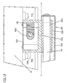
- the swivel arm 128 is pivotally mounted on a support column 122 which is supported on an upper edge 11a of the operator-side, vertical wall 11a of the cuboid machine base made of sheet steel, which is bent into the horizontal (FIGS. 4, 5, 13).
- Figs. 3-5 in connection with Figs. 1, 2 it can also be seen that the data display device in the rest position with a housing 129a containing the associated electronics overlaps the protective wall 117b with the horizontal wall.
- the screen 134 of the data display device H flanked by side input keyboards 135 is arranged in a rectangular frame 129, as can be seen in particular from FIG. 6.
- the height of this frame 129 corresponds approximately to the height of the housing 129a (Fig. 5,6).
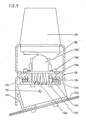
- the data display device H is connected to the swivel arm 128 via a rotary bearing 130, as is shown in particular in FIGS. 3-9 recognizable.
- the rotary bearing 130 comprises a bearing ring 130a of the swivel arm 128 and a stop disk 130e fastened to the bearing ring 130 and a damping element 130c.
- the mounting screws are labeled 130b and 130f.
- the upper wall of the housing 129a containing the electronics is rotatably supported directly on the stop disk 130e (Fig. 8,9) via the damping element 130c (Fig. 8,9).
- FIG. 7a, 8a, 9 show a rotary-swivel connection of the data display device with the swivel arm, in which a swivel device is inserted between the upper wall of the housing 129a and the swivel bearing 130, which enables the swivel device to be rotated by means of the swivel bearing 130
- the swivel device comprises a swivel bearing piece 149, with the aid of which the data display device H is mounted on the axle pin 150.
- the latter is in a bearing 148 added, which engages behind the damping element 130c of the rotary bearing 130.
- the data display device H is locked in the respective pivot position by means of a clamping lever 150a in that the bearing piece 148 is clamped to the pivot bearing piece 149.
- the rotation of the data display device H is caused by a tongue 133 in FIG. 7 which is punched and bent from the upper wall of the housing 129a (example of FIGS. 3-8) or from the upper wall of the bearing piece 148 (FIGS. 7a, 8a, 9) , 8 and 133 a in Fig. 7a, 8a, 9 limited.
- This tongue works together with stop edges 130h of the stop disk 130e.
- the supply lines 132a leading to the data display device H are accommodated in a protective hose 132 which are laid in the support column 122 and in the swivel arm 128.
- the supply lines running horizontally in the swivel arm 128 are deflected at the transition to the data display device in an angle piece 132b, as can be seen in particular from FIGS. 8, 8a.
- the tubular profile of the swivel arm 128 is provided on the end face with a cover 128a.
- a signal lamp 139 is placed coaxially to the pivot bearing 130 on the swivel arm 128.
- the legs 122a of the profile of the support column 122, which profile is closed with a cover plate 122i (FIG. 13), are screwed to the platform 90 (FIG. 5.13) of the machine base 11.
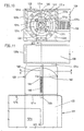
- the support column 122 which has a U-profile, has an end section 122 ′ of larger cross-section that overlaps a protective door 121 (FIGS. 11, 12).
- a pivot bearing 131 for the swivel arm 128 and a device L are arranged, by means of which the protective door 121, which can be moved parallel to the spray axis xx, can be locked.
- the device L is designed such that a lock occurs when the visual display device H is in the path of movement of the protective door 121.
- the front surface of the support column 122 lies in the end section 122 ⁇ and the front surface of the protective door 121 lies in a common vertical plane.
- the rest of the front surface of the support column 122 lies in the vertical plane aa (Fig. 4, 12) of the operator-side wall 11a of the machine base 11 (Fig. 4-5).
- the guide columns 147 rigidly connected to the protective door 121 slide in sliding bushes 147a which are received in projections 122e of the web 122b (FIGS. 12, 13).
- the protective door made of sheet steel is provided with a viewing window 121c on its front surface.
- the stationary guide columns 147 are spaced from one another, so that the protective door 121 is guided securely (FIGS. 3, 12). In the closed position, this adjoins a stationary carrier plate 127 for an operating keyboard 126 lying in the plane aa (FIG. 4.13), as shown in FIGS. 3.4 recognizable.
- the U-section forming the end section 122 ⁇ comprises the web 122b ⁇ and the legs 122a ⁇ .
- An inner bearing flange 122d with horizontal sliding surfaces 122d ⁇ is formed on the upper end of this web and this leg.
- the swivel arm 128 is rotatably supported by means of a bearing ring 131a fastened to it on a control disk 131c fastened to this bearing ring.
- a radial flange of the bearing ring 131a lies on the upper sliding surface 122d ⁇ and the control disk 131c rotatably on the lower sliding surface 122d ⁇ , as can be seen in particular from FIG. 12.
- the legs 122a ⁇ are penetrated by a friction screw 155.
- these legs 122a ⁇ can be pre-stressed. Due to the preload, the inner, circular, vertical sliding surface 122d ⁇ (FIG. 12) of the bearing flange 122d is braced with the corresponding sliding surface of the bearing ring 131a and the pivot arm 128 is thereby rotatably inhibited in the set pivot bearing under friction.
- An axis 143 is mounted in the legs 122a ⁇ in the vicinity of the web 122b ⁇ (FIGS. 11, 12).
- a locking lever 142 of the device L is pivotably arranged on this axis 143 in the plane of symmetry of the support arm 122. The locking lever 142 can be controlled with the aid of a control profile arranged on the circumference of the control disk 131c.
- the locking lever 142 rests with its upper arm 142a on the end face of the control profile under the action of a spring 145.
- the spring 145 is arranged in a vertical bore of the web and engages the arm 142a by means of a piece 144. If the contact edge of the locking lever in section 131f (FIG. 10) is in contact, as is the case in FIGS. 10, 12, the free end 142b of the locking lever 142 engages behind a tab 121b which is bent out at right angles from the edge 121a of the protective door 121 . 6, 10 to 12, the swivel arm runs parallel to the vertical, operator-side wall 11a of the machine base 11 or to the spray axis xx.
- the end edge of the lever arm 142a runs onto the control edge 131e or 131g.
- the control edges mentioned form an angle of approximately 45 ° to the radial.
- the locking lever 142 is transferred from the locking position according to FIG. 12 (solid lines) to an unlocking position, which is indicated in FIG. 12 by dashed lines before it runs onto one of the stop edges 131d or 131i.
- the lever arm 142a rests on the stop edge 131d when the data display device is in the rest position and on the stop edge 131i when it is in the use position. Both extreme positions can be seen in Fig. 4,5.
- the bearing flange 122d is not closed to form a complete circle, but leaves a radial slot with the inside width z (FIG. 10) open, through which the protective tube 132 can be inserted into the support column 122 during assembly.
- the bearing ring 131a is fastened to the swivel arm 128 by means of fastening screws 131b and the control disk 131c is fastened to the bearing ring 131a by means of fastening screws 131k.
- a protective cover 124 arranged in the plane a-a of the vertical wall 11a of the machine base 11 is fastened to the support column 122. This extends to the level of the data display device H which is in the rest position and which can be supported on this protective cover 124.
- rubber buffers 152 located at the bottom of the housing 129a rest on a right-angled upper edge of the protective cover 124.
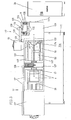
- the injection molding machines are lined up on both sides of a linear path 45 on the end face.
- the injection system also includes a mold depot 44, a roller table 49 for the removal of injection molds S and a station 50 for the removal of collection containers filled with injection molded parts.
- the rail vehicle 27 can be moved alternately in connection positions for transferring or taking over the injection mold S or the plasticizing cylinder 52 or the injection parts on the mold depot 44 and on the injection molding machines.
- the injection molding machines are arranged in parallel with respect to their injection axes xx and at a distance from the web 45 which enables the connection positions.
- the injection molding machines located on one side of the web 45 are arranged mirror-symmetrically to the injection molding machines located on the other side. Thus, the rear sides r of all injection molding machines face the web. If the injection molding machines are of different sizes, their operating sides b are each at a different distance from web 45.
- the operator-side vertical walls 11a of the machine feet 11 of the injection molding machines together with the protective covers arranged on them 124, 17 ⁇ and protective doors 17 ⁇ and 121 (FIGS. 3-5) a delimitation of the operating areas E from a danger zone D, indicated by hatching in the diagrams of FIGS. 1, 2.
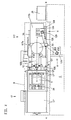
- the injection molding machines and the web 45 are enclosed in the latter. In the case of two production systems arranged next to one another (FIG.
- the middle service line E ⁇ is delimited on both sides by the danger zones D by the operator-side vertical walls 11a and the switch cabinets 38 arranged between the end faces of the injection molding machine.
- the mold changing devices recognizable in FIGS. 1 and 2, which are known from the earlier patent applications P 36 17 094.1-16 and P 36 26 488.1, are to be mentioned only briefly below.
- a shuttle table 19 can be moved about a mold depth parallel to the spray axis xx at the rear of each injection molding machine in such a way that its mold guide G. (FIG. 1) can alternately form a change path with a mold guide G in the mold clamping space F.
- This mold guide G ⁇ of the changing table 19 can also form a transport path for taking over an injection mold S from the changing table 19 to the rail vehicle 27 and vice versa with a mold guide G ⁇ of the rail vehicle 27 movable in the connecting position.
- the mold guide G ⁇ of the rail vehicle 27 moved in the connection position to the mold depot 44 can form a transport path for taking over an injection mold S from the parking space 44a onto the rail vehicle and vice versa with the mold guide of a parking space 44a.
- the mold guide G ⁇ and a mold shifting device are rotatably mounted on a bearing plate of the rail vehicle 27, so that it can optionally be moved to an injection molding machine on one or the other side of the web 45 in the connecting position.
- the rail vehicle 27 also serves as a shuttle table with two parking spaces, which are formed on a rotatable carrier plate are.
- the parking spaces mentioned can optionally be filled with injection molds S or plasticizing cylinders 52.
- the mold guides G ⁇ of the rail vehicle 27 ⁇ can optionally form transport tracks for transferring injection molds S or plasticizing cylinders 52 with the mold guides G of the mold clamping spaces F or with guides G IV for plasticizing cylinders 52 or with the mold guides G ′′′ of the parking spaces 44a of the mold deposit 44.
- the rail vehicle 27 (solid lines) is in the connection position on a shuttle table 19 of an injection molding machine adjacent to the mold depot 44.
- An injection mold S has just been transferred from this shuttle table into the mold clamping area of this injection molding machine and is in the working position.
- the replaced injection mold is currently being transferred from the second parking space of the shuttle table 19 to the transport vehicle, specifically on a transport path which is formed by the mold guide G ⁇ of the shuttle table and the mold guide G ⁇ of the transport vehicle.
- the position of the transport vehicle 27 is indicated at the top when it is in the connection position at a depot 44a.
- the transport vehicle 27 is in the connected position at a depot parking space 44a, its mold guide G G forming a transport path with the mold guide G′′′ of this depot parking space 44a.
- the injection mold located on the transport vehicle 27 is just starting to be transferred to the depot 44a.
- the transport vehicle 27 is indicated by dashed lines in a connection position to the shuttle table.
- the new injection mold is already in the mold clamping area F in.
- the injection mold to be removed stands before the transfer from the second parking space of the shuttle table 19 to the transport vehicle 27.
- the data display devices of both injection molding systems are partly in the use position and partly in the rest position.
- the operator's workplace is indicated with a "P".
- the granulate containers 51 of the injection molding machines are indicated.
- the transport vehicle 27 is simultaneously designed as a shuttle table with two parking spaces.
- the transport vehicle is moved to an injection molding machine to change the plasticizing cylinder 52 into a connection position to the mold guide G IV .
- the plasticizing cylinder is being transferred from the injection molding machine via the guide G IV to the mold guide of the adjacent parking space of the transport vehicle 27 ⁇ .
- the carrier plate of the transport vehicle 27 is rotated, as indicated in FIG. 2 by dashed lines, so that the plasticizing cylinder 52 ⁇ located on the other parking space of the transport vehicle and brought about by the depot 44 can be replaced in the injection molding machine.
- the position of the transport vehicle 27 ⁇ is indicated when it is in the connecting position on the mold deposit 44, which can also accommodate plasticizing cylinder 52.
- the axis of symmetry of the injection molding system is indicated by yy.
- an injection molding machine 38 is assigned to the associated computer.
- These control cabinets 38 are each positioned on the end faces of the machine storage areas M. This results in an even better shielding of the operating areas E (FIG. 4) combined according to the length of the web 45 to form a safe and relatively free operating street E ⁇ from the danger area D.
- This screening means that an operator can be accidentally or illegally transferred from the operating street E ⁇ in danger zone D considerably more difficult. Tampering with the injection molding units 117 or mold closing units 17 (FIG. 2, bottom left) in operation is prevented by the protective covers 17deck, 124 and the protective doors 17 ⁇ and 121.
- the protective door 121 can indeed be moved out of its closed position when the data display device H is not in the path of movement of the protective door. In this case, however, when the safety door is opened by other safety devices, the operation of the injection molding machine is shut down as soon as the safety door has moved a few centimeters from its closed position.
Landscapes
- Engineering & Computer Science (AREA)
- Mechanical Engineering (AREA)
- Manufacturing & Machinery (AREA)
- Injection Moulding Of Plastics Or The Like (AREA)
Applications Claiming Priority (2)
| Application Number | Priority Date | Filing Date | Title |
|---|---|---|---|
| DE3632449 | 1986-09-24 | ||
| DE19863632449 DE3632449A1 (de) | 1986-09-24 | 1986-09-24 | Kunststoff-spritzgiessmaschine mit zugehoerigem computer und datensichtgeraet |
Related Child Applications (2)
| Application Number | Title | Priority Date | Filing Date |
|---|---|---|---|
| EP90102547A Division EP0382232B1 (fr) | 1986-09-24 | 1987-09-08 | Machine à injecter les plastiques avec ordinateur et écran de visualisation associés montés sur un bras pivotable |
| EP90102547.8 Division-Into | 1987-09-08 |
Publications (2)
| Publication Number | Publication Date |
|---|---|
| EP0264601A2 true EP0264601A2 (fr) | 1988-04-27 |
| EP0264601A3 EP0264601A3 (fr) | 1989-07-05 |
Family
ID=6310253
Family Applications (2)
| Application Number | Title | Priority Date | Filing Date |
|---|---|---|---|
| EP90102547A Expired - Lifetime EP0382232B1 (fr) | 1986-09-24 | 1987-09-08 | Machine à injecter les plastiques avec ordinateur et écran de visualisation associés montés sur un bras pivotable |
| EP87113069A Withdrawn EP0264601A3 (fr) | 1986-09-24 | 1987-09-08 | Machine à mouler par injection les matières plastiques et ordinateur et dispositif de visualisation correspondants |
Family Applications Before (1)
| Application Number | Title | Priority Date | Filing Date |
|---|---|---|---|
| EP90102547A Expired - Lifetime EP0382232B1 (fr) | 1986-09-24 | 1987-09-08 | Machine à injecter les plastiques avec ordinateur et écran de visualisation associés montés sur un bras pivotable |
Country Status (5)
| Country | Link |
|---|---|
| US (1) | US4775309A (fr) |
| EP (2) | EP0382232B1 (fr) |
| JP (1) | JPS63107534A (fr) |
| AT (1) | ATE88130T1 (fr) |
| DE (2) | DE3632449A1 (fr) |
Cited By (5)
| Publication number | Priority date | Publication date | Assignee | Title |
|---|---|---|---|---|
| EP0336249A3 (fr) * | 1988-04-02 | 1991-04-24 | Karl Hehl | Machine à mouler par injection à armoire de commande et unité d'entrée |
| EP0349807A3 (fr) * | 1988-07-07 | 1991-07-17 | Karl Hehl | Machine d'injection de matière plastique |
| DE4236147C1 (de) * | 1992-10-27 | 1994-04-07 | Karl Hehl | Kunststoff-Spritzgießmaschine mit Schaltschrank und Datensichtgerät |
| EP0700767A4 (fr) * | 1994-02-24 | 1997-03-05 | Fanuc Ltd | Presse a injecter munie d'un ecran |
| EP0849060A1 (fr) * | 1996-10-24 | 1998-06-24 | Husky Injection Molding Systems Ltd. | Dispositif à mouler par injection |
Families Citing this family (19)
| Publication number | Priority date | Publication date | Assignee | Title |
|---|---|---|---|---|
| US5017121A (en) * | 1987-12-30 | 1991-05-21 | Karl Hehl | Injection molding machine comprising a protective covering |
| DE3744523C1 (de) * | 1987-12-30 | 1989-06-08 | Karl Hehl | Schutzabdeckung an einer Kunststoff-Spritzgiessmaschine |
| JP2627814B2 (ja) * | 1990-09-20 | 1997-07-09 | ファナック株式会社 | ディスプレイ器を備えた射出成形機 |
| US5391070A (en) * | 1990-11-02 | 1995-02-21 | Fanuc Ltd | Injection molding machine equipped with a movable display unit |
| JP2627818B2 (ja) * | 1990-11-02 | 1997-07-09 | ファナック株式会社 | ディスプレイ器を備えた射出成形機 |
| JP2777853B2 (ja) * | 1992-06-30 | 1998-07-23 | ファナック株式会社 | 表示兼手動入力装置を備えた機械装置 |
| DE4315902A1 (de) * | 1993-05-12 | 1994-11-24 | Boy Gmbh Dr | Bedieneinheit für eine Spritzgießmaschine |
| DE19725544A1 (de) * | 1997-06-17 | 1998-12-24 | Illig Maschinenbau Adolf | Vorrichtung zum Verformen einer Folienbahn oder einer Platte aus thermoplastischem Kunststoff |
| US6612519B1 (en) | 1999-11-02 | 2003-09-02 | Axis Usa, Inc. | Methods and apparatus for winding electric machine cores |
| JP2003011160A (ja) * | 2001-07-05 | 2003-01-15 | Toshiba Mach Co Ltd | 射出成形機 |
| DE10354879A1 (de) * | 2003-11-24 | 2005-06-30 | Siemens Ag | Abdeckbares Display für Geräte in der Automatisierungstechnik |
| US7960097B2 (en) * | 2007-10-30 | 2011-06-14 | Triquint Semiconductor, Inc. | Methods of minimizing etch undercut and providing clean metal liftoff |
| JP4575972B2 (ja) * | 2008-06-23 | 2010-11-04 | 平田機工株式会社 | 組付部品の解体装置 |
| JP6734326B2 (ja) * | 2018-07-12 | 2020-08-05 | ファナック株式会社 | 射出成形機 |
| WO2020209948A1 (fr) * | 2019-04-11 | 2020-10-15 | Canon Virginia, Inc. | Système de moulage par injection doté de dispositifs de transport servant à insérer ou éjecter des moules |
| DE102020103659B3 (de) * | 2020-02-12 | 2021-03-18 | Kraussmaffei Technologies Gmbh | Spritzeinheit für das Mehrkomponenten-Spritzgießen |
| CN116034007A (zh) * | 2020-08-07 | 2023-04-28 | 发那科株式会社 | 注射成型机 |
| JP2023048344A (ja) * | 2021-09-28 | 2023-04-07 | セイコーエプソン株式会社 | 射出成形システム |
| WO2022118302A1 (fr) * | 2021-12-08 | 2022-06-09 | Nazari Barsari Aghil | Dispositif rotatif pour produire des semelles de chaussure à l'aide d'une plate-forme centrale avec un mouvement de 360 degrés et une liberté de mouvement sectoriel manuel |
Family Cites Families (9)
| Publication number | Priority date | Publication date | Assignee | Title |
|---|---|---|---|---|
| US3909172A (en) * | 1969-01-29 | 1975-09-30 | British Industrial Plastics | Electrical control of machines |
| FR2386386A1 (fr) * | 1977-04-08 | 1978-11-03 | Million J | Support d'appareils de controle pour machines-outils |
| US4522247A (en) * | 1980-01-11 | 1985-06-11 | Olin Corporation | Infrared imaging for electromagnetic casting |
| USRE32596E (en) * | 1980-04-07 | 1988-02-09 | Olin Corporation | Head top surface measurement utilizing screen parameters in electromagnetic casting |
| DE3029629C2 (de) * | 1980-08-05 | 1982-08-26 | Karl 7298 Loßburg Hehl | Sicherheitsabdeckung für den Gießformbereich einer Kunststoff-Spritzgießmaschine |
| JPS60192610A (ja) * | 1984-03-14 | 1985-10-01 | Katashi Aoki | 射出成形機 |
| DE3617094A1 (de) * | 1986-05-21 | 1987-11-26 | Karl Hehl | Giessformwechseleinrichtung an einer gruppe von kunststoffspritzgiessmaschinen |
| DE3645163C2 (en) * | 1986-08-05 | 1992-02-13 | Karl 7298 Lossburg De Hehl | Changing mould for injection moulding |
| JPH043773Y2 (fr) * | 1986-08-07 | 1992-02-05 |
-
1986
- 1986-09-24 DE DE19863632449 patent/DE3632449A1/de active Granted
-
1987
- 1987-09-08 EP EP90102547A patent/EP0382232B1/fr not_active Expired - Lifetime
- 1987-09-08 EP EP87113069A patent/EP0264601A3/fr not_active Withdrawn
- 1987-09-08 AT AT90102547T patent/ATE88130T1/de not_active IP Right Cessation
- 1987-09-08 DE DE9090102547T patent/DE3785461D1/de not_active Expired - Fee Related
- 1987-09-21 US US07/099,260 patent/US4775309A/en not_active Expired - Fee Related
- 1987-09-24 JP JP62237575A patent/JPS63107534A/ja active Pending
Cited By (6)
| Publication number | Priority date | Publication date | Assignee | Title |
|---|---|---|---|---|
| EP0336249A3 (fr) * | 1988-04-02 | 1991-04-24 | Karl Hehl | Machine à mouler par injection à armoire de commande et unité d'entrée |
| EP0349807A3 (fr) * | 1988-07-07 | 1991-07-17 | Karl Hehl | Machine d'injection de matière plastique |
| DE4236147C1 (de) * | 1992-10-27 | 1994-04-07 | Karl Hehl | Kunststoff-Spritzgießmaschine mit Schaltschrank und Datensichtgerät |
| EP0700767A4 (fr) * | 1994-02-24 | 1997-03-05 | Fanuc Ltd | Presse a injecter munie d'un ecran |
| US5670186A (en) * | 1994-02-24 | 1997-09-23 | Fanuc Ltd. | Injection molding machine provided molding with a display unit |
| EP0849060A1 (fr) * | 1996-10-24 | 1998-06-24 | Husky Injection Molding Systems Ltd. | Dispositif à mouler par injection |
Also Published As
| Publication number | Publication date |
|---|---|
| ATE88130T1 (de) | 1993-04-15 |
| EP0382232A2 (fr) | 1990-08-16 |
| US4775309A (en) | 1988-10-04 |
| EP0382232A3 (fr) | 1991-04-24 |
| DE3785461D1 (de) | 1993-05-19 |
| EP0382232B1 (fr) | 1993-04-14 |
| JPS63107534A (ja) | 1988-05-12 |
| EP0264601A3 (fr) | 1989-07-05 |
| DE3632449C2 (fr) | 1989-07-20 |
| DE3632449A1 (de) | 1988-04-07 |
Similar Documents
| Publication | Publication Date | Title |
|---|---|---|
| EP0264601A2 (fr) | Machine à mouler par injection les matières plastiques et ordinateur et dispositif de visualisation correspondants | |
| EP0668817B1 (fr) | Machine de moulage par injection | |
| WO1994015049A1 (fr) | Dispositif de fermeture pour portes de boitiers ou de placards | |
| DE69412363T2 (de) | Schloss für einen Schubladenschrank | |
| DE69717561T2 (de) | Öffnungsmechanismus für koplanare Türen | |
| EP0142702B1 (fr) | Dispositif antivol pour skis | |
| EP0255598B1 (fr) | Tiroir de caisse | |
| DE19541758C2 (de) | Feststell- und Verriegelungsvorrichtung für schwenk- und verschiebbare Türen | |
| DE2737980B2 (de) | Vorrichtung zum Reinigen von Koksofentüren | |
| EP0095443A1 (fr) | Dispositif d'attelage | |
| DE8625531U1 (de) | Kunststoff-Spritzgießmaschine mit zugehörigem Computer und Datensichtgerät | |
| DE3537863A1 (de) | Verriegelungsvorrichtung fuer transportfahrzeuge fuer container oder paletten | |
| DE4300333C2 (de) | Tor mit einem in die Schließ- und Offenstellung verschiebbaren Torblatt | |
| DE3115479A1 (de) | Umsetzvorrichtung fuer ein regalfoerderzeug | |
| DE4240149C2 (de) | Riegelwerk | |
| EP0446598A1 (fr) | Attelage de remorquage, en particulier pour tracteur ou similaire avec prise de force arrière | |
| EP0698707B1 (fr) | Dispositif de verrouillage central pour chariot porte-outils | |
| DE2020061B2 (de) | Formschließeinheit für die Spritzgießform einer Spritzgießmaschine mit Schutzschiebern | |
| DE3744523C1 (de) | Schutzabdeckung an einer Kunststoff-Spritzgiessmaschine | |
| DE3135400A1 (de) | Sektional-tor | |
| DE3709088C2 (fr) | ||
| DE2237395A1 (de) | Glasschiebetuer, insbesondere fuer ganzglas-vitrinen | |
| DE4440083C1 (de) | Vorrichtung zum Führen von flächenbündigen Schiebeschranktüren | |
| EP0932125A1 (fr) | Dispositif avec un vantail pivotable, notamment pour un mécanisme d'encaissement dans une machine de vente | |
| DE3047433A1 (de) | Foerderwagen, dessen foerderbehaelter mit einem verriegelbaren deckel verschliessbar ist |
Legal Events
| Date | Code | Title | Description |
|---|---|---|---|
| PUAI | Public reference made under article 153(3) epc to a published international application that has entered the european phase |
Free format text: ORIGINAL CODE: 0009012 |
|
| AK | Designated contracting states |
Kind code of ref document: A2 Designated state(s): AT CH DE FR GB IT LI NL |
|
| PUAL | Search report despatched |
Free format text: ORIGINAL CODE: 0009013 |
|
| AK | Designated contracting states |
Kind code of ref document: A3 Designated state(s): AT CH DE FR GB IT LI NL |
|
| 17P | Request for examination filed |
Effective date: 19900104 |
|
| 17Q | First examination report despatched |
Effective date: 19910211 |
|
| STAA | Information on the status of an ep patent application or granted ep patent |
Free format text: STATUS: THE APPLICATION IS DEEMED TO BE WITHDRAWN |
|
| 18D | Application deemed to be withdrawn |
Effective date: 19911007 |