EP0264638A2 - Druckspüler für Wasserklosetts - Google Patents
Druckspüler für Wasserklosetts Download PDFInfo
- Publication number
- EP0264638A2 EP0264638A2 EP87113747A EP87113747A EP0264638A2 EP 0264638 A2 EP0264638 A2 EP 0264638A2 EP 87113747 A EP87113747 A EP 87113747A EP 87113747 A EP87113747 A EP 87113747A EP 0264638 A2 EP0264638 A2 EP 0264638A2
- Authority
- EP
- European Patent Office
- Prior art keywords
- flush valve
- valve
- flush
- button
- relief
- Prior art date
- Legal status (The legal status is an assumption and is not a legal conclusion. Google has not performed a legal analysis and makes no representation as to the accuracy of the status listed.)
- Granted
Links
- XLYOFNOQVPJJNP-UHFFFAOYSA-N water Substances O XLYOFNOQVPJJNP-UHFFFAOYSA-N 0.000 title claims abstract description 21
- 230000000979 retarding effect Effects 0.000 claims 1
- 238000011010 flushing procedure Methods 0.000 abstract description 33
- 230000000630 rising effect Effects 0.000 abstract description 2
- 238000007789 sealing Methods 0.000 abstract 2
- 238000000034 method Methods 0.000 description 15
- 238000005406 washing Methods 0.000 description 2
- 230000001934 delay Effects 0.000 description 1
- 238000010926 purge Methods 0.000 description 1
Images


Classifications
-
- E—FIXED CONSTRUCTIONS
- E03—WATER SUPPLY; SEWERAGE
- E03D—WATER-CLOSETS OR URINALS WITH FLUSHING DEVICES; FLUSHING VALVES THEREFOR
- E03D3/00—Flushing devices operated by pressure of the water supply system flushing valves not connected to the water-supply main, also if air is blown in the water seal for a quick flushing
- E03D3/02—Self-closing flushing valves
- E03D3/04—Self-closing flushing valves with piston valve and pressure chamber for retarding the valve-closing movement
-
- F—MECHANICAL ENGINEERING; LIGHTING; HEATING; WEAPONS; BLASTING
- F16—ENGINEERING ELEMENTS AND UNITS; GENERAL MEASURES FOR PRODUCING AND MAINTAINING EFFECTIVE FUNCTIONING OF MACHINES OR INSTALLATIONS; THERMAL INSULATION IN GENERAL
- F16K—VALVES; TAPS; COCKS; ACTUATING-FLOATS; DEVICES FOR VENTING OR AERATING
- F16K21/00—Fluid-delivery valves, e.g. self-closing valves
- F16K21/04—Self-closing valves, i.e. closing automatically after operation
- F16K21/06—Self-closing valves, i.e. closing automatically after operation in which the closing movement, either retarded or not, starts immediately after opening
- F16K21/10—Self-closing valves, i.e. closing automatically after operation in which the closing movement, either retarded or not, starts immediately after opening with hydraulic brake cylinder acting on the closure member
-
- F—MECHANICAL ENGINEERING; LIGHTING; HEATING; WEAPONS; BLASTING
- F16—ENGINEERING ELEMENTS AND UNITS; GENERAL MEASURES FOR PRODUCING AND MAINTAINING EFFECTIVE FUNCTIONING OF MACHINES OR INSTALLATIONS; THERMAL INSULATION IN GENERAL
- F16K—VALVES; TAPS; COCKS; ACTUATING-FLOATS; DEVICES FOR VENTING OR AERATING
- F16K21/00—Fluid-delivery valves, e.g. self-closing valves
- F16K21/04—Self-closing valves, i.e. closing automatically after operation
- F16K21/06—Self-closing valves, i.e. closing automatically after operation in which the closing movement, either retarded or not, starts immediately after opening
- F16K21/12—Self-closing valves, i.e. closing automatically after operation in which the closing movement, either retarded or not, starts immediately after opening with hydraulically-operated opening means; with arrangements for pressure relief before opening
Definitions
- the invention relates to a flush valve for water closets according to the preamble of claim 1.
- the relief valve has a closing plunger which is pressed into the closed position by a return spring acting directly on it and which can be moved into the open position on a flush valve button connected to the closing plunger.
- the invention therefore has for its object to provide a flush valve of the type mentioned which, even when the flush valve button is pressed vigorously, avoids a violent and splashing flushing process and automatically maintains a predetermined opening time and thus a predetermined flush volume even when the flush valve button is pressed only briefly.
- the invention also wants to make it possible, as with cisterns, to flush optionally with a flush valve with the usual large flush volume or, in certain cases, with a reduced, permitted small flush volume and also automatically maintain the small flush volume with the flush valve becomes.
- the opening speed of the flushing valve piston is determined by the difference in the cross sections of the two nozzle bores and can be slowed down to a desired extent the less the relief nozzle is dimensioned larger than the inlet nozzle. Even if the flush valve button is pressed for a short time Actuation is released again, the relief valve closes itself only when the flushing valve piston, which rises as a result of the pressure relief of the pressure compensation chamber and thereby carries the locking plunger, presses the locking plunger against the locking seat of the relief valve towards the end of its stroke. From then on, the pressure build-up in the pressure compensation chamber begins and the closing process of the flushing valve piston is initiated, the speed of which is determined by the size of the inlet nozzle. Even if the flush valve button is pressed only briefly, the flush valve automatically maintains a constant flush time and flush volume from the beginning of the opening process to the end of the closing process of the flush valve piston.
- that part of the relief valve which contains the locking seat for the locking plunger consists of a piston body which is sealed in the flush valve housing and can be displaced coaxially with the locking plunger and which in the housing by means of the flush valve button as soon as the key is pressed after the locking plunger has been pressed strikes from the breech seat against the piston body until it can be pushed down against a stroke limitation.
- the flush valve of Figures 1 and 2 contains in its housing 1 a flush valve piston 2, which is pressed by means of a spring 3 onto a shut-off seat 4 in the housing 1.
- the water pressure prevailing in the housing inlet 5 and acting on the flush valve piston 2 in the opening direction is determined by the pressure in the closing direction built up and acting water pressure compensated in a pressure compensation chamber 6 which is connected to the housing inlet 5 by an inlet nozzle 7 formed in the flush valve piston 2.
- the relief valve is designed with a relief nozzle 11 which, even when the relief valve is fully opened, throttles and delays the water outlet from the pressure compensation chamber 6 into the discharge channel 10 and whose throttle cross-section is larger by a predetermined small amount than the throttle cross-section of the inlet nozzle 7. Because of this, the relief nozzle 11 with the relief valve 8 open, only a little more water can escape from the pressure compensation chamber 6 than can flow into the chamber 6 through the inlet nozzle 7, the chamber 6 is relieved and slowed down, as a result of which the flushing valve piston 2 is raised more slowly from the shut-off seat 4 than previously the known flushers was the case, and as a result the flushing process begins gradually, more slowly with increasing intensity.
- a restoring spring 12 engages on the flush valve button 9, and the button 9 can be pressed down against its restoring force to open the relief valve.
- the relief valve 8 has a plunger 13, which is not connected or connected to the flush valve button 9 in one piece, but is separated from the button 9.
- An actuation pulse on the flush valve button 9 is sufficient to push the closing plunger 13 downward from the closing seat 14 of the relief valve by a touch of the button 9. From this moment on, the pressure relief in the chamber 6 begins and the plunger 13 can automatically fall freely down to a driver stop 15 of the flush valve piston 2.
- the flushing valve piston 2 which rises as a result of the pressure relief of the chamber 6, takes the locking plunger 13 with it during its opening process.
- the flush valve button 9 is consciously and intentionally pressed more firmly and deeper, the button also pushes against the upper end of the piston body 16 after the locking plunger 13 has been pressed off the locking seat 14 and, as shown in FIG. 4, the piston body is pushed down by means of the button 9, the push-down capability is limited by a stroke limiter 17.
- the amount by which the locking plunger 13 lowers from the locking seat 14 to the driver stop 15 of the flushing valve piston is smaller than in the case of FIG. 3, so that the flushing valve piston as a whole takes less travel and less time to press the locking plunger 13 against the pushed-down locking seat 14 and then to lower it onto its own shut-off seat 4.
- the flushing quantity has the predetermined, permissible smallest amount if the piston body 16 is deliberately pressed by pressing the button 9 down to the stroke limitation 17 is pushed down. Due to the pressure build-up in the pressure compensation chamber 6 after the relief valve has been closed, by means of which the flushing valve piston 2 is pushed down into the closed position, the piston body 16 is also pushed up again into the starting position.
Landscapes
- Engineering & Computer Science (AREA)
- General Engineering & Computer Science (AREA)
- Mechanical Engineering (AREA)
- Health & Medical Sciences (AREA)
- Life Sciences & Earth Sciences (AREA)
- Hydrology & Water Resources (AREA)
- Public Health (AREA)
- Water Supply & Treatment (AREA)
- Sanitary Device For Flush Toilet (AREA)
- Self-Closing Valves And Venting Or Aerating Valves (AREA)
- Detergent Compositions (AREA)
- Jellies, Jams, And Syrups (AREA)
Abstract
Description
- Die Erfindung bezieht sich auf einen Druckspüler für Wasserklosetts gemäß dem Oberbegriff des Patentanspruchs 1.
- Bei den bekannten Druckspülern der vorgenannten Art hat das Entlastungsventil einen Verschlußstößel, der durch eine direkt an ihm angreifende Rückstellfeder in die Schließstellung gedrückt wird und an einer mit dem Verschlußstößel verbundenen Druckspülertaste in diez Öffnungsstellung verschiebbar ist. Beim Öffnen des Entlastungsventils erfolgt durch dessen großen Durchlaß eine rasche Druckentlastung der Druckausgleichskammer, so daß der Wasserdruck am Eintritt des Druckspülergehäuses den Spülventilkolben schnell vom Absperrsitz anheben und in die Öffnungsstellung verstellen kann. Dadurch beginnt mit dem Betätigen der Druckspülertaste sofort ein starker Spülvorgang und entsteht bei Flachspülklosetts der Nachteil, daß die Spülung zu heftig einsetzt und über den Klosettsitz spritzt. Das Entlastungsventil bleibt nur so lange offen, wie die Druckspülertaste von Hand gedrückt wird. Wird die Druckspülertaste nur ganz kurz gedrückt, schließt das Entlastungsventil mittels der am Verschlußstößel angreifenden Feder sofort, so daß mit dem Loslassen der Druckspülertaste sofort der Druckaufbau in der Druckausgleichskammer und damit also auch der Schließvorgang des Spülventilkolbens beginnt. Durch zu kurze Betätigung der Druckspülertaste entsteht der Nachteil, daß die Spülzeit zu kurz und die Spülmenge zu klein wird und die in der Praxis geforderte Mindestspülmenge nicht eingehalten wird.
- Die Erfindung hat daher zur Aufgabe, einen Druckspüler der eingangs genannten Art zu schaffen, der auch bei kräftigem Drücken der Druckspülertaste einen heftig einsetzenden und spritzenden Spülvorgang vermeidet und auch bei nur kurzem Drücken der Druckspülertaste selbsttätig eine vorbestimmte Öffnungszeit und damit eine vorbestimmte Spülmenge einhält. Dazu will die Erfindung weiterhin die Möglichkeit schaffen, daß analog wie schon mit Spülkästen auch mit einem Druckspüler fakultativ mit der üblichen großen Spülmenge oder in bestimmten Fällen auch mit einer reduzierten, zugelassen kleinen Spülmenge gespült werden kann und hierbei ebenfalls die kleine Spülmenge selbsttätig vom Druckspüler eingehalten wird.
- Diese Aufgabe wird gemäß der Erfindung in erster Linie durch die im kennzeichnenden Teil des Patentanspruchs 1 enthaltenen Merkmale gelöst. Es genügt ein Betätigungsimpuls auf die Druckspülertaste, um das Entlastungsventil durch Abdrücken des Verschlußstößels vom Verschlußsitz zu öffnen, wonach der Verschlußstößel von selbst noch weiter abfällt, bis er sich auf den Mitnehmeranschlag des Spülventilkolbens aufsetzt. Nach dem Öffnen des Entlastungsventils fließt das Wasser aber nur verzögert, verlangsamt durch die Entlastungsdüse aus der Druckausgleichskammer ab, und zwar etwas mehr als durch die Zulaufdüse Wasser wieder einfließt, so daß der Spülventilkolben langsamer durch den Wasserdruck im Gehäuseeintritt geöffnet wird und der Spülvorgang allmählicher einsetzt und vor allem bei Flachspülklosetts kein Spritzen über den Klosettsitz hinweg mehr verursacht. Die Öffnungsgeschwindigkeit des Spülventilkolbens wird durch die Differenz der Querschnitte der beiden Düsenbohrungen bestimmt und läßt sich um so mehr auf ein gewünschtes Maß verlangsamen, je weniger die Entlastungsdüse größer bemessen wird als die Zulaufdüse. Auch wenn die Druckspülertaste nach einer kurzen Betätigung schon wieder losgelassen wird, schließt das Entlastungsventil von selbst erst dann, wenn der infolge der Druckentlastung der Druckausgleichskammer hochsteigende und dabei den Verschlußstößel mitnehmende Spülventilkolben gegen Ende seines Hubes den Verschlußstößel gegen den Verschlußsitz des Entlastungsventils andrückt. Ab dann beginnt der Druckaufbau in der Druckausgleichskammer und wird der Schließvorgang des Spülventilkolbens eingeleitet, dessen Geschwindigkeit durch die Größe der Zulaufdüse bestimmt wird. Auch bei nur kurzer, impulsartiger Betätigung der Druckspülertaste hält der Druckspüler vom Beginn des Öffnungsvorganges bis zum Ende des Schließvorganges des Spülventilkolbens selbsttätig eine gleichbleibende Spülzeit und Spülmenge ein.
- In vorteilhafter Weiterbildung des erfindungsgemäßen Druckspülers besteht derjenige Teil des Entlastungsventils, der den Verschlußsitz für den Verschlußstößel enthält, aus einem Kolbenkörper, der im Druckspülergehäuse abgedichtet und gleichachsig zum Verschlußstößel verschiebbar ist und der im Gehäuse mittels der Druckspülertaste, sobald die Taste nach dem Abdrücken des Verschlußstößels vom Verschlußsitz gegen den Kolbenkörper anschlägt, bis gegen eine Hubbegrenzung herunterschiebbar ist. Durch leichtes Drücken der Druckspülertaste wird nur der Verschlußstößel vom Verschlußsitz abgedrückt und zum selbsttätigen Absinken bis auf den Mitnehmeranschlag des Spülventilkolbens gebracht, so daß sich der Spülventilkolben um denjenigen Weg zum Schließen des Entlastungsventils anhebt und zum Schließen des Spülventils wieder absenkt, der die vorbestimmte lange Spülzeit beziehungsweise die normale große Spülmenge ergibt. Durch festeres Drücken der Druckspülertaste wird nicht nur der Verschlußstößel zum Öffnen des Entlastungsventils angestoßen, sondern kann zusätzlich auch der Kolbenkörper im Druckspülergehäuse heruntergeschoben werden. Dadurch wird der Hubweg verkürzt den der hochsteigende Spülventilkolben benötigt, um den Verschlußstößel gegen den Verschlußsitz am Kolbenkörper anzuheben und das Entlastungsventil zu schließen und damit in der Druckausgleichskammer den Druckaufbau einzuleiten, durch den einerseits der Spülventilkolben in die Schließstellung herunterbewegt wird und andererseits der Kolbenkörper bei geschlossen bleibendem Entlastungsventil in die Ausgangsstellung hochgeschoben wird. Insgesamt ergibt sich durch das Herunterschieben des Kolbenkörpers eine kürzere Öffnungs- und Schließphase des Spülventilkolbens und damit eine geringere Spülmenge, wobei mit der Hubbegrenzung diejenige tiefste Stellung des Verschlußstößels festgelegt werden kann, bei der der Druckspüler selbsttätig die kleinste zugelassene Spülmenge einhält.
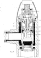
- In der Zeichnung sind zwei Ausführungsbeispiele des erfindungsgemäßen Druckspülers dargestellt, und zwar zeigen jeweils im vertikalen Mittelschnitt
- Figur 1 ein erstes Ausführungsbeispiel in der geschlossenen Ruhestellung,
- Figur 2 das Ausführungsbeispiel der Figur 1 zu Beginn eines Spülvorganges,
- Figur 3 ein zweites Ausführungsbeispiel in der Stellung zu Beginn eines Spülvorganges mit großer Spülmenge,
- Figur 4 das Ausführungsbeispiel der Figur 3 in der Stellung zu Beginn eines Spülvorganges mit kleiner Spülmenge.
- Der Druckspüler der Figuren 1 und 2 enthält in seinem Gehäuse 1 einen Spülventilkolben 2, der mittels einer Feder 3 auf einen Absperrsitz 4 im Gehäuse 1 gedrückt wird Der im Gehäuseeintritt 5 herrschende, in Öffnungsrichtung auf den Spülventilkolben 2 einwirkende Wasserdruck wird durch den in der Schließrichtung aufgebauten und einwirkenden Wasserdruck in einer Druckausgleichskammer 6 kompensiert, die durch eine im Spülventilkolben 2 ausgebildete Zulaufdüse 7 mit dem Gehäuseeintritt 5 verbunden ist. Durch Öffnen eines Entlastungsventils 8 mittels einer Druckspülertaste 9 kann Wasser aus der Druckausgleichskammer 6 in einen zum Wasseraustrittsende des Gehäuses führenden Ablaufkanal 10 abfließen und tritt in der Druckausgleichskammer eine Druckentlastung ein, so daß der Spülventilkolben 2 durch den am Gehäuseeintritt 5 herrschenden Wasserdruck gegen die Kraft der Feder 3 in die Öffnungsstellung angehoben werden kann. Durch Schließen des Entlastungsventils setzt wieder durch die Zulaufdüse 7 ein Druckaufbau in der Druckausgleichskammer 6 ein und wird dadurch der Schließvorgang des Spülventilkolbens 2 unter Mitwirkung der Feder 3 eingeleitet.
- Das Entlastungsventil ist mit einer Entlastungsdüse 11 ausgebildet, die auch bei vollständiger Öffnung des Entlastungsventils den Wasseraustritt von der Druckausgleichskammer 6 in den Ablaufkanal 10 drosselt und verzögert und deren Drosselquerschnitt um einen vorbestimmten kleinen Betrag größer ist als der Drosselquerschnitt der Zulaufdüse 7. Da hierdurch die Entlastungsdüse 11 bei geöffnetem Entlastungsventil 8 nur wenig mehr Wasser aus der Druckausgleichskammer 6 entweichen läßt als durch die Zulaufdüse 7 in die Kammer 6 nachfließen kann, entlastet sich die Kammer 6 verzögert und verlangsamt, wird dadurch der Spülventilkolben 2 langsamer vom Absperrsitz 4 angehoben als es bisher bei den bekannten Druckspülern der Fall war, und setzt infolgedessen der Spülvorgang allmählicher, langsamer an Intensität zunehmend, ein.
- An der Druckspülertaste 9 greift eine Rückstellfeder 12 an, gegen deren Rückstellkraft die Taste 9 zum Öffnen des Entlastungsventils herunterdrückbar ist. Das Entlastungsventil 8 weist einen Verschlußstößel 13 auf, der nicht mit der Druckspülertaste 9 in einteiliger Art zusammenhängt oder verbunden ist, sondern von der Taste 9 abgetrennt ist. Es genügt ein Betätigungsimpuls auf die Druckspülertaste 9, um durch einen Berührungsstoß der Taste 9 den Verschlußstößel 13 vom Verschlußsitz 14 des Entlastungsventils nach unten abzudrücken. Von diesem Moment an setzt die Druckentlastung in der Kammer 6 ein und kann der Verschlußstößel 13 selbsttätig, frei fallend bis auf einen Mitnehmeranschlag 15 des Spülventilkolbens 2 absinken. Der infolge der Druckentlastung der Kammer 6 hochsteigende Spülventilkolben 2 nimmt während seines Öffnungsvorganges den Verschlußstößel 13 mit. Sobald der Spülventilkolben 2 gegen Ende seines Öffnungsvorganges den Verschlußstößel 13 an den Verschlußsitz 14 angedrückt hat und das Entlastungsventil 8 geschlossen ist, setzt der Schließvorgang des Spülventilkolbens 2 ein. Durch die Öffnungsgeschwindigkeit des Spülventilkolbens 2, die von der Querschnittsdifferenz der beiden Düsenbohrungen 11 und 7 abhängt, durch die Schließgeschwindigkeit des Kolbens 2, die von der Größe der Düsenbohrung 7 allein abhängt, und durch das Maß, um das der Verschlußstößel 13 vom Anliegen am Verschlußsitz 14 bis zum Aufsetzen auf den Mitnehmeranschlag 15 absinken kann, wird unabhängig von der Handbetätigung der Druckspülertaste 9 selbsttätig eine vorbestimmte und gleichbleibende Spülzeit und Spülmenge eingehalten.
- Bei dem Druckspüler der Figuren 3 und 4 ist derjenige Teil des Entlastungsventils 8, der den Verschlußsitz 14 für den Verschlußstößel 13 enthält, nicht wie beim Ausführungsbeispiel der Figuren 1 und 2 ein ortsfester Teil des Druckspülergehäuses, sondern ein Kolbenkörper 16, der im Druckspülergehäuse abgedichtet und gleichachsig zum Verschlußstößel 13 verschiebbar ist. Wird die Druckspülertaste 9 nur leicht gedrückt, stößt die Taste 9 nur gegen das obere Ende des Verschlußstößels 13 an und wird, wie in Figur 3 gezeigt, nur der Verschlußstößel 13 vom Verschlußsitz 14 zum Öffnen des Entlastungsventils 8 abgedrückt, womit analog wie zu dem Ausführungsbeispiel der Figuren 1 und 2 beschrieben ein Spülvorgang mit großer Spülmenge erfolgt. Wird hingegen die Druckspülertaste 9 bewußt und absichtlich fester und tiefer gedrückt, stößt die Taste nach dem Abdrücken des Verschlußstößels 13 vom Verschlußsitz 14 auch gegen das obere Ende des Kolbenkörpers 16 und wird, wie in Figur 4 gezeigt, der Kolbenkörper mittels der Taste 9 heruntergeschoben, wobei die Herunterschiebbarkeit durch eine Hubbegrenzung 17 begrenzt ist. Hierdurch wird das Maß, um das sich der Verschlußstößel 13 von dem Verschlußsitz 14 bis zum Mitnehmeranschlag 15 des Spülventilkolbens absenkt, kleiner als im Falle der Figur 3, so daß der Spülventilkolben insgesamt weniger Weg und weniger Zeit braucht, um den Verschlußstößel 13 gegen den heruntergeschobenen Verschlußsitz 14 anzudrücken und danach sich auf den eigenen Absperrsitz 4 abzusenken. Während der Öffnungs- und Schließphase des Spülventilkolbens 2 fließt also nur eine geringere Spülmenge durch den Druckspüler als im Falle der Figur 3. Die Spülmenge hat den vorbestimmten, zulässig kleinsten Betrag, wenn der Kolbenkörper 16 durch gewollt festes Drücken der Taste 9 bis auf die Hubbegrenzung 17 heruntergeschoben wird. Durch den Druckaufbau in der Druckausgleichskammer 6 nach dem Schließen des Entlastungsventils, durch den der Spülventilkolben 2 in die Schließstellung heruntergeschoben wird, wird auch der Kolbenkörper 16 wieder in die Ausgangsstellung hochgeschoben.
Claims (2)
Priority Applications (1)
| Application Number | Priority Date | Filing Date | Title |
|---|---|---|---|
| AT87113747T ATE49435T1 (de) | 1986-10-14 | 1987-09-19 | Druckspueler fuer wasserklosetts. |
Applications Claiming Priority (2)
| Application Number | Priority Date | Filing Date | Title |
|---|---|---|---|
| DE19863634954 DE3634954A1 (de) | 1986-10-14 | 1986-10-14 | Druckspueler fuer wasserklosetts |
| DE3634954 | 1986-10-14 |
Publications (3)
| Publication Number | Publication Date |
|---|---|
| EP0264638A2 true EP0264638A2 (de) | 1988-04-27 |
| EP0264638A3 EP0264638A3 (en) | 1988-10-05 |
| EP0264638B1 EP0264638B1 (de) | 1990-01-10 |
Family
ID=6311697
Family Applications (1)
| Application Number | Title | Priority Date | Filing Date |
|---|---|---|---|
| EP87113747A Expired - Lifetime EP0264638B1 (de) | 1986-10-14 | 1987-09-19 | Druckspüler für Wasserklosetts |
Country Status (5)
| Country | Link |
|---|---|
| EP (1) | EP0264638B1 (de) |
| AT (1) | ATE49435T1 (de) |
| DE (2) | DE3634954A1 (de) |
| ES (1) | ES2012380B3 (de) |
| GR (1) | GR3000421T3 (de) |
Cited By (11)
| Publication number | Priority date | Publication date | Assignee | Title |
|---|---|---|---|---|
| DE3834328A1 (de) * | 1988-10-08 | 1990-04-12 | Benkiser Werk Gmbh & Co Kg | Klosettdruckspueler |
| WO1993016240A1 (en) * | 1992-02-07 | 1993-08-19 | S.A. & J.E. Hill Pty.Ltd. | Mains pressure flusher valve |
| US5725197A (en) * | 1992-02-07 | 1998-03-10 | Dianna Adele Hill | Mains pressure flusher valve |
| FR2913085A1 (fr) | 2007-02-27 | 2008-08-29 | Delabie Sa | Robinet temporise a declenchement souple. |
| FR2935036A1 (fr) * | 2008-08-12 | 2010-02-19 | Delabie | Robinet a declenchement souple et a double temporisation pour fluide |
| WO2011155907A1 (fr) | 2010-06-10 | 2011-12-15 | Societe De Production D'articles En Laiton "Sopal" | Dispositif de fermeture automatique temporisée |
| EP2238375A4 (de) * | 2008-01-02 | 2013-05-22 | Microflow Int Pty Ltd | Zeitgesteuertes strömungsventil |
| CN104294897A (zh) * | 2013-07-16 | 2015-01-21 | 李飞宇 | 一种用水压控制提升的开启装置及冲洗装置 |
| CN109296796A (zh) * | 2018-12-13 | 2019-02-01 | 任泊向 | 一种机械式延时装置 |
| CN112302122A (zh) * | 2020-10-22 | 2021-02-02 | 厦门建霖健康家居股份有限公司 | 一种冲水装置 |
| EP3832180A1 (de) * | 2019-12-06 | 2021-06-09 | Delabie | Automatischer zeitverzögerter schliessmechanismus für ein ventil |
Family Cites Families (7)
| Publication number | Priority date | Publication date | Assignee | Title |
|---|---|---|---|---|
| DE567158C (de) * | 1930-11-25 | 1932-12-29 | Benkiser Werk Akt Ges | Spuelventil |
| US2689706A (en) * | 1950-08-23 | 1954-09-21 | Carlson Carl Oscar | Pilot controlled flush valve |
| US2872150A (en) * | 1956-10-15 | 1959-02-03 | Imp Brass Mfg Co | Flushing valve |
| DE1206816B (de) * | 1960-05-16 | 1965-12-09 | Werner Boehler Fa | Klosettdruckspueler |
| US3674237A (en) * | 1970-10-28 | 1972-07-04 | William T Heyer | Flush valve |
| US4268008A (en) * | 1979-10-22 | 1981-05-19 | Bradley Corporation | Push button faucet |
| DE3275570D1 (en) * | 1982-11-15 | 1987-04-09 | Rene Blanc | Semi-automatic valve for the discharge of a predetermined volume of fluid under pressure, particularly a flush valve |
-
1986
- 1986-10-14 DE DE19863634954 patent/DE3634954A1/de active Granted
-
1987
- 1987-09-19 AT AT87113747T patent/ATE49435T1/de not_active IP Right Cessation
- 1987-09-19 EP EP87113747A patent/EP0264638B1/de not_active Expired - Lifetime
- 1987-09-19 DE DE8787113747T patent/DE3761386D1/de not_active Expired - Fee Related
- 1987-09-19 ES ES87113747T patent/ES2012380B3/es not_active Expired - Lifetime
-
1990
- 1990-04-04 GR GR90400202T patent/GR3000421T3/el unknown
Cited By (16)
| Publication number | Priority date | Publication date | Assignee | Title |
|---|---|---|---|---|
| DE3834328A1 (de) * | 1988-10-08 | 1990-04-12 | Benkiser Werk Gmbh & Co Kg | Klosettdruckspueler |
| WO1993016240A1 (en) * | 1992-02-07 | 1993-08-19 | S.A. & J.E. Hill Pty.Ltd. | Mains pressure flusher valve |
| US5725197A (en) * | 1992-02-07 | 1998-03-10 | Dianna Adele Hill | Mains pressure flusher valve |
| FR2913085A1 (fr) | 2007-02-27 | 2008-08-29 | Delabie Sa | Robinet temporise a declenchement souple. |
| EP1965111A1 (de) | 2007-02-27 | 2008-09-03 | Delabie | Selbstschlussarmatur |
| EP2238375A4 (de) * | 2008-01-02 | 2013-05-22 | Microflow Int Pty Ltd | Zeitgesteuertes strömungsventil |
| EP2157250A1 (de) | 2008-08-12 | 2010-02-24 | Delabie | Flexibler Auslösehahn mit zweifacher Zeitverzögerung für Flüssigkeit |
| FR2935036A1 (fr) * | 2008-08-12 | 2010-02-19 | Delabie | Robinet a declenchement souple et a double temporisation pour fluide |
| WO2011155907A1 (fr) | 2010-06-10 | 2011-12-15 | Societe De Production D'articles En Laiton "Sopal" | Dispositif de fermeture automatique temporisée |
| CN104294897A (zh) * | 2013-07-16 | 2015-01-21 | 李飞宇 | 一种用水压控制提升的开启装置及冲洗装置 |
| CN109296796A (zh) * | 2018-12-13 | 2019-02-01 | 任泊向 | 一种机械式延时装置 |
| CN109296796B (zh) * | 2018-12-13 | 2023-12-08 | 任泊向 | 一种机械式延时装置 |
| EP3832180A1 (de) * | 2019-12-06 | 2021-06-09 | Delabie | Automatischer zeitverzögerter schliessmechanismus für ein ventil |
| FR3104227A1 (fr) * | 2019-12-06 | 2021-06-11 | Delabie | Mécanisme à fermeture automatique temporisée pour un robinet, tel qu’un robinet pour douche, lavabo ou urinoir, et robinet le comprenant |
| CN112302122A (zh) * | 2020-10-22 | 2021-02-02 | 厦门建霖健康家居股份有限公司 | 一种冲水装置 |
| CN112302122B (zh) * | 2020-10-22 | 2025-11-21 | 厦门建霖健康家居股份有限公司 | 一种冲水装置 |
Also Published As
| Publication number | Publication date |
|---|---|
| DE3761386D1 (de) | 1990-02-15 |
| GR3000421T3 (en) | 1991-06-28 |
| DE3634954C2 (de) | 1989-08-31 |
| DE3634954A1 (de) | 1988-04-28 |
| EP0264638B1 (de) | 1990-01-10 |
| ATE49435T1 (de) | 1990-01-15 |
| ES2012380B3 (es) | 1990-03-16 |
| EP0264638A3 (en) | 1988-10-05 |
Similar Documents
| Publication | Publication Date | Title |
|---|---|---|
| EP2865817B1 (de) | Ablaufgarnitur für einen Spülkasten | |
| DE2660453C2 (de) | ||
| EP0264638B1 (de) | Druckspüler für Wasserklosetts | |
| DE2340449A1 (de) | Hydraulischer spueltank mit einer verbesserten aufsetz- und wiederabdichteinrichtung | |
| DE2933183T1 (de) | A liquid dispensing device | |
| EP0103045A1 (de) | Spülkasten-Ablaufventil | |
| EP0312750A2 (de) | Druckspüler für Wasserklosetts | |
| DE69717222T2 (de) | Schwimmerventil | |
| DE60111229T2 (de) | Zweimengenspülventil | |
| DE19501355A1 (de) | Ablaufarmatur eines Spülkastens | |
| DE69223645T2 (de) | Flüssigkeitsdurchflussventil | |
| DE10002308C2 (de) | WC-Spülkasten | |
| DE2320591C2 (de) | Mehrwegeventil für Zentralheizungskreise, mit RückfluBsicherung | |
| DE8627410U1 (de) | Druckspüler für Wasserklosetts | |
| EP1537277B1 (de) | Spülvorrichtung mit einer unter druck stehenden kammer, ablaufarmatur für eine spülvorrichtung sowie anlage mit einer spülvorrichtung und einer toilettenschüssel | |
| DE2745505A1 (de) | Wasserspuelkasten fuer toiletten | |
| DE551976C (de) | Spuelventil mit einem Haupt- und Hilfsventil | |
| DE3123501A1 (de) | System zur funktionserweiterung konventioneller wc-spuelkaesten | |
| DE3140033A1 (de) | System zur funktionserweiterung konventioneller wc-spuelkaesten | |
| DE69105268T2 (de) | Druckknopfspülmechanismus mit eintauchbarem Körper. | |
| DE2347524B2 (de) | Selbsttaetig schliessendes mischventil mit einem mit zwei seitlichen wassereintrittsoeffnungen versehenen gehaeuse | |
| DE3001826C2 (de) | Vorrichtung zur Spülung einer Klosettmuschel | |
| EP0859093B1 (de) | Ablaufvorrichtung an einem WC-Spülkasten mit wahlweiser Voll- oder Teilspülung | |
| DE963319C (de) | Spuelkasten, insbesondere fuer Klosettanlagen | |
| DE3738270C2 (de) |
Legal Events
| Date | Code | Title | Description |
|---|---|---|---|
| PUAI | Public reference made under article 153(3) epc to a published international application that has entered the european phase |
Free format text: ORIGINAL CODE: 0009012 |
|
| AK | Designated contracting states |
Kind code of ref document: A2 Designated state(s): AT BE CH DE ES FR GB GR IT LI LU NL SE |
|
| PUAL | Search report despatched |
Free format text: ORIGINAL CODE: 0009013 |
|
| AK | Designated contracting states |
Kind code of ref document: A3 Designated state(s): AT BE CH DE ES FR GB GR IT LI LU NL SE |
|
| 17P | Request for examination filed |
Effective date: 19881021 |
|
| 17Q | First examination report despatched |
Effective date: 19890614 |
|
| GRAA | (expected) grant |
Free format text: ORIGINAL CODE: 0009210 |
|
| AK | Designated contracting states |
Kind code of ref document: B1 Designated state(s): AT BE CH DE ES FR GB GR IT LI LU NL SE |
|
| PG25 | Lapsed in a contracting state [announced via postgrant information from national office to epo] |
Ref country code: SE Effective date: 19900110 Ref country code: NL Effective date: 19900110 Ref country code: GB Effective date: 19900110 |
|
| REF | Corresponds to: |
Ref document number: 49435 Country of ref document: AT Date of ref document: 19900115 Kind code of ref document: T |
|
| ET | Fr: translation filed | ||
| REF | Corresponds to: |
Ref document number: 3761386 Country of ref document: DE Date of ref document: 19900215 |
|
| ITF | It: translation for a ep patent filed | ||
| NLV1 | Nl: lapsed or annulled due to failure to fulfill the requirements of art. 29p and 29m of the patents act | ||
| GBV | Gb: ep patent (uk) treated as always having been void in accordance with gb section 77(7)/1977 [no translation filed] | ||
| REG | Reference to a national code |
Ref country code: GR Ref legal event code: FG4A Free format text: 3000421 |
|
| PLBE | No opposition filed within time limit |
Free format text: ORIGINAL CODE: 0009261 |
|
| STAA | Information on the status of an ep patent application or granted ep patent |
Free format text: STATUS: NO OPPOSITION FILED WITHIN TIME LIMIT |
|
| 26N | No opposition filed | ||
| ITTA | It: last paid annual fee | ||
| EPTA | Lu: last paid annual fee | ||
| PGFP | Annual fee paid to national office [announced via postgrant information from national office to epo] |
Ref country code: FR Payment date: 19940829 Year of fee payment: 8 |
|
| PGFP | Annual fee paid to national office [announced via postgrant information from national office to epo] |
Ref country code: GR Payment date: 19940831 Year of fee payment: 8 |
|
| PGFP | Annual fee paid to national office [announced via postgrant information from national office to epo] |
Ref country code: LU Payment date: 19940901 Year of fee payment: 8 |
|
| PGFP | Annual fee paid to national office [announced via postgrant information from national office to epo] |
Ref country code: ES Payment date: 19940905 Year of fee payment: 8 |
|
| PGFP | Annual fee paid to national office [announced via postgrant information from national office to epo] |
Ref country code: BE Payment date: 19940914 Year of fee payment: 8 Ref country code: AT Payment date: 19940914 Year of fee payment: 8 |
|
| PGFP | Annual fee paid to national office [announced via postgrant information from national office to epo] |
Ref country code: CH Payment date: 19940916 Year of fee payment: 8 |
|
| PGFP | Annual fee paid to national office [announced via postgrant information from national office to epo] |
Ref country code: DE Payment date: 19941021 Year of fee payment: 8 |
|
| PG25 | Lapsed in a contracting state [announced via postgrant information from national office to epo] |
Ref country code: LU Free format text: LAPSE BECAUSE OF NON-PAYMENT OF DUE FEES Effective date: 19950919 Ref country code: AT Effective date: 19950919 |
|
| PG25 | Lapsed in a contracting state [announced via postgrant information from national office to epo] |
Ref country code: ES Free format text: LAPSE BECAUSE OF EXPIRATION OF PROTECTION Effective date: 19950920 |
|
| PG25 | Lapsed in a contracting state [announced via postgrant information from national office to epo] |
Ref country code: LI Effective date: 19950930 Ref country code: CH Effective date: 19950930 Ref country code: BE Effective date: 19950930 |
|
| BERE | Be: lapsed |
Owner name: METALLWERKE GEBR. SEPPELFRICKE G.M.B.H. & CO. Effective date: 19950930 |
|
| PG25 | Lapsed in a contracting state [announced via postgrant information from national office to epo] |
Ref country code: GR Free format text: THE PATENT HAS BEEN ANNULLED BY A DECISION OF A NATIONAL AUTHORITY Effective date: 19960331 |
|
| REG | Reference to a national code |
Ref country code: CH Ref legal event code: PL |
|
| PG25 | Lapsed in a contracting state [announced via postgrant information from national office to epo] |
Ref country code: FR Effective date: 19960531 |
|
| REG | Reference to a national code |
Ref country code: GR Ref legal event code: MM2A Free format text: 3000421 |
|
| PG25 | Lapsed in a contracting state [announced via postgrant information from national office to epo] |
Ref country code: DE Effective date: 19960601 |
|
| REG | Reference to a national code |
Ref country code: FR Ref legal event code: ST |
|
| REG | Reference to a national code |
Ref country code: ES Ref legal event code: FD2A Effective date: 19990601 |
|
| PG25 | Lapsed in a contracting state [announced via postgrant information from national office to epo] |
Ref country code: IT Free format text: LAPSE BECAUSE OF NON-PAYMENT OF DUE FEES;WARNING: LAPSES OF ITALIAN PATENTS WITH EFFECTIVE DATE BEFORE 2007 MAY HAVE OCCURRED AT ANY TIME BEFORE 2007. THE CORRECT EFFECTIVE DATE MAY BE DIFFERENT FROM THE ONE RECORDED. Effective date: 20050919 |