EP0264644A2 - Montage pour simuler le contact NSI par le circuit de maintien dans un appareil téléphonique à deux chemins - Google Patents
Montage pour simuler le contact NSI par le circuit de maintien dans un appareil téléphonique à deux chemins Download PDFInfo
- Publication number
- EP0264644A2 EP0264644A2 EP87113787A EP87113787A EP0264644A2 EP 0264644 A2 EP0264644 A2 EP 0264644A2 EP 87113787 A EP87113787 A EP 87113787A EP 87113787 A EP87113787 A EP 87113787A EP 0264644 A2 EP0264644 A2 EP 0264644A2
- Authority
- EP
- European Patent Office
- Prior art keywords
- circuit
- subscriber line
- hold circuit
- switched
- arrangement
- Prior art date
- Legal status (The legal status is an assumption and is not a legal conclusion. Google has not performed a legal analysis and makes no representation as to the accuracy of the status listed.)
- Withdrawn
Links
Images
Classifications
-
- H—ELECTRICITY
- H04—ELECTRIC COMMUNICATION TECHNIQUE
- H04M—TELEPHONIC COMMUNICATION
- H04M3/00—Automatic or semi-automatic exchanges
- H04M3/42—Systems providing special services or facilities to subscribers
- H04M3/58—Arrangements for transferring received calls from one subscriber to another; Arrangements affording interim conversations between either the calling or the called party and a third party
-
- H—ELECTRICITY
- H04—ELECTRIC COMMUNICATION TECHNIQUE
- H04M—TELEPHONIC COMMUNICATION
- H04M1/00—Substation equipment, e.g. for use by subscribers
- H04M1/26—Devices for calling a subscriber
- H04M1/30—Devices which can set up and transmit only one digit at a time
- H04M1/31—Devices which can set up and transmit only one digit at a time by interrupting current to generate trains of pulses; by periodically opening and closing contacts to generate trains of pulses
- H04M1/312—Devices which can set up and transmit only one digit at a time by interrupting current to generate trains of pulses; by periodically opening and closing contacts to generate trains of pulses pulses produced by electronic circuits
-
- H—ELECTRICITY
- H04—ELECTRIC COMMUNICATION TECHNIQUE
- H04M—TELEPHONIC COMMUNICATION
- H04M9/00—Arrangements for interconnection not involving centralised switching
- H04M9/002—Arrangements for interconnection not involving centralised switching with subscriber controlled access to a line, i.e. key telephone systems
Definitions
- the invention relates to a circuit arrangement for emulating the NSI contact by means of the electronic hold circuit in a two-way telephone with microprocessor control fed via the subscriber line, with a rectifier bridge per subscriber line as reverse polarity protection, with a keypad for subscriber selection and for special functions, with a speech circuit with a switching device for Choice of the subscriber line to be occupied and with an electronic hold circuit between the wires of each subscriber line, the hold circuit containing a current path which can be switched on and off via the microprocessor and consists of the series connection of a thyristor, a load resistor and a series transistor.
- the above-mentioned telephone stations are known as two-way telephones (two-way telephones, operating instructions of the Germanierepost FeTAp 2L-716-796), whereby the individual subscriber lines can be optionally switched on, for example, with the aid of lockable buttons, and the necessary between the a / b wires when asked or brokered Holding resistors can be switched on and off by contacts of the buttons or by relay contacts.
- the object of the invention is now to expand the electronic hold circuit without much effort so that it can also be used as an NSI contact during the dialing process at the telephone station, the circuit arrangement should be integrable, the voltage (high voltage) separation of the subscriber line and speech circuit and a control with controls designed only for low currents.
- the circuit arrangement is explained using a drawing.
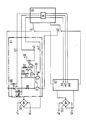
- the drawing shows a speech circuit SS with a Microprocessor M, the two holding circuits H1 and H2, the rectifier bridges Gl1 and Gl2 intended as reverse polarity protection, the two subscriber lines a1 / b1 and a2 / b2 and the two line changeover contacts l1 and l2.
- the two holding circuits H1 and H2 are of the same type.
- the holding circuit H1 shows further details such as the thyristor Ty with the holding circuit C / R1, the holding resistor or load resistor RL, the series transistor T1, the transistor optocouplers T2 and T5 and the switching transistors T3 and T4.
- the control connection points for the microprocessor are given as m1, m2 and m3 (m4, m5 and m6 for H2).
- the optically controlled thyristor Ty receives an ignition pulse via the control terminal m1, whereby it switches through and remains switched through by a holding current determined via C and R1.
- the current path for the direct current applied via the rectifier bridge Gl1 runs through the thyristor Ty, the load resistor RL and the series transistor T1. The latter is switched on because part of the holding current is tapped from Ty and acts as the base current of T1, which in turn the holding current for Ty is maintained.
- the latter goes into the blocking circuit and thus also interrupts the holding current for the thyristor Ty, which now also interrupts the current path.
- the load resistor RL from the subscriber line a1 / b1 is thus switched.
- the potential at m3 can also be switched off.
- the holding circuit H2 with the control points m4, m5 and m6 works accordingly. If this hold circuit, for example H1, is to function as an NSI contact, then it must cut or short-circuit the wires a1 / b1 of the subscriber line in time with the dialing pulses.
- a pulse is given via the control point m1 to the optically controlled transistor Ty, so that, as already described, this switches through, forms its holding current and the base current for the series transistor T1, the latter also switching through.
- the current path is now switched through.
- the load resistor RL is now bridged via the diodes D1 and D2 and the transistors T3 and T4 (arrangement of semiconductor components) since there is no potential at the control point M3.
- the transistor optocoupler thus remains in the blocking state and the holding current can result from the resistor R2 or the current through the current path form a base voltage which switches on the transistors T3 and T4.
- the two diodes D1 and D2 serve to drop a defined voltage across the resistor R2.
- the opening of the NSI contact corresponding to the selection clock is effected in that a control pulse is applied to the control point m2, whereby the transistor optocoupler switches through, which in turn derives the base current of the series transistor T1.
- the series transistor turns off. The current path is thus interrupted and the thyristor T4 is switched into the blocking state.
- the hold circuit H2 functions analogously when a subscriber is selected via the subscriber line a2 / b2.
- the voltage + UB in the figure is the respective operating voltage of the semiconductor elements Ty, T2 and T3.
Landscapes
- Engineering & Computer Science (AREA)
- Signal Processing (AREA)
- Interface Circuits In Exchanges (AREA)
Applications Claiming Priority (2)
| Application Number | Priority Date | Filing Date | Title |
|---|---|---|---|
| DE3632200 | 1986-09-23 | ||
| DE3632200 | 1986-09-23 |
Publications (2)
| Publication Number | Publication Date |
|---|---|
| EP0264644A2 true EP0264644A2 (fr) | 1988-04-27 |
| EP0264644A3 EP0264644A3 (fr) | 1989-06-14 |
Family
ID=6310099
Family Applications (1)
| Application Number | Title | Priority Date | Filing Date |
|---|---|---|---|
| EP87113787A Withdrawn EP0264644A3 (fr) | 1986-09-23 | 1987-09-21 | Montage pour simuler le contact NSI par le circuit de maintien dans un appareil téléphonique à deux chemins |
Country Status (4)
| Country | Link |
|---|---|
| EP (1) | EP0264644A3 (fr) |
| AU (1) | AU600523B2 (fr) |
| FI (1) | FI874140A7 (fr) |
| IN (1) | IN167984B (fr) |
Cited By (1)
| Publication number | Priority date | Publication date | Assignee | Title |
|---|---|---|---|---|
| ES2046112A2 (es) * | 1992-04-24 | 1994-01-16 | Revenga Ingenieros S A | Equipo telefonico para lineas directas punto a punto. |
Families Citing this family (1)
| Publication number | Priority date | Publication date | Assignee | Title |
|---|---|---|---|---|
| IN164858B (fr) * | 1986-09-11 | 1989-06-17 | Siemens Ag |
Family Cites Families (4)
| Publication number | Priority date | Publication date | Assignee | Title |
|---|---|---|---|---|
| NL7907134A (nl) * | 1979-09-25 | 1981-03-27 | Ericsson Telefon Mij | Telefooninstallatie van de als sterpuntinstallatie aangeduide soort. |
| AT377606B (de) * | 1981-08-07 | 1985-04-10 | Dynamit Nobel Ag | Sprengmomentzuender |
| US4490583A (en) * | 1983-02-14 | 1984-12-25 | Circom, Inc. | Plural line telephone controller |
| IN164858B (fr) * | 1986-09-11 | 1989-06-17 | Siemens Ag |
-
1987
- 1987-08-03 IN IN599/CAL/87A patent/IN167984B/en unknown
- 1987-09-21 EP EP87113787A patent/EP0264644A3/fr not_active Withdrawn
- 1987-09-22 FI FI874140A patent/FI874140A7/fi not_active IP Right Cessation
- 1987-09-22 AU AU78835/87A patent/AU600523B2/en not_active Ceased
Cited By (1)
| Publication number | Priority date | Publication date | Assignee | Title |
|---|---|---|---|---|
| ES2046112A2 (es) * | 1992-04-24 | 1994-01-16 | Revenga Ingenieros S A | Equipo telefonico para lineas directas punto a punto. |
Also Published As
| Publication number | Publication date |
|---|---|
| AU7883587A (en) | 1988-03-31 |
| FI874140A0 (fi) | 1987-09-22 |
| EP0264644A3 (fr) | 1989-06-14 |
| FI874140A7 (fi) | 1988-03-24 |
| IN167984B (fr) | 1991-01-19 |
| AU600523B2 (en) | 1990-08-16 |
Similar Documents
| Publication | Publication Date | Title |
|---|---|---|
| DE3423682C2 (fr) | ||
| EP0264644A2 (fr) | Montage pour simuler le contact NSI par le circuit de maintien dans un appareil téléphonique à deux chemins | |
| DE2522957A1 (de) | Schaltungsanordnung fuer ueber ihre anschlussleitungen gespeiste teilnehmerstationen mit impulstastwahl in fernmelde-, insbesondere fernsprechanlagen | |
| DE2809905A1 (de) | Relais-halteschaltung | |
| EP0328743B1 (fr) | Installation de commande pour mise en marche sélective de différents appareils électriques, spécialement d'autoradios dans un but de démonstration | |
| EP0263972A2 (fr) | Circuit de maintien électronique pour appareil téléphonique à deux chemins alimenté par la ligne d'abonné | |
| DE3641763C2 (fr) | ||
| DE2434321C3 (de) | Schaltungsanordnung für tastengesteuerte Wechselsprech-, Gegensprech- oder Lautsprecheranlagen | |
| DE3705816C2 (fr) | ||
| DE2437038C3 (de) | Schaltungsanordnung für Fernsprechapparate mit unechter Tastenwahl | |
| EP0286793B1 (fr) | Circuit pour la protection contre des surtensions et pour l'injection du courant de sonnerie dans la ligne de connexion pour centraux de télécommunication spécialement pour les centraux téléphoniques | |
| DE3833745C2 (fr) | ||
| DE879255C (de) | Schaltungsanordnung in Fernmeldeanlagen mit Waehlerbetrieb, insbesondere Fernsprechnebenstellenanlagen | |
| DE2541769A1 (de) | Schaltungsanordnung fuer ein fernschaltgeraet | |
| DE3937181A1 (de) | Wechselschaltvorrichtung fuer eine fernsprecheinrichtung zum anschluss zweier sprechstellen an eine gemeinsame fernsprechleitung | |
| DE4109845A1 (de) | Wechselschaltvorrichtung fuer eine fernsprecheinrichtung zum anschluss zweier sprechstellen an eine gemeinsame fernsprechleitung | |
| DE677049C (de) | Schaltungsanordnung fuer Fernsprechanlagen mit Waehlerbetrieb und Gesellschaftsleitungen | |
| DE2536201A1 (de) | Schaltungsanordnung zur abgabe von waehlimpulsen mit einem transistor, insbesondere fuer fernsprechapparate | |
| DE3824633C2 (fr) | ||
| DE2415451C2 (de) | Schaltungsanordnung für kleine Fernsprechnebenstellenanlagen mit einer Haupt- und einer Nebenstelle | |
| DE2816347C3 (de) | Schaltungsanordnung für über Anschlußleitungen gespeiste Teilnehmerstationen mit Wähleinrichtungen in Fernmelde-, insbesondere Fernsprechanlagen | |
| DE874159C (de) | Schaltungsanordnung fuer Fernsprechanlagen mit Waehlerbetrieb und Zweieranschluessen | |
| DE2618496B2 (de) | Schaltungsanordnung für Zielwahleinrichtung in Fernmelde-, insbesondere Fernsprechanlagen | |
| DE1166839B (de) | Schaltungsanordnung fuer Zweieranschluesse | |
| DE1512053B2 (fr) |
Legal Events
| Date | Code | Title | Description |
|---|---|---|---|
| PUAI | Public reference made under article 153(3) epc to a published international application that has entered the european phase |
Free format text: ORIGINAL CODE: 0009012 |
|
| AK | Designated contracting states |
Kind code of ref document: A2 Designated state(s): DE GB NL |
|
| PUAL | Search report despatched |
Free format text: ORIGINAL CODE: 0009013 |
|
| AK | Designated contracting states |
Kind code of ref document: A3 Designated state(s): DE GB NL |
|
| 17P | Request for examination filed |
Effective date: 19891108 |
|
| STAA | Information on the status of an ep patent application or granted ep patent |
Free format text: STATUS: THE APPLICATION HAS BEEN WITHDRAWN |
|
| 18W | Application withdrawn |
Withdrawal date: 19910612 |
|
| R18W | Application withdrawn (corrected) |
Effective date: 19910612 |
|
| RIN1 | Information on inventor provided before grant (corrected) |
Inventor name: STRZELETZ, WOLFGANG, DIPL.-ING. |