EP0264783A2 - Klappmöbel - Google Patents
Klappmöbel Download PDFInfo
- Publication number
- EP0264783A2 EP0264783A2 EP87114948A EP87114948A EP0264783A2 EP 0264783 A2 EP0264783 A2 EP 0264783A2 EP 87114948 A EP87114948 A EP 87114948A EP 87114948 A EP87114948 A EP 87114948A EP 0264783 A2 EP0264783 A2 EP 0264783A2
- Authority
- EP
- European Patent Office
- Prior art keywords
- legs
- guide groove
- folding
- runners
- folding furniture
- Prior art date
- Legal status (The legal status is an assumption and is not a legal conclusion. Google has not performed a legal analysis and makes no representation as to the accuracy of the status listed.)
- Granted
Links
Images


Classifications
-
- A—HUMAN NECESSITIES
- A47—FURNITURE; DOMESTIC ARTICLES OR APPLIANCES; COFFEE MILLS; SPICE MILLS; SUCTION CLEANERS IN GENERAL
- A47C—CHAIRS; SOFAS; BEDS
- A47C4/00—Foldable, collapsible or dismountable chairs
- A47C4/04—Folding chairs with inflexible seats
- A47C4/08—Folding chairs with inflexible seats having a frame made of wood or plastics
- A47C4/10—Folding chairs with inflexible seats having a frame made of wood or plastics with legs pivotably connected to seat or underframe
- A47C4/12—Folding chairs with inflexible seats having a frame made of wood or plastics with legs pivotably connected to seat or underframe of adjustable type
-
- A—HUMAN NECESSITIES
- A47—FURNITURE; DOMESTIC ARTICLES OR APPLIANCES; COFFEE MILLS; SPICE MILLS; SUCTION CLEANERS IN GENERAL
- A47C—CHAIRS; SOFAS; BEDS
- A47C3/00—Chairs characterised by structural features; Chairs or stools with rotatable or vertically-adjustable seats
- A47C3/02—Rocking chairs
- A47C3/029—Rocking chairs with curved rocking members resting on the floor
Definitions
- the invention relates to folding furniture according to the preamble of patent claim 1.
- the invention relates to folding furniture as a whole, preferably to folding furniture with an adjustable backrest and / or seat, as described in particular in patent application P 36 07 619.
- the invention has for its object to provide a folding furniture of the type mentioned, which can be converted into a rocking chair and can also be folded in this function in a confined space.
- the invention creates a folding piece of furniture, in particular a folding chair, which can be used as a rocking chair or armchair by attaching runners and in doing so maintains the possibility originally given to it of adjusting the inclination of the seat surface and / or backrest angle, and at the same time in one form when not in use can be folded with the runners, which due to their compactness requires the least space for accommodation.
- the runners can be easily assembled and disassembled.
- At least one of the cross struts to be provided between the two runners can be used in different positions and thus increases comfort depending on the size of the person using the chair or armchair. It is particularly advantageous that, as a result of the special design of the runners, the armchair can be moved into the completely folded state with the runners attached and from the folded state into the fully unfolded state with little effort and with the least force.
- Fig. 1 shows in side view as folding furniture a folding armchair, as described in patent application P 36 07 619 or in patent application P 36 07 581, which has runners according to the invention attached to the lower ends of the legs.
- the folding armchair consists, as usual, of a seat 1, backrest 2, armrests 3, front legs 4, rear legs 5, and a cross strut 6 provided between the front legs 4 and a cross strut 7 arranged between the rear legs 5
- Their inclination is adjustable in that a guide and locking mechanism 12 is provided in the area of a connecting device 10, which is preferably arranged laterally between the seat surface 1 and the backrest 2, which enables the seat surface 1, which can be pivoted about an axis of rotation indicated by 13, to be inclined at different angles can be adjusted.
- a lateral pin 15 protrudes from the connecting device 10 into a guide groove 16 with different locking grooves 17a, 17b and, by adjusting the pin 15 into the different locking grooves, causes a change in the inclination of the seat surface 1.
- this is in the patent application P 36 07 619.
- the armrest 3 can be adjustable to adjust the inclination of the backrest 2, as is also specified in patent application P 36 07 619.
- Such a folding armchair can be folded into a very compact form for storage.
- the folding armchair described with reference to FIG. 1 can be converted into a rocking armchair by attaching runners 20 to the lower sections of its legs 4, 5.
- the runners 20 have an essentially curved course and are preferably designed to run straight at their end sections designated 22a, 22b with respect to the downward-facing support surface, which has the consequence that when the rocking chair is used, it tilts over when these support surfaces run straight 22a, 22b is prevented. Between the areas 22a, 22b, the contact surface of each runner 20 is curved in an arcuate or elliptical manner.
- the runners 20 are each attached laterally from the outside to the lower ends of the legs 4, 5.
- the two runners 20 can be easily and quickly assembled or disassembled from the legs 4, 5 by connecting elements to be described.
- the ends of the rear legs 5 are rotatably attached to the end area of one runner 20, while the lower ends of the front legs 4 are adjustable relative to the runner 20.
- a guide element 24 is provided at the lower end of the two front legs 4, which protrudes laterally from the legs 4 and protrudes into a guide groove 26 which extends over the predominant length of the runner 20 and in the inner surface of each runner 20.
- the runners 20 can be attached to the inner surfaces of the legs 4, 5; in this case, each guide groove 26 is located on the outward-facing surface of each runner 20 and the guide element 24 in this case protrudes laterally inwards away from the inner surface of each front leg 4.
- the guide groove 26 has an arcuate course such that this arcuate course corresponds to the path of movement of the guide element 24, which it is when folding the folding chair due to the movement of the two pairs of legs 4, 5 towards each other up to the position shown in Fig. 3 in relation to the rear leg 5 drives through.
- the guide groove 26 extends so far in the direction of the area 22a that any adjustment of the folding chair and the adjustment of the seat 1, which may result in a spreading of the associated pairs of legs 4, 5 against one another, is possible with the runners 20 attached.
- each guide groove 26 has an approximately slot-shaped opening 28 to the contact edge of each runner 20, designated 30 in FIG. 1.
- This slot-shaped opening 28 preferably has a conically widening shape from the guide groove 26 in the direction of the bearing surface 30.
- the slot-shaped opening 28 lies in the plane of the groove 26 and extends laterally away from it at one end of the groove 26.
- cross struts 32, 34 can be used between the pairs of runners according to FIG. 2, the pairs of runners being designated 20 ⁇ and 20 ⁇ in FIG. 2.
- the folding of the folding armchair is carried out in such a way that the folding armchair is adjusted from the position shown in FIG. 1 by pivoting the seat surface 1 in the direction of the backrest 2. Since the seat 1 in the embodiment shown is rotatably mounted on the front legs 4 in the region of the axis of rotation 13 and at the same time the armrest 3 in the embodiment shown is rotatably mounted on the side of the backrest 2 at 36, the respective front legs and rear legs 4, 5 also an only indicated connecting link 38 are connected to each other, causes the folding of the seat 1 on the backrest 2, or vice versa, that the pair of front legs 4 and the pair of rear legs 5 are brought into a substantially parallel position and in contact with one another, so that the state shown in Fig. 3 is reached.
- the guide elements 24 attached to the lower ends of the front legs 4 move backward within the guide groove 26, ie in the direction of the opening 28, and reach the position within the slot 28 indicated by the dashed line in FIG Reaching the parallel position of the front and rear pairs of legs as shown in Fig. 3.
- Folding the folding chair also causes the pair of runners opposite an axis of rotation 40 of the rear legs 5 performs a pivoting movement such that the angle between the rear pair of legs 5 and the pair of runners 20 becomes smaller and smaller and the runners 20 move about the axis of rotation 40 into the position shown in FIG. 3 before the guide pin 24 by completely collapsing and the movement of the legs 5, 6 in the parallel position shown in FIG. 3 emerges from the opening 28.
- the runners 20 come to lie almost in the plane of the front and rear pairs of legs 4, 5 and, in the case of the preferred folding armchair shown in connection with FIGS. 1 and 3, are in their front region in alignment with the lower surface of the armrest 3
- an extremely compact shape is guaranteed, including the articulated runners, which ensures space-saving accommodation of the folded folding armchair or rocking armchair.
- the lower ends of the rear legs 5 are rotatable in the region of the axis of rotation denoted by 40 and are fixedly connected to the runners 20 by connecting elements 42, while the front legs 4 are guided so as to be adjustable in the longitudinal direction of the runners 20.
- the arrangement can also be reversed, i.e. that the runners 20 are rotatably mounted on the lower ends of the front legs 4, while the lower ends of the rear legs 5 are guided along the runners.
- the runners rest on the contact surface of the armrests 3.
- FIG. 3 in connection with FIG. 1 is preferred, since in this embodiment an extremely compact shape can be achieved in the folded state.
- the front cross strut 32 can be provided at different distances from the front end of the pair of runners, as by the reference number chen 32 ⁇ is indicated.
- the cross strut 32 can be provided at the point 32, ie far at the front end of the pair of runners 20, if this cross strut is to serve as a footrest or for supporting the feet. If the cross strut 32 is not to be used as a footrest and the front area between the footrests should be as free as possible from such a strut in order to avoid a collision with the feet of the chair user, the cross strut is used at a position as close as possible to the end of the front legs 4 provided and indicated with 32 ⁇ .
- Each cross strut 32, 34 for example, has pins 46, 48 which can be inserted into associated bores on the inner surface of the runners 20.
- screws are preferably used in order to firmly connect the cross struts 32, 34 to the runners 20.
- other types of fastening can be used for the fixed arrangement of the struts 32, 34 between the runners 20.
- the bores in the runners 20 corresponding to the item 32 in FIG. 1 are designated by 50 and the bores in the runners 20 corresponding to the item 32 ⁇ are designated by 52.
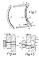
- 4a shows a sectional view along the line IVa-IVa in FIG. 1 for a preferred embodiment of the rotatable fixed mounting of the lower ends of the rear legs 5 relative to the runners 20.
- each rear leg 5 is positioned opposite the runner 20 on the inwardly facing surface of the runner 20.
- the lower end of each rear leg 5 is connected by a connecting element 54, e.g. B. in the form of a screw or knurled screw rotatably with respect to the runner 20, for which purpose the runner 20 has a sleeve 56 with an internal thread, into which the screw 54 is screwed with its threaded area.
- the the area of the connecting element 54 passing through the rear leg 5 preferably has no external thread and is provided at its end facing away from the runner 20 with a head or knurled head 57 which holds the leg 5 rotatably with respect to the runner 20 as soon as the screw 54 into the threaded sleeve 56 is screwed in. If necessary, a metal washer should be provided in the area of the screw connection 54 and between the head 57 and the inner leg 5 to reduce the frictional forces.
- each front leg 4 is slidably supported in the guide groove 26 by a connecting or guiding element 24.
- a screw bolt is provided as the connecting or guide element 24, the head 61 of which has a smaller diameter than the width of the guide groove 26 and is provided with an external thread at its end facing away from the head 61.
- the bolt 24 is passed through a hole in the lower end of the front leg 4 in question and is secured against the lower leg, for example by a nut or a knurled head 60, which is screwed onto the end of the bolt.
- the guide element 24 can thus be slidably inserted into the guide groove 26 by its head, designated 61, and is mounted within the guide groove 26 so as to be displaceable toward one another when the legs or pairs of legs 4, 5 move.
- the guide element 24 can, with its head 61, optionally perform a sliding or rolling movement with respect to the upper and lower groove walls 26a, 26b of the guide groove 26 facing it, for which purpose the head 61 is preferably cylindrical is. It can be seen that the head 61 is supported by the guide groove 26 so that it can be moved laterally out of the guide groove 26.
- the essentially U-shaped guide groove 26 does not prevent the guide element 24 from moving in the direction of an arrow A.
- the guide groove 26 can have a dovetail profile, for example, so that the underside of the head 61 slidably rests on the dovetail guide and lateral displacement of the guide element 24 out of the guide groove 26 is avoided.
- a bore corresponding to the diameter of the head 61 is to be provided at a predetermined position of the guide groove in order to allow the insertion or removal of the guide element 24.
- the invention thus creates a folding armchair that can be converted into a rocking armchair by attaching runners and still allows the possible adjustment options, such as adjusting the inclination of the backrest and / or the seat, to be carried out.
- the inventive design of the guide grooves in the two runners allows the folding armchair to be folded into an extremely compact shape when the runners are attached, the course of the guide groove being chosen such that an outwardly extending, preferably conically widening slot is provided at a predetermined position 3, for the purpose of completely collapsing into the shape shown in FIG. 3, allowing the guide element 24 to emerge from the groove 26 and thus ensuring that the end of each runner located in FIG. 3 to the axis of rotation 40 is close to the front edge of the corresponding one Armrest 3 comes to the system, which ensures the compact shape of the folding chair in the folded state.
- a folding armchair for the purpose of using the rocking runners in the area of its legs 4, 5 only has to be provided with transverse bores for carrying out the connecting elements 24 54 serve, while the runners for fastening the connecting elements 54 are provided at a predetermined point with a bore into which a threaded sleeve 56, which has, for example, an internal and external thread, can be screwed.
- the guide element denoted by 24 in FIG. 4b is designed such that the lowest possible frictional resistance occurs between the guide element 24 and the guide groove 26 and thus easy folding of the folding chair with simultaneous movement of the lower end of the front legs 4 along the guide groove 26 in the direction of the rear pair of legs 5 is reached.
- the right-hand side of the folding armchair has now been described in connection with FIGS. 1 and 3.
- the left-hand side obviously has a construction symmetrical to the middle of the armchair.
Landscapes
- Life Sciences & Earth Sciences (AREA)
- Engineering & Computer Science (AREA)
- Wood Science & Technology (AREA)
- Chairs For Special Purposes, Such As Reclining Chairs (AREA)
- Chairs Characterized By Structure (AREA)
- Special Chairs (AREA)
- Chair Legs, Seat Parts, And Backrests (AREA)
- Laminated Bodies (AREA)
- Sheet Holders (AREA)
Abstract
Description
- Die Erfindung betrifft ein Klappmöbel gemäß dem Oberbegriff des Patentanspruchs 1.
- Die Erfindung bezieht sich auf Klappmöbel insgesamt, vorzugsweise auf Klappmöbel mit verstellbarer Lehne und/oder Sitzfläche, wie sie insbesondere in der Patentanmeldung P 36 07 619 beschrieben sind.
- Der Erfindung liegt die Aufgabe zugrunde, ein Klappmöbel der eingangs genannten Art zu schaffen, welches in einen Schaukelsessel umfunktionierbar ist und auch in dieser Funktion auf engstem Raum zusammengeklappt werden kann.
- Diese Aufgabe wird erfindungsgemäß durch die Merkmale des Patentanspruchs 1 gelöst.
- Weitere Ausgestaltungen ergeben sich aus den Unteransprüchen.
- Die Erfindung schafft ein Klappmöbel, insbesondere einen Klappstuhl, der durch das Anbringen von Kufen als Schaukelstuhl bzw. -sessel verwendbar ist und hierbei die ihm ursprüngIich verliehene Möglichkeit der Verstellung der Sitzflächenneigung und/oder Rückenlehnenneigung beibehält sowie gleichzeitig im Falle des Nichtgebrauchs in eine Form zusammen mit den Kufen zusammengeklappt werden kann, die durch ihre Kompaktheit geringsten Raumbedarf zur Unterbringung erfordert. Darüber hinaus sind die Kufen auf einfachste Weise montierbar und demontierbar. Zumindest eine der zwischen den beiden Kufen vorzusehende Querstrebe läßt sich an verschiedenen Positionen einsetzen und erhöht damit abhängig von der Größe der den Stuhl bzw. Sessel verwendenden Person den Komfort. Besonders vorteilhaft ist, daß als Folge der speziellen Ausbildung der Kufen der Sessel ohne Mühe und mit geringster Kraft in den vollständig zusammengeklappten Zustand bei angesetzten Kufen und aus dem zusammengeklappten Zustand auch in den voll ausgeklappten Zustand verbracht werden kann.
- Im folgenden werden bevorzugte Ausführungsformen des Klappmöbels an Hand der Zeichnung beschrieben. Es zeigen:
- Fig. 1 eine Seitenansicht eines erfindungsgemäßen Klappmöbels mit angesetzen Kufen,
- Fig. 2 eine Perspektivdarstellung der Kufen,
- Fig. 3 eine Seitendarstellung des Klappmöbels mit angesetzten Kufen im zusammengeklappten Zustand,
- Fig. 4a und Fig. 4b Teilschnittansichten bevorzugter Ausführungsformen der Verbindungs- und Führungselemente.
- Fig. 1 zeigt in Seitenansicht als Klappmöbel einen Klappsessel, wie er in der Patentanmeldung P 36 07 619 oder in der Patentanmeldung P 36 07 581 beschrieben ist, der an den unteren Enden der Beine angesetzte erfindungsgemäße Kufen aufweist. Der Klappsessel besteht wie üblich aus einer Sitzfläche 1, Rückenlehne 2, Armlehnen 3, vorderen Beinen 4, hinteren Beinen 5, sowie einer zwischen den vorderen Beinen 4 vorgesehenen Querstrebe 6 und einer zwischen den hinteren Beinen 5 angeordneten Querstrebe 7. Die Sitzfläche 1 ist hinsichtlich ihrer Neigung dadurch verstellbar, daß im Bereich einer vorzugsweise seitlich zwischen der Sitzfläche 1 und der Rückenlehne 2 jeweils angeordneten Verbindungseinrichtung 10 ein Führungs- und Rastmechanismus 12 vorgesehen ist, welcher es ermöglicht, daß die um eine mit 13 angedeutete Drehachse schwenkbare Sitzfläche 1 in verschiedene Neigungswinkel eingestellt werden kann. Beispielsweise ragt von der Verbindungseinrichtung 10 ein seitlicher Stift 15 in eine Führungsnut 16 mit verschiedenen Rastnuten 17a, 17b und bewirkt durch die Verstellung des Stiftes 15 in die unterschiedlichen Rastnuten eine Veränderung der Neigung der Sitzfläche 1. Im einzelnen ist dies in der Patentanmeldung P 36 07 619 beschrieben. Desweiteren kann die Armlehne 3 zur Verstellung der Neigung der Rückenlehne 2 verstellbar sein, wie dies ebenfalls in der Patentanmeldung P 36 07 619 angegeben ist. Ein solcher Klappsessel läßt sich zur Aufbewahrung in eine sehr kompakte Form zusammenklappen.
- Der unter Bezugnahme auf Fig. 1 beschriebene Klappsessel läßt sich durch das Anbringen von Kufen 20 an den unteren Abschnitten seiner Beine 4, 5 zu einem Schaukelsessel umwandeln. Die Kufen 20 haben einen im wesentlichen gebogenen Verlauf und sind vorzugsweise an ihren mit 22a, 22b bezeichneten Endabschnitten bezüglich der nach unten weisenden Auflagefläche gerade verlaufend ausgebildet, was zur Folge hat, daß bei Benutzung des Schaukelsessels ein Überkippen durch diese gerade verlaufenden Auflageflächen bei 22a, 22b verhindert wird. Zwischen den Bereichen 22a, 22b ist die Auflagefläche jeder Kufe 20 bogenförmig oder elliptisch gekrümmt.
- Bei der in Verbindung mit Fig. 1 bis 3 dargestellten Ausführungsform ist vorgesehen, daß die Kufen 20 jeweils von außen seitlich an den unteren Enden der Beine 4, 5 angesetzt sind. Die beiden Kufen 20 lassen sich durch noch zu beschreibende Verbindungselemente leicht und schnell an den Beinen 4, 5 montieren bzw. von den Beinen demontieren. Bei der dargestellten Ausführungsform sind die Enden der hinteren Beine 5 drehfähig am Endbereich jeweils einer Kufe 20 befestigt, während die unteren Enden der vorderen Beine 4 gegenüber der Kufe 20 verstellbar sind. Zu diesem Zweck ist am unteren Ende der beiden vorderen Beine 4 ein Führungselement 24 vorgesehen, welches von den Beinen 4 seitlich absteht und in eine Führungsnut 26 hineinragt, die sich über die überwiegende Länge der Kufe 20 entlang und in der Innenfläche jeder Kufe 20 erstreckt. Gemäß einer Abwandlung können die Kufen 20 an den Innenflächen der Beine 4, 5 angesetzt werden; in diesem Falle befindet sich jede Führungsnut 26 auf der nach außen weisenden Fläche jeder Kufe 20 und das Führungselement 24 steht in diesem Falle von der Innenfläche jedes Vorderbeines 4 seitlich nach innen weg.
- Die Führungsnut 26 hat bogenförmigen Verlauf derart, daß dieser bogenförmige Verlauf dem Bewegungsweg des Führungselementes 24 entspricht, den es beim Zusammenklappen des Klappsessels infolge der Bewegung der beiden Beinpaare 4, 5 aufeinander zu bis in die in Fig. 3 gezeigte Lage in beziehung zum hinteren Bein 5 durchfährt. Die Führungsnut 26 erstreckt sich so weit in Richtung auf den Bereich 22a, daß bei angesetzten Kufen 20 jede Verstellung des Klappsessels und die Verstellung der Sitzfläche 1, die gegebenenfalls eine Spreizung der zugehörigen Beinpaare 4, 5 gegeneinander zur Folge hat, möglich ist.
- Ist, wie bei dem in Fig. 1 dargestellten Klappsessel das hintere Beinpaar 5 drehfähig mit den Kufen 20 verbunden, weist jede Führungsnut 26 eine etwa schlitzförmige Öffnung 28 zu der in Fig. 1 mit 30 bezeichneten Auflagekante jeder Kufe 20 auf. Diese schlitzförmige Öffnung 28 hat vorzugsweise von der Führungsnut 26 in Richtung auf die Auflagefläche 30 konisch erweiternde Form. Die schlitzförmige öffnung 28 liegt in der Ebene der Nut 26 und verläuft am einen Ende der Nut 26 von ihm seitlich weg.
- Zur Stabilisierung der Kufen 20 können gemäß Fig. 2 Querstreben 32, 34 zwischen den Kufenpaaren eingesetzt werden, wobei die Kufenpaare in Fig. 2 mit 20ʹ und 20ʺ bezeichnet sind.
- Das Zusammenklappen des Klappsessels wird derart ausgeführt, daß der Klappsessel aus der in Fig. 1 gezeigten Lage durch Verschwenken der Sitzfläche 1 in Richtung auf die Rückenlehne 2 verstellt wird. Da die Sitzfläche 1 bei der gezeigten Ausführungsform im Bereich der Drehachse 13 an den Vorderbeinen 4 drehfähig gelagert ist und gleichzeitig die Armlehne 3 bei der gezeigten Ausführungsform seitlich an der Rückenlehne 2 bei 36 drehfähig gelagert ist, ferner die jeweiligen Vorderbeine und Hinterbeine 4, 5 über ein nur angedeutetes Verbindungsglied 38 miteinander verbunden sind, bewirkt das Klappen der Sitzfläche 1 auf die Rückenlehne 2, oder umgekehrt, daß das Paar von Vorderbeinen 4 und das Paar von Hinterbeinen 5 in eine im wesentlichen zueinander parallele Lage und in Anlage zueinander verbracht werden, so daß der in Fig. 3 gezeigte Zustand erreicht wird. Hierbei bewegen sich die an den unteren Enden der Vorderbeine 4 angesetzen Führungselemente 24 innerhalb der Führungsnut 26 nach hinten, d.h. in Richtung auf die Öffnung 28 und erreichen die in Fig. 1 gestrichelt angedeutete und durch das Bezugszeichen 24ʹ angegebene Position innerhalb des Schlitzes 28 kurz vor Erreichen der parallelen Lage der vorderen und hinteren Beinpaare gemäß Fig. 3. Das Zusammenklappen des Klappsessels bewirkt ferner, daß das Kufenpaar gegenüber einer Drehachse 40 der Hinterbeine 5 eine Schwenkbewegung ausführt, derart, daß der Winkel zwischen dem hinteren Beinpaar 5 und dem Kufenpaar 20 immer kleiner wird und sich die Kufen 20 um die Drehachse 40 in die in Fig. 3 dargestellte Lage bewegen, bevor der Führungsstift 24 durch das vollständige Zusammenklappen und die Bewegung der Beine 5, 6 in die in Fig. 3 gezeigte parallele Lage aus der Öffnung 28 heraustritt. Die Kufen 20 kommen auf diese Weise nahezu in der Ebene der vorderen und hinteren Beinpaare 4, 5 zu liegen und stehen bei dem in Verbindung mit Fig. 1 und 3 dargestellten bevorzugten Klappsessel an ihrem vorderen Bereich in Alage zur unteren Fläche der Armlehne 3. Dadurch wird im zusammengeklappten Zustand eine äußerst kompakte Form unter Einschluß der angelenkten Kufen gewährleistet, was eine raumsparende Unterbringung des zusammengeklappten Klappsessels bzw. Schaukelsessels sicherstellt.
- Bei der vorstehend beschriebenen Ausführungsform sind die unteren Enden der hinteren Beine 5 im Bereich der mit 40 bezeichneten Drehachse drehfähig und fest mit den Kufen 20 durch Verbindungselemente 42 verbunden, während die vorderen Beine 4 in Längsrichtung der Kufen 20 verstellbar geführt sind. Grundsätzlich kann die Anordnung auch umgekehrt vorgesehen sein, d.h. daß die Kufen 20 an den unteren Enden der vorderen Beine 4 drehfähig gelagert sind, während die unteren Enden der hinteren Beine 5 enthlang der Kufen verschiebbar geführt sind. Bei diesem Ausführungsbeispiel liegen die Kufen an der Auflagefläche der Armlehnen 3 an. Es wird jedoch die in Fig. 3 in Verbindung mit Fig. 1 beschriebene Ausführungsform bevorzugt, da bei diesem Ausführungsbeispiel im zusammengeklappten Zustand eine äußerst kompakte Form erreichbar ist.
- Wie sich aus den Fig. 1 und Fig. 2 ergibt, kann die vordere Querstrebe 32 in unterschiedlicher Entfernung vom vorderen Ende des Kufenpaares vorgesehen werden, wie durch das Bezugszei chen 32ʹ angedeutet ist. So läßt sich die Querstrebe 32 z.B. an der Stelle 32, d.h. weit am vorderen Ende des Kufenpaares 20 vorsehen, wenn diese Querstrebe als Fußstütze bzw. zur Auflage der Füße dienen soll. Soll die Querstrebe 32 nicht als Fußstütze dienen und soll der vordere Bereich zwischen den Fußstützen möglichst frei von einer solchen Strebe sein, um eine Kollision mit den Füßen des Sesselbenutzers zu vermeiden, wird die Querstrebe an einer Position eingesetzt, die möglichst nahe an dem Ende der vorderen Beine 4 vorgesehen und mit 32ʹ angegeben ist. Jede Querstrebe 32, 34 zum Beispiel weist Zapfen 46, 48 auf, die in zugehörige Bohrungen an der Innenfläche der Kufen 20 einsteckbar sind. Vorzugsweise werden zusätzlich Schrauben verwendet, um die Querstreben 32, 34 fest mit den Kufen 20 zu verbinden. Ersichtlicherweise können auch andere Befestigungsarten zur festen Anordnung der Streben 32, 34 zwischen den Kufen 20 Einsatz finden. In Fig. 2 sind die der Pos. 32 in Fig. 1 entsprechenden Bohrungen in den Kufen 20 mit 50 und die der Pos. 32ʹ entsprechenden Bohrungen in den Kufen 20 mit 52 bezeichnet.
- Im folgenden werden bevorzugte Ausführungsformen der Lager- und Führungseinrichtungen beschrieben, mittels welcher die unteren Beinenden des Klappsessels gegenüber den Kufen 20 fixiert sind. Fig. 4a zeigt eine Schnittansicht entlang der Linie IVa - IVa in Fig. 1 für eine bevorzugte Ausführungsform der drehfähigen festen Lagerung der unteren Enden der hinteren Beine 5 gegenüber den Kufen 20.
- Wie aus Fig. 4a hervorgeht, ist das hintere Bein 5 gegenüber der Kufe 20 an der nach innen weisenden Fläche der Kufe 20 positioniert. Das untere Ende jedes hinteren Beines 5 wird durch ein Verbindungselement 54, z. B. in Form einer Schraube oder Rändelschraube drehfähig gegenüber der Kufe 20 gehaltert, zu welchem Zweck die Kufe 20 eine Hülse 56 mit Innengewinde aufweist, in die die Schraube 54 mit ihrem Gewindebereich eingeschraubt ist. Der das hintere Bein 5 durchsetzende Bereich des Verbindungselementes 54 weist vorzugsweise kein Außengewinde auf und ist an seinem zur Kufe 20 abgewandten Ende mit einem Kopf oder Rändelkopf 57 versehen, der das Bein 5 drehfähig gegenüber der Kufe 20 hält, sobald die Schraube 54 in die Gewindehülse 56 eingeschraubt ist. Gegebenenfalls ist im Bereich der Schraubverbindung 54 sowie zwischen dem Kopf 57 und dem inneren Bein 5 eine Metallscheibe zur Verminderung der Reibungskräfte vorzusehen.
- Gemäß Fig. 4b ist das Ende jedes Vorderbeines 4 durch ein Verbindungs- oder Führungselement 24 in der Führungsnut 26 gleitfähig gelagert. Bei der in Fig. 4b gezeigten Ausführungsform wird als Verbindungs- bzw. Führungselement 24 ein Schraubbolzen vorgesehen, dessen Kopf 61 einen gegenüber der Breite der Führungsnut 26 kleineren Durchmesser hat und an seinem zum Kopf 61 abgewandten Ende mit einem Außengewinde versehen ist. Der Bolzen 24 ist durch eine Bohrung am unteren Ende des betreffenden vorderen Beines 4 durchgeführt und wird gegenüber dem unteren Bein z.B. durch eine Mutter oder einen Rändelkopf 60 gesichert, die bzw. der auf das Ende des Bolzens aufgeschraubt ist. Bei der beschriebenen Ausführungsform ist somit das Führungselement 24 durch seinen mit 61 bezeichneten Kopf gleitfähig in die Führungsnut 26 einsetzbar und bei einer Bewegung der Beine bzw. Beinpaare 4, 5 aufeinander zu verschiebbar innerhalb der Führungsnut 26 gelagert. Bei einer Bewegung des Führungselementes 24 gegenüber der Führungsnut 26 kann das Führungselement 24 mit seinem Kopf 61 gegebenenfalls eine Gleit- oder Rollbewegung gegenüber den ihm zugewandten oberen bzw. unteren Nutwänden 26a, 26b der Führungsnut 26 ausführen, zu welchem Zweck der Kopf 61 vorzugsweise zylindrisch ausgebildet ist. Es ist ersichtlich, daß der Kopf 61 von der Führungsnut 26 seitlich aus der Führungsnut 26 heraus bewegbar in dieser gelagert ist. Durch die im wesentlichen U-förmige Führungsnut 26 wird das Führungselement 24 nicht gehindert, eine Bewegung in Richtung eines Pfeiles A auszuführen.
- Falls es erwünscht ist, den Kopf 61 so in der Führungsnut 26 zu lagern, daß eine seitliche Bewegung aus der Führungsnut 26 in Richtung des Pfeiles A vermieden wird, kann die Führungsnut 26 beispielsweise ein Schwalbenschwanz-Profil aufweisen, so daß die Unterseite des Kopfes 61 gleitend auf der Schwalbenschwanzführung aufliegt und eine seitliche Herausverlagerung des Führungselementes 24 aus der Führungsnut 26 vermieden wird. In letzterem Fall ist an einer vorgegebenen Position der Führungsnut eine dem Durchmesser des Kopfes 61 entsprechende Bohrung vorzusehen, um das Einsetzen bzw. Herausnehmen des Führungselementes 24 zu gestatten.
- Die Erfindung schafft somit einen Klappsessel, der durch das Anbringen von Kufen zu einem Schaukelsessel umfunktioniert werden kann und trotzdem die gegebenenfalls vorgesehenen Verstellmöglichkeiten wie die Verstellung der Neigung der Rückenlehne und/oder der Sitzfläche durchführen läßt. Durch die erfindungsgemäße Ausbildung der Führungsnuten in den beiden Kufen wird ein Zusammenklappen des Klappsessels bei angesetzten Kufen in eine äußerst kompakte Form ermöglicht, wobei der Verlauf der Führungsnut derart gewählt ist, daß an einer vorbestimmten Position ein nach außen verlaufender, vorzugsweise sich konisch erweiternder Schlitz vorgesehen ist, der zum Zwecke des vollständigen Zusammenklappens in die in Fig. 3 gezeigte Form das Austreten des Führungselementes 24 aus der Nut 26 ermöglicht und damit sicherstellt, daß das in Fig. 3 zur Drehachse 40 entfernt liegende Ende jeder Kufe dicht an der Vorderkante der entsprechenden Armlehne 3 zur Anlage gelangt, was die kompakte Form des Klappsessels im zusammengeklappten Zustand gewährleistet.
- Aus der vorstehenden Beschreibung ist ersichtlich, daß ein Klappsessel zum Zwecke der Verwendung der Schaukel-Kufen im Bereich seiner Beine 4, 5 lediglich mit Querbohrungen versehen sein muß, die zur Durchführung der Verbindungselemente 24 54 dienen, während die Kufen zur Befestigung der Verbindungselemente 54 an einer vorgegebenen Stelle mit einer Bohrung versehen werden, in welche eine Gewindehülse 56, die beispielsweise ein Innen- und Außengewinde aufweist, einschraubbar ist. Das in Fig. 4b mit 24 bezeichnete Führungselement ist derart gestaltet, daß ein möglichst geringer Reibungswiderstand zwischen dem Führungselement 24 und der Führungsnut 26 auftritt und somit ein leichtes Zusammenklappen des Klappsessels bei gleichzeitiger Bewegung des unteren Endes der Vorderbeine 4 entlang der Führungsnut 26 in Richtung auf das hintere Beinpaar 5 erreicht wird.
- In Verbindung mit Fig. 1 und 3 wurde nun die rechte Seite des Klappsessels beschrieben.Die linke Seite hat ersichtlich eine zur Sesselmitte symmetrische Konstruktion.
Claims (10)
dadurch gekennzeichnet,
daß jeweils Vorderbein (4) und Hinterbein (5) mit einer Kufe (20) in Verbindung stehen, und
daß jede Kufe (20) ein zumindest über einen Teil ihrer Länge verlaufende Führungsnut (26) enthält, entlang welcher das untere Ende der Beine eines der Beinpaare (4, 5) verschiebbar ist.
Priority Applications (1)
| Application Number | Priority Date | Filing Date | Title |
|---|---|---|---|
| AT87114948T ATE70957T1 (de) | 1986-10-14 | 1987-10-13 | Klappmoebel. |
Applications Claiming Priority (2)
| Application Number | Priority Date | Filing Date | Title |
|---|---|---|---|
| DE3635003 | 1986-10-14 | ||
| DE19863635003 DE3635003A1 (de) | 1986-10-14 | 1986-10-14 | Klappmoebel |
Publications (3)
| Publication Number | Publication Date |
|---|---|
| EP0264783A2 true EP0264783A2 (de) | 1988-04-27 |
| EP0264783A3 EP0264783A3 (en) | 1988-07-20 |
| EP0264783B1 EP0264783B1 (de) | 1992-01-02 |
Family
ID=6311719
Family Applications (1)
| Application Number | Title | Priority Date | Filing Date |
|---|---|---|---|
| EP87114948A Expired - Lifetime EP0264783B1 (de) | 1986-10-14 | 1987-10-13 | Klappmöbel |
Country Status (5)
| Country | Link |
|---|---|
| US (1) | US4807926A (de) |
| EP (1) | EP0264783B1 (de) |
| JP (1) | JPS63111816A (de) |
| AT (1) | ATE70957T1 (de) |
| DE (2) | DE3635003A1 (de) |
Cited By (1)
| Publication number | Priority date | Publication date | Assignee | Title |
|---|---|---|---|---|
| DE4236996A1 (de) * | 1992-11-02 | 1994-05-05 | Le Griffon Jean Bernard | Zusammenklappbarer Schaukelstuhl |
Families Citing this family (17)
| Publication number | Priority date | Publication date | Assignee | Title |
|---|---|---|---|---|
| EP0551004A2 (de) * | 1992-01-07 | 1993-07-14 | Kazumi Kamachi | Selbstsicherendes Bolzensystem für die Montage von Möbeln |
| US5560675A (en) * | 1994-01-13 | 1996-10-01 | Bemis Manufacturing Company | Folding rocking chair |
| GB2287182A (en) * | 1994-03-08 | 1995-09-13 | Andrew Meek | Rocking reclining chair |
| US5435622A (en) * | 1994-05-05 | 1995-07-25 | La-Z-Boy Chair Company | Swivel recliner/rocker chair having preloaded base assembly |
| CA2171371C (en) * | 1996-03-08 | 1999-12-21 | Donald Shaw | Convertible rocker |
| USD380633S (en) * | 1996-03-14 | 1997-07-08 | Donald Shaw | Rocker attachment |
| US6540292B2 (en) * | 1999-05-28 | 2003-04-01 | Mattel, Inc. | Adjustable rocker seat |
| US7100975B1 (en) | 2000-08-30 | 2006-09-05 | Tofasco Of America, Inc. | Collapsible rocking chair |
| GB2382523B (en) * | 2001-11-30 | 2003-11-05 | Link Treasure Ltd | A structure for an infant's rocker |
| ITMI20021897A1 (it) * | 2002-09-06 | 2004-03-07 | Peg Perego Spa | Seggiolone con dondolo per bambini. |
| US7527560B2 (en) * | 2004-12-08 | 2009-05-05 | Joseph B. Taphorn | Steerable walking rocking horse |
| CN104223818A (zh) * | 2013-06-07 | 2014-12-24 | 汪芳 | 折叠式躺坐健康椅 |
| US9782006B2 (en) * | 2015-06-01 | 2017-10-10 | Recreational Equipment, Inc. | Collapsible rocking chair |
| CN105054630A (zh) * | 2015-07-31 | 2015-11-18 | 韩玉生 | 一种实木座椅 |
| CN105054633A (zh) * | 2015-07-31 | 2015-11-18 | 韩玉生 | 一种方便折叠的座椅 |
| CN108784064B (zh) * | 2018-06-29 | 2021-09-14 | 浙江快绿洁塑业有限公司 | 一种简便的摇摇椅 |
| US10993537B1 (en) * | 2020-04-28 | 2021-05-04 | Carl Lujan | Rocking chair base with pivot point |
Family Cites Families (10)
| Publication number | Priority date | Publication date | Assignee | Title |
|---|---|---|---|---|
| FR963088A (de) * | 1950-06-30 | |||
| CH1860A (de) * | 1890-02-07 | 1890-05-31 | Adolf Bader | Zusammenlegbares Gestell mit Regulirvorrichtung für Schaukelstühle und Schaukelschemel |
| CH139468A (de) * | 1929-04-03 | 1930-04-30 | Enders Osmar | Zusammenleg- und verstellbarer Schaukelliegestuhl. |
| US2072075A (en) * | 1935-02-07 | 1937-02-23 | Mahoney Chair Company | Folding chair |
| US2715937A (en) * | 1954-06-15 | 1955-08-23 | Clifford S Lupercio | Collapsible rocker |
| US3048440A (en) * | 1960-12-27 | 1962-08-07 | David M Mcpherson | Folding rocking chair |
| US3114572A (en) * | 1961-11-16 | 1963-12-17 | Balcrank Inc | Folding rocking chair |
| US3269771A (en) * | 1965-07-01 | 1966-08-30 | Erdos Edmund | Convertible chair |
| DE1963053U (de) * | 1967-01-31 | 1967-06-29 | Ernst Dipl Ing Lepper | Zusammenklappbarer lehnsessel mit schaukelgestell und bespannung (schaukelsessel). |
| US3671072A (en) * | 1969-07-31 | 1972-06-20 | Chester H Holt | Folding rocking chair with folding seat support |
-
1986
- 1986-10-14 DE DE19863635003 patent/DE3635003A1/de not_active Withdrawn
-
1987
- 1987-10-12 JP JP62257046A patent/JPS63111816A/ja active Granted
- 1987-10-13 DE DE8787114948T patent/DE3775697D1/de not_active Expired - Lifetime
- 1987-10-13 AT AT87114948T patent/ATE70957T1/de not_active IP Right Cessation
- 1987-10-13 US US07/108,194 patent/US4807926A/en not_active Expired - Fee Related
- 1987-10-13 EP EP87114948A patent/EP0264783B1/de not_active Expired - Lifetime
Cited By (1)
| Publication number | Priority date | Publication date | Assignee | Title |
|---|---|---|---|---|
| DE4236996A1 (de) * | 1992-11-02 | 1994-05-05 | Le Griffon Jean Bernard | Zusammenklappbarer Schaukelstuhl |
Also Published As
| Publication number | Publication date |
|---|---|
| DE3775697D1 (de) | 1992-02-13 |
| JPH0458327B2 (de) | 1992-09-17 |
| EP0264783B1 (de) | 1992-01-02 |
| US4807926A (en) | 1989-02-28 |
| EP0264783A3 (en) | 1988-07-20 |
| JPS63111816A (ja) | 1988-05-17 |
| DE3635003A1 (de) | 1988-04-21 |
| ATE70957T1 (de) | 1992-01-15 |
Similar Documents
| Publication | Publication Date | Title |
|---|---|---|
| EP0264783B1 (de) | Klappmöbel | |
| EP0236891B1 (de) | Klappmöbel | |
| EP0179357B1 (de) | Sitzmöbel | |
| EP0198056B1 (de) | Sitzträger für stühle, insbesondere arbeitsdrehstühle | |
| DE3445885A1 (de) | Scharnier | |
| DE2736550A1 (de) | Vorrichtung zur verstellung der neigung des sitzpolsters bei einem fahrersitz, buerostuhl, drehsessel o.dgl. | |
| EP0176955B1 (de) | Klapp-Beschlag | |
| EP0775458A1 (de) | Stuhl mit Kniestütze | |
| DE3416485C2 (de) | Ausstelldach für ein Fahrzeug | |
| EP0569818A1 (de) | Scharnierband | |
| DE2721539A1 (de) | Fahrzeugsitz | |
| DE6602305U (de) | Stuhleinstellvorrichtung | |
| EP0264607B1 (de) | Klappmöbel | |
| DE3322788C2 (de) | ||
| DE102017205699A1 (de) | Vorrichtung zum Kippen der Rückenlehne von Bürostühlen | |
| DE2023011C3 (de) | ||
| DE2808381C2 (de) | Kopfstütze für einen Sitz, insbesondere Kraftfahrzeugsitz | |
| DE69118293T2 (de) | Neigbarer Kindersitz | |
| DE3433590C2 (de) | ||
| DE515657C (de) | Fadenreiniger | |
| WO1999007257A2 (de) | Stuhl | |
| DE843005C (de) | Klappstuhl | |
| DE1971194U (de) | Stuhl. | |
| DE1282367B (de) | Gelenkige Verbindung zweier Teile | |
| DE68911898T2 (de) | Klappbare struktur. |
Legal Events
| Date | Code | Title | Description |
|---|---|---|---|
| PUAI | Public reference made under article 153(3) epc to a published international application that has entered the european phase |
Free format text: ORIGINAL CODE: 0009012 |
|
| AK | Designated contracting states |
Kind code of ref document: A2 Designated state(s): AT BE CH DE ES FR GB GR IT LI LU NL SE |
|
| PUAL | Search report despatched |
Free format text: ORIGINAL CODE: 0009013 |
|
| AK | Designated contracting states |
Kind code of ref document: A3 Designated state(s): AT BE CH DE ES FR GB GR IT LI LU NL SE |
|
| 17P | Request for examination filed |
Effective date: 19890120 |
|
| 17Q | First examination report despatched |
Effective date: 19900105 |
|
| GRAA | (expected) grant |
Free format text: ORIGINAL CODE: 0009210 |
|
| AK | Designated contracting states |
Kind code of ref document: B1 Designated state(s): AT BE CH DE ES FR GB GR IT LI LU NL SE |
|
| PG25 | Lapsed in a contracting state [announced via postgrant information from national office to epo] |
Ref country code: IT Free format text: LAPSE BECAUSE OF FAILURE TO SUBMIT A TRANSLATION OF THE DESCRIPTION OR TO PAY THE FEE WITHIN THE PRE;WARNING: LAPSES OF ITALIAN PATENTS WITH EFFECTIVE DATE BEFORE 2007 MAY HAVE OCCURRED AT ANY TIME BEFORE 2007. THE CORRECT EFFECTIVE DATE MAY BE DIFFERENT FROM THE ONE RECORDED.SCRIBED TIME-LIMIT Effective date: 19920102 Ref country code: SE Effective date: 19920102 Ref country code: NL Effective date: 19920102 Ref country code: GR Free format text: LAPSE BECAUSE OF FAILURE TO SUBMIT A TRANSLATION OF THE DESCRIPTION OR TO PAY THE FEE WITHIN THE PRESCRIBED TIME-LIMIT Effective date: 19920102 Ref country code: FR Effective date: 19920102 Ref country code: BE Effective date: 19920102 Ref country code: GB Effective date: 19920102 |
|
| REF | Corresponds to: |
Ref document number: 70957 Country of ref document: AT Date of ref document: 19920115 Kind code of ref document: T |
|
| REF | Corresponds to: |
Ref document number: 3775697 Country of ref document: DE Date of ref document: 19920213 |
|
| PG25 | Lapsed in a contracting state [announced via postgrant information from national office to epo] |
Ref country code: ES Free format text: LAPSE BECAUSE OF FAILURE TO SUBMIT A TRANSLATION OF THE DESCRIPTION OR TO PAY THE FEE WITHIN THE PRESCRIBED TIME-LIMIT Effective date: 19920413 |
|
| EN | Fr: translation not filed | ||
| NLV1 | Nl: lapsed or annulled due to failure to fulfill the requirements of art. 29p and 29m of the patents act | ||
| GBV | Gb: ep patent (uk) treated as always having been void in accordance with gb section 77(7)/1977 [no translation filed] | ||
| PGFP | Annual fee paid to national office [announced via postgrant information from national office to epo] |
Ref country code: DE Payment date: 19921028 Year of fee payment: 6 |
|
| PG25 | Lapsed in a contracting state [announced via postgrant information from national office to epo] |
Ref country code: LU Free format text: LAPSE BECAUSE OF NON-PAYMENT OF DUE FEES Effective date: 19921031 |
|
| PLBE | No opposition filed within time limit |
Free format text: ORIGINAL CODE: 0009261 |
|
| STAA | Information on the status of an ep patent application or granted ep patent |
Free format text: STATUS: NO OPPOSITION FILED WITHIN TIME LIMIT |
|
| 26N | No opposition filed | ||
| PG25 | Lapsed in a contracting state [announced via postgrant information from national office to epo] |
Ref country code: DE Effective date: 19940701 |
|
| PGFP | Annual fee paid to national office [announced via postgrant information from national office to epo] |
Ref country code: CH Payment date: 19970121 Year of fee payment: 10 |
|
| PG25 | Lapsed in a contracting state [announced via postgrant information from national office to epo] |
Ref country code: LI Free format text: LAPSE BECAUSE OF NON-PAYMENT OF DUE FEES Effective date: 19971031 Ref country code: CH Free format text: LAPSE BECAUSE OF NON-PAYMENT OF DUE FEES Effective date: 19971031 |
|
| REG | Reference to a national code |
Ref country code: CH Ref legal event code: PL |
|
| PGFP | Annual fee paid to national office [announced via postgrant information from national office to epo] |
Ref country code: AT Payment date: 19980924 Year of fee payment: 12 |
|
| PG25 | Lapsed in a contracting state [announced via postgrant information from national office to epo] |
Ref country code: AT Free format text: LAPSE BECAUSE OF NON-PAYMENT OF DUE FEES Effective date: 19991013 |