EP0264785A2 - Module de communication audio pour un siège de bureau - Google Patents
Module de communication audio pour un siège de bureau Download PDFInfo
- Publication number
- EP0264785A2 EP0264785A2 EP87114952A EP87114952A EP0264785A2 EP 0264785 A2 EP0264785 A2 EP 0264785A2 EP 87114952 A EP87114952 A EP 87114952A EP 87114952 A EP87114952 A EP 87114952A EP 0264785 A2 EP0264785 A2 EP 0264785A2
- Authority
- EP
- European Patent Office
- Prior art keywords
- audio
- chair
- signal
- user
- housing
- Prior art date
- Legal status (The legal status is an assumption and is not a legal conclusion. Google has not performed a legal analysis and makes no representation as to the accuracy of the status listed.)
- Granted
Links
Images


Classifications
-
- H—ELECTRICITY
- H04—ELECTRIC COMMUNICATION TECHNIQUE
- H04R—LOUDSPEAKERS, MICROPHONES, GRAMOPHONE PICK-UPS OR LIKE ACOUSTIC ELECTROMECHANICAL TRANSDUCERS; ELECTRIC HEARING AIDS; PUBLIC ADDRESS SYSTEMS
- H04R5/00—Stereophonic arrangements
- H04R5/02—Spatial or constructional arrangements of loudspeakers
- H04R5/023—Spatial or constructional arrangements of loudspeakers in a chair, pillow
Definitions
- the invention relates to audio communications systems generally and more particularly to an audio communications system, mountable on an office chair, which provides private audio communications capability in an exposed environment, such as an office area, without any fixed connection.
- handsets and headphones Besides being uncomfortable during extended periods of use, handsets and headphones generally mean that the office worker must be connected by a wire or cord to the audio communications device. This physical connection restricts the amount of mobility an office worker can enjoy within his office space. Further, where office workers spend most of their workday in an office chair supported on casters, wires and cords can get in the way and be rolled over and damaged.
- sound from the or text-to-speech computer interface or simply a telephone should be presented such that the user is not linked to any part of the office by a cord. Yet it is important that the audio output be something the user can easily hear at all positions within the office (to maximize the utilization of the office space) while not disturbing others in the same office or in adjacent offices.
- an audio communications system which allows private listening of RF transmitted audio messages in an exposed environment such as an office area, without the use of headphones.
- the audio communications system is in the form of an audio communications module which mounts on the rear backrest of a standard office chair.
- the audio communications module includes an RF transceiver for receiving transmitted signals representive of audio messages.
- the audio communications module further includes a novel loudspeaker system which uses an acoustic horn loudspeaker, specially shaped to direct sound upwardly, behind the user's head, so as to create a sound envelope, such that the user can hear the audio output while others in close proximity to the user cannot hear, nor be disturbed by, the user′s audio output.
- the loudspeaker design minimizes lateral dispersion of the sound and locates the source of the sound close to the user's ears without the encumberance of a piece of apparatus, such as a headset.
- the audio communications system operates effectively with the user simply seated in the office chair, without special regard for positioning the head with respect the the backrest. And the user is provided with freedom of movement within the office environment, without the encumberance or wires or cords.
- a low-power transceiver within the audio communications module, provides a short-range communications link to an external communications devices such as a telephone system, a computer, and broadcast sources, such as radio and television, as well as prerecorded entertainment or information sources, such as cassette tapes or dictaphone.
- the operating frequency in the transceiver is matched in frequency to a complimentary transceiver in the external device.
- the audio communications system includes an armrest mounted module for providing full, two-way telephone capability to the user.
- the armrest module includes a directional microphone, preamplifier, touch-tone keypad, and control switches for selecting different modes and other input parameters.
- the armrest module is linked by wire to the transceiver in the audio communications module. Seated in the office chair at any location in the office environment, a user may dial a telephone number and converse in normal voice levels while listening in relative privacy.
- the office chair 10 includes a seat 12 and a backrest 14, which consist of fabric-covered cushions to provide a level of comfort to the user. Armrests 16 (only one shown) are held fixed by armrest supports 18 (only one shown).
- the seat 12 and backrest 14 are supported by a swivel base 20.
- the swivel base 20 includes a hub 22 and a number of radially extending legs 24, each having a casters 26 at the end to provide the user with mobility in the office environment.
- the structure of office chair 10 is typical of many ergonomically designed chairs in widespread use today.
- An example of a chair of this type is the Ergon chair manufactured by Herman Miller, Incorporated of Zeeland, Michigan.
- Also incorporated in the office chair 10 are a number of user adjustable features, such as a tension adjustment on the chair tilting mechanism, a seat height adjustment, and a backrest height adjustment.
- the backrest of the ergonomically designed chair usually contain a slight curvature to conform to the users spinal or lumbar curve, and thereby provide proper spinal support.
- the backrest 14 In connection with the present invention, it is important to note the relationship between the height of the backrest 14 and the head, neck, and shoulders of the typical adult user, as depicted in FIG. 1.
- the top edge of the backrest 14 extends to approximately mid shoulder level for a user of average height, and under no circumstances will the head of an adult user be below the top surface of the backrest.
- An audio communications module referred to by the general reference character 28, is shown mounted on the rear of the backrest 14.
- the audio communications module 28 provides a means by which the user may receive audio messages from a telephone system or from a computer system using a text-to-speech translation facility, with no fixed connection in the form of cords or wires.
- the audio communications module is a light-weight structure and mounts on the upper portion of the backrest 14 by means of an adhesive.
- an adhesive-backed foam pad may be used between the audio communications module 28 and the backrest 14, to provide a good seal where the backrest 14 may be contoured.
- the audio communications module 28 includes RF communications means for receiving a transmitted signal representative of audio output from a host device; acoustic transducer means, for converting the received signal into sound; and acoustic focusing means, for directing the sound through a grill 30.
- the sound is focused upwardly, in a narrow sound envelope behind the head of the user, with minimal lateral dispersion. This allows the user to clearly hear the audio message with relative privacy and without adding to the ambient sound levels in the office environment.
- a volume control 32 is provided for adjusting the sound to the desired comfort level. Satisfactory results are obtained by setting the volume control slightly above ambient sound levels for the particular office environment.
- the audio communications module 28 is a self-contained unit, designed to be installed on any standard office chair similar the one illustrated in FIG. 1.
- the audio communications module 28 has a thickness on the order of three inches, and will mount on the backrest 14, without detracting from the appearance of the chair.
- a microphone module 34 is shown mounted on armrest 16 of the chair 10, to provide an input for two-way communications with a host device. Ideally, the microphone module 34 is attached to armrest 16 by a hinged mounting, such that module 34 may be folded downward into a storage position when not in use.
- the audio communications module 28 includes a housing 36 made of durable plastic.
- Printed circuit board 38 mounted within the housing, contains an FM transceiver and amplifier.
- An acoustic transducer 40 converts the electrical output of the amplifier into acoustic energy.
- the acoustic transducer 40 is coupled to an acoustic horn 42.
- the acoustic horn 42 functions as an sound amplifier and sound shaping device.
- the acoustic horn 42 is mounted in the housing, such that the mouth of the acoustic horn 42 is aligned with the grill 30 at the top of the housing.
- the design of the acoustic horn 40 is central to the present invention and will be discussed in more detail in connection with FIG. 4 and FIG. 5.
- the power supply for the printed circuit board 38 is in the form of a standard rechargable battery pack (not shown), which the user would periodically recharge when the audio communications module 28 is not is use.
- An antenna 44 is mounted on the inside periphery of the housing 36, and it coupled to the transceiver of printed circuit board 38.
- Microphone module 34 and telephone module 46 are each designed to be mounted on the armrest 16, and both provide input means for two-way communications with a host device.
- Microphone module 34 includes a sensitive directional microphone 48 and selection switches 50.
- the microphone 48 is adjusted to point directly at the user head, to maximize reception of the user's voice, and the selection switches 50 control the microphone input function.
- a user may replace the microphone module 34 with telephone module 46.
- the telephone module 46 contains a similar directional microphone 52 and selection switches 54 and, in addition, a keypad 56 for touch-tone dialing. Both the microphone module and the telephone module are fully integrated with the audio communication module 28.
- the selection switches 50 and 56 may additionally be used for remote actuation of a host device.
- a lapel microphone 58 or a combined headset/microphone 60 may be substituted when the mounting chair 10 does not include an armrest, when maximum privacy are required, or when ambient office sound levels are exceeding hiqh.
- the combined headset/microphone are plugged into the audio communications module 28, the internal loudspeaker system is locked out. However, this should not ordinarily be necessary. In tests conducted in ambient office sound levels, very satisfactory results were obtained with the user speaking in normal voice levels and the directional microphone 48 or 52 located at the armrest 16.
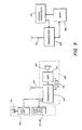
- FIG. 3 a simplified block diagram is presented, showing the major functional elements of the audio communications system of the present invention and the functional elements associated with a host device.
- the audio communications module 28 has telephone module 46 coupled thereto.
- the host device 68 may simply be a telephone base unit, similar to a standard cordless telephone unit, which is well known in the art.
- the host may be any source of audio communications, including a computer as illustrated in FIG. 3.
- the directional microphone 52 and preamplifier 62 provide a means for inputting audio communications to the transceiver 64, and the keypad 56 provides a means for inputting touch-tones.
- the transceiver 64 is a low power, short range FM transmitter/receiver, similar in design to the inexpensive units used in standard cordless telephones.
- the operating frequency of transceiver 64 is matched to that of a transceiver 66, coupled to the host device 68.
- An antenna 44 is mounted within audio communications module 25, as stated before, and a second antenna 70 is coupled to the second transceiver 66.
- the transceiver 64 demodulates the received signal and presents it amplifier 72, the output of which is used to drive the acoustic transducer 40.
- Power for the transceiver and amplifier are provided by rechargable power supply 74.
- the host device 68 is shown to be coupled to a speech processor 76.
- Speech processor 76 is simply a text-to-speech message facility.
- the host 68 outputs text in the form of ASCII character codes, and the speech processor 76 translates the codes into electrical signals which are representative of synthesized speech. These signals are transmitted via transceiver 66 to the audio communications module 28, where they are converted into sound.
- the audio communications module 28 provides no code translation functions itself.
- each audio communications module 28 In the typical office environment, a number of audio communications modules 28 will be in use at the same time, in the same building location, and quite possibly in adjacent offices. Where several modules are used, it is desirable for each audio communications module 28 to have its own assigned frequency, to avoid the problem of one user's audio messages being received by another user. In a building having many audio communications modules 28 at the same time, the number of allocated frequency necessary to prevent interference could be correspondingly great. It is therefore desirable to limit the power of the individual transceivers, so as to provide a range of approximately fifty feet, and thereby minimize the number of frequencies which must be allocated.
- the acoustic horn 42 is fabricated from plastic having sufficient thickness to provide rigidity and prevent unwanted resonance at sound frequencies generated by the acoustic transducer or otherwise absorb sound energy from the system.
- Cross members 80 extend laterally across mouth 78 to provide the horn with additional structural rigidity.
- the grill 30, which fits over the mouth 78 of the acoustic horn 42 is an acoustically transparent fabric, and prevents dust and foreign material does not drop into the horn 42.
- the acoustic horn 42 is positioned with its throat 79 at the output of acoustic transducer 40.
- the throat 79 is basically square, having a side dimension of .09 inches.
- the acoustic transducer 40 is a standard high-efficiency sound generator which receives an electrical signal input from amplifier 72, shown in FIG. 3.
- a horn type loudspeaker was chosen because it fulfilled the criteria deemed to be important to a device such as the audio communications module 28. It had to be a high fidelity system with low distortion and flat response over the predominant frequencies of the human voice audio spectrum. The sound quality of the output had to be very good to provide excellent intelligibility at low sound levels. It had to provide a directional audio output so as to minimize lateral sound dispersion, and hence the impact on users in adjacent office areas. It had to operate at high efficiency to conserve battery power. It had to be cost effective. Finally, it had to be a size that could be easily accommodated by the audio communications module 28.
- the acoustic horn 42 of the present invention has the primary functions of intensifying low level sound and shaping the sound to obtain optimal sound dispersion characteristics for the audio communications module 28.
- the acoustic horn 42 is an exponential flair type, as opposed to the conical type, to radiate low frequencies more efficiently.
- the acoustic horn 42 has a rectangular cross section, as can be seen with reference to FIG. 4. It is advantageous to maintain the thickness of the horn as nearly constant, due to the desirability of keeping the housing 36 of audio communications module 28 nearly flat.
- the width dimension is relatively long compared with its depth. In the preferred embodiment, the width is approximately 14.5 inches and the depth is approximately 1.5 inches. It is desirable that the mouth 78 be sufficiently wide so that a nearly even sound dispersal is provides across the entire width of the backrest 14. This will ensure that a user, sitting in the chair 10, will be able to clearly hear the sound emitted from the acoustic horn 42 as he moves his head freely in any position along the backrest 14. The smaller depth dimension ensures a desirable shaping of the sound contours, as illustrated in FIG. 5.
- acoustic horns provide higher efficiency due to the improved impedence match at the mouth of the horn that results from the increase in area from the throat to the mouth.
- the area difference permits relatively small piston displacements in the acoustic transducer 40, which reduce distortion and minimize the energy required to drive the system. A transducer this small will be relatively inexpensive.
- A(x) A0e mx
- A(x) the cross sectional area of the horn at a distance x from the throat
- A0 the cross sectional area of the throat of the horn
- the dimension x along the major axis, from the throat 79 to the mouth 78 is 12.0 inches.
- FIG. 5 illustrates the functioning of the acoustic horn 42, showing in particular the dispersion of sound in relationship to a user.
- the sound pressure levels contours 82 are shown to be directly upwardly toward the user's ears, while little sound is broadcast horizontally to disturb others in the environment.
- the user adjusts the volume control 32 to a level of sound comfort, usually slightly above to ambient sound level in an office environment, which is generally on the order of 25 to 30 decibels.
- the user now seated in the chair 10, can clearly hear audio messages emitted from the audio communications module 28 in privacy while others in the office environment will not be disturbed by additional noise.
- a person standing in the office, six to eight feet from chair 10, would have little awareness that the user of chair 10 is listening to an audio message.
- the user, seated in chair 10 has the freedom of movement to roll the chair around his office space and position his head variously, in relation to the backrest 14, while still hearing the audio messages.
- the user would, for example, dial a telephone number with with telephone module 46, mounted on the armrest 16, and make a connection.
- the directional microphone 52 aimed toward his head, the user would converse in normal voice levels, while listening in privacy.
- the invention could use the audio communications module alone, simply as a personal loudspeaker system. While it is a desirable feature to have the audio communications module be an add on feature for existing office chairs, thus reducing the cost, it is conceivable that office chairs could be advantageously manufactured with the audio communications system included within chair's basic structure, possibly integral with the backrest. Although the present invention is most useful in an office environment, it is further conceivable that the present invention could be used in fixed, or semi-fixed environments, such as in movie theaters or airliners, automobiles, and other vehicles, where the seats are stationary relative to the floor.
- the type of audio communications may not be considered limiting, as it is conceivable that the present invention may be used to receive broadcast sources, such as radio and television, as well as prerecorded entertainment or information sources, such as cassette tapes or dictaphone.
- broadcast sources such as radio and television
- prerecorded entertainment or information sources such as cassette tapes or dictaphone.
Landscapes
- Physics & Mathematics (AREA)
- Engineering & Computer Science (AREA)
- Acoustics & Sound (AREA)
- Signal Processing (AREA)
- Chair Legs, Seat Parts, And Backrests (AREA)
- Transceivers (AREA)
Applications Claiming Priority (2)
| Application Number | Priority Date | Filing Date | Title |
|---|---|---|---|
| US06/920,806 US4868888A (en) | 1986-10-17 | 1986-10-17 | Audio communications module for an office chair |
| US920806 | 1986-10-17 |
Publications (3)
| Publication Number | Publication Date |
|---|---|
| EP0264785A2 true EP0264785A2 (fr) | 1988-04-27 |
| EP0264785A3 EP0264785A3 (en) | 1990-04-18 |
| EP0264785B1 EP0264785B1 (fr) | 1994-01-05 |
Family
ID=25444444
Family Applications (1)
| Application Number | Title | Priority Date | Filing Date |
|---|---|---|---|
| EP87114952A Expired - Lifetime EP0264785B1 (fr) | 1986-10-17 | 1987-10-13 | Module de communication audio pour un siège de bureau |
Country Status (6)
| Country | Link |
|---|---|
| US (1) | US4868888A (fr) |
| EP (1) | EP0264785B1 (fr) |
| JP (1) | JP2527445B2 (fr) |
| AU (1) | AU600739B2 (fr) |
| CA (1) | CA1299662C (fr) |
| DE (1) | DE3788702T2 (fr) |
Cited By (6)
| Publication number | Priority date | Publication date | Assignee | Title |
|---|---|---|---|---|
| EP0538020A1 (fr) * | 1991-10-14 | 1993-04-21 | Fujitsu Limited | Chaise avec un clavier supplémentaire et système de clavier |
| FR2768099A1 (fr) * | 1997-09-05 | 1999-03-12 | Faure Bertrand Equipements Sa | Siege de vehicule dote de haut-parleurs |
| GB2330445A (en) * | 1997-10-14 | 1999-04-21 | Massoud Keyvan Fouladi | Communication and reproduction apparatus |
| FR2779313A1 (fr) * | 1998-05-27 | 1999-12-03 | Cyril Patrice Mougeot | Dispositif pour sonoriser des fauteuils permettant de creer une source sonore additive au son conventionnel |
| GB2358316A (en) * | 2000-01-15 | 2001-07-18 | Jan Sebastian Gale | Loudspeaker arrangement for an acoustic seat |
| FR2925186A1 (fr) * | 2007-12-12 | 2009-06-19 | Omelior Soc Par Actions Simpli | Procede de saisie de donnees et dispositif pour sa mise en oeuvre |
Families Citing this family (40)
| Publication number | Priority date | Publication date | Assignee | Title |
|---|---|---|---|---|
| US4982996A (en) * | 1989-02-17 | 1991-01-08 | Fiat Auto S.P.A. | Automotive seating system featuring a television set |
| SE466427B (sv) * | 1990-06-25 | 1992-02-10 | Ericsson Telefon Ab L M | Handfrigoeringsmodul foer en mobiltelefon |
| US5177616A (en) * | 1991-12-02 | 1993-01-05 | Matsushita Avionics Systems | Stowable video display assembly |
| US5318340A (en) * | 1992-02-05 | 1994-06-07 | Yorkshire Industries, Inc. | Conference center |
| US5398992A (en) * | 1992-02-05 | 1995-03-21 | The Walt Disney Company | Seat having sound system with acoustic waveguide |
| US5465422A (en) * | 1994-06-13 | 1995-11-07 | Dean; Mark A. | Seat apparatus for actuating an audio source |
| US5889875A (en) * | 1994-07-01 | 1999-03-30 | Bose Corporation | Electroacoustical transducing |
| USD374000S (en) | 1995-04-11 | 1996-09-24 | Wood David E | Chair mounted mouse pad |
| DE19524177C1 (de) * | 1995-07-03 | 1996-08-29 | Daimler Benz Ag | Armstütze für Fahrzeuge |
| US5887071A (en) * | 1996-08-07 | 1999-03-23 | Harman International Industries, Incorporated | Dipole speaker headrests |
| US6542758B1 (en) * | 1997-12-11 | 2003-04-01 | Ericsson Inc. | Distributed radio telephone for use in a vehicle |
| US6007150A (en) | 1998-03-08 | 1999-12-28 | Milsco Manufacturing Company | Motorcycle seat with adjustable backrest |
| US6092867A (en) * | 1998-04-23 | 2000-07-25 | Miller; Patrick | Gaming console |
| US6443473B1 (en) * | 1998-06-25 | 2002-09-03 | Cathy J. Lentz | Portable audio entertainment apparatus containing separately carried signal and sound producing portions |
| US6199948B1 (en) * | 1998-12-16 | 2001-03-13 | Johnson Controls Technology Company | Interchangeable module system |
| US6814709B2 (en) * | 2000-06-16 | 2004-11-09 | Brookstone Purchasing, Inc. | Massaging bed rest cushion with light |
| US20020178010A1 (en) * | 2001-05-22 | 2002-11-28 | Jack Weaver | Sound responsive service window |
| US6523894B1 (en) * | 2001-09-18 | 2003-02-25 | Leo Mellace | Beach chair with integral audio player |
| US20040217632A1 (en) * | 2003-05-03 | 2004-11-04 | Glassman Steven P. | Sound chair |
| US6923502B2 (en) * | 2003-07-28 | 2005-08-02 | Terry Cassaday | Chair with switch controls for chair control directory |
| US20050122067A1 (en) * | 2003-09-03 | 2005-06-09 | Monster, Llc | Action seating |
| CA2453221A1 (fr) * | 2003-12-16 | 2005-06-16 | Terry Cassaday | Bras de levier avec contour tactile |
| US7328470B2 (en) * | 2004-02-20 | 2008-02-12 | Brookstone Purchasing, Inc. | Foldable massaging bed rest |
| US11011153B2 (en) | 2004-03-01 | 2021-05-18 | Blackberry Limited | Communications system providing automatic text-to-speech conversion features and related methods |
| US8538386B2 (en) * | 2004-03-01 | 2013-09-17 | Blackberry Limited | Communications system providing text-to-speech message conversion features using audio filter parameters and related methods |
| US7650170B2 (en) | 2004-03-01 | 2010-01-19 | Research In Motion Limited | Communications system providing automatic text-to-speech conversion features and related methods |
| US7431392B2 (en) * | 2006-09-26 | 2008-10-07 | True Seating Concepts, Llc | Chair having built-in audio speakers and a slide-out compartment for a portable digital storage and playback device |
| US20080100107A1 (en) * | 2006-10-31 | 2008-05-01 | Paslawski Ray N | Folding chair having integrated audio port |
| US20080262657A1 (en) * | 2007-04-17 | 2008-10-23 | L&P Property Management Company | System and method for controlling adjustable furniture |
| USD608557S1 (en) * | 2009-03-27 | 2010-01-26 | Aishin Co., Ltd. | Office chair |
| US8858343B2 (en) * | 2009-11-09 | 2014-10-14 | Igt | Server-based gaming chair |
| US9603496B1 (en) | 2013-03-15 | 2017-03-28 | David C. Hartman | Toilet seat assembly |
| US9603457B2 (en) | 2013-05-31 | 2017-03-28 | Steelcase Inc. | Lounge assemblies for supporting portable electronics devices |
| GB2546312B (en) * | 2016-01-15 | 2018-02-14 | Sony Interactive Entertainment Inc | Entertainment device accessory |
| CN115284990B (zh) * | 2016-10-28 | 2024-10-22 | 伯斯有限公司 | 具有声学通道的靠背扬声器 |
| WO2019005880A1 (fr) | 2017-06-27 | 2019-01-03 | Shanghai Yanfeng Jinqiao Automotive Trim Systems Co. Ltd. | Composant d'intérieur de véhicule |
| US10999679B1 (en) * | 2019-01-18 | 2021-05-04 | Joseph Savovic | Personal sound amplification seating |
| US11647327B2 (en) | 2020-06-01 | 2023-05-09 | Bose Corporation | Backrest speakers |
| US11590869B2 (en) | 2021-05-28 | 2023-02-28 | Bose Corporation | Seatback speakers |
| US11659947B2 (en) * | 2020-10-15 | 2023-05-30 | Bertha Stephanie Martinez | Shoe holder organizer |
Family Cites Families (21)
| Publication number | Priority date | Publication date | Assignee | Title |
|---|---|---|---|---|
| CA719120A (en) * | 1965-10-05 | Straumann Fred | Detachable armrest for automobile seats | |
| GB225604A (en) * | 1923-08-29 | 1924-12-01 | Edward Alfred Graham | Improvements in or relating to portable loud speaking telephonic apparatus |
| US1864615A (en) * | 1929-12-06 | 1932-06-28 | Rca Corp | Sound reproducing apparatus |
| US2370359A (en) * | 1942-09-29 | 1945-02-27 | Marvin E Mccart | Beauty parlor appliance |
| DE1014167B (de) * | 1955-08-03 | 1957-08-22 | Telefunken Gmbh | Ohrensessel mit eingebauten Lautsprechern |
| US3928723A (en) * | 1973-07-02 | 1975-12-23 | Kazuo Kai | Telephone set with built-in loudspeaker |
| US3851123A (en) * | 1973-10-19 | 1974-11-26 | Motorola Inc | Mechanical audio coupling device |
| DE7508842U (de) * | 1974-12-20 | 1976-01-02 | Blaupunkt-Werke Gmbh, 3200 Hildesheim | Kopfstuetze mit lautsprecher |
| US3976162A (en) * | 1975-04-07 | 1976-08-24 | Lawrence Peska Associates, Inc. | Personal speaker system |
| US4023566A (en) * | 1975-10-10 | 1977-05-17 | Martinmaas Werner W | Body-supporting means with adjustable vibratory means in the audible frequency range |
| DE7538667U (de) * | 1975-12-04 | 1976-06-10 | Iven, Gerd, 4000 Duesseldorf | Lautsprecherkoerper |
| DE2628216C2 (de) * | 1976-06-23 | 1983-01-13 | Daimler-Benz Ag, 7000 Stuttgart | Anordnung eines Fernsprechgeräts in einem Kraftfahrzeug |
| US4142312A (en) * | 1977-03-08 | 1979-03-06 | Bell Telephone Laboratories, Incorporated | Station set for mobile radiotelephone units |
| DE3025691A1 (de) * | 1980-07-07 | 1982-02-04 | Wilhelm Dr.-Ing. 5340 Bad Honnef Lepper | Lautsprecheranordnung in boxen |
| JPS58119282U (ja) * | 1982-02-04 | 1983-08-13 | ボデイソニツク株式会社 | 臨場感再現装置 |
| DE3331946A1 (de) * | 1983-09-05 | 1984-05-17 | Bernd F. 7972 Isny Blome | Phono-luxussessel |
| JPS6066139U (ja) * | 1983-10-14 | 1985-05-10 | 松下電器産業株式会社 | 車載無線機用音響装置 |
| US4584603A (en) * | 1984-10-19 | 1986-04-22 | Harrison Elden D | Amusement and information system for use on a passenger carrier |
| AU5839086A (en) * | 1985-06-14 | 1986-12-18 | Michael Cuffe | Keyboards mounted on chair armrests |
| AU7467587A (en) * | 1986-06-25 | 1988-01-07 | Michael Cuffe | Arm rest keyboard |
| US5046257A (en) * | 1990-01-19 | 1991-09-10 | Marshall Forrest A | Determining and marking apparatus and method for use in optometry and ophthalmology |
-
1986
- 1986-10-17 US US06/920,806 patent/US4868888A/en not_active Expired - Fee Related
-
1987
- 1987-08-10 AU AU76713/87A patent/AU600739B2/en not_active Ceased
- 1987-10-13 JP JP62258185A patent/JP2527445B2/ja not_active Expired - Lifetime
- 1987-10-13 EP EP87114952A patent/EP0264785B1/fr not_active Expired - Lifetime
- 1987-10-13 DE DE3788702T patent/DE3788702T2/de not_active Expired - Fee Related
- 1987-10-16 CA CA000549463A patent/CA1299662C/fr not_active Expired - Lifetime
Cited By (9)
| Publication number | Priority date | Publication date | Assignee | Title |
|---|---|---|---|---|
| EP0538020A1 (fr) * | 1991-10-14 | 1993-04-21 | Fujitsu Limited | Chaise avec un clavier supplémentaire et système de clavier |
| US5818357A (en) * | 1991-10-14 | 1998-10-06 | Fujitsu Limited | Chair with a supplemental keyboard and a keyboard system |
| FR2768099A1 (fr) * | 1997-09-05 | 1999-03-12 | Faure Bertrand Equipements Sa | Siege de vehicule dote de haut-parleurs |
| GB2330445A (en) * | 1997-10-14 | 1999-04-21 | Massoud Keyvan Fouladi | Communication and reproduction apparatus |
| GB2330445B (en) * | 1997-10-14 | 2002-04-10 | Massoud Keyvan Fouladi | Communication apparatus |
| FR2779313A1 (fr) * | 1998-05-27 | 1999-12-03 | Cyril Patrice Mougeot | Dispositif pour sonoriser des fauteuils permettant de creer une source sonore additive au son conventionnel |
| GB2358316A (en) * | 2000-01-15 | 2001-07-18 | Jan Sebastian Gale | Loudspeaker arrangement for an acoustic seat |
| GB2358316B (en) * | 2000-01-15 | 2002-07-31 | Jan Sebastian Gale | Improvements in relating to acoustic seating |
| FR2925186A1 (fr) * | 2007-12-12 | 2009-06-19 | Omelior Soc Par Actions Simpli | Procede de saisie de donnees et dispositif pour sa mise en oeuvre |
Also Published As
| Publication number | Publication date |
|---|---|
| DE3788702T2 (de) | 1994-06-16 |
| AU600739B2 (en) | 1990-08-23 |
| DE3788702D1 (de) | 1994-02-17 |
| EP0264785B1 (fr) | 1994-01-05 |
| JP2527445B2 (ja) | 1996-08-21 |
| AU7671387A (en) | 1988-04-21 |
| JPS63108821A (ja) | 1988-05-13 |
| US4868888A (en) | 1989-09-19 |
| CA1299662C (fr) | 1992-04-28 |
| EP0264785A3 (en) | 1990-04-18 |
Similar Documents
| Publication | Publication Date | Title |
|---|---|---|
| EP0264785B1 (fr) | Module de communication audio pour un siège de bureau | |
| US11869526B2 (en) | Hearing enhancement methods and systems | |
| EP0947121B1 (fr) | Dispositif incorporant un transducteur electroacoustique aux fins d'une reproduction optimale de la parole | |
| JP3499239B2 (ja) | 単指向性イヤー・マイクロフォン及び方法 | |
| CA2099945C (fr) | Structure de casque telephonique pour reduire le bruit ambiant | |
| US7801570B2 (en) | Directional speaker for portable electronic device | |
| US7072476B2 (en) | Audio headset | |
| US5909498A (en) | Transducer device for use with communication apparatus | |
| US6891286B2 (en) | Magnetostrictive actuator | |
| JP2025032214A (ja) | ラウドスピーカ装置 | |
| US20030152245A1 (en) | Chair equipped with a speaker | |
| US4555592A (en) | Wireless hands-free conference telephone system | |
| CN207916655U (zh) | 便于听取语音信息的音频装置、头枕、枕套、颈枕、座椅 | |
| WO1994023521A1 (fr) | Microphone d'oreille unidirectionnel et joint | |
| EP4122215B1 (fr) | Haut-parleur | |
| CA2290486A1 (fr) | Systeme d'information des passagers | |
| WO2002007477A2 (fr) | Casque audio | |
| EP1206161A1 (fr) | Réseau de microphones avec une directivité auto-réglable pour des combinés téléphoniques et dispositifs mains libres | |
| US9967672B2 (en) | Audio system | |
| EP0692169A1 (fr) | Microphone d'oreille unidirectionnel a orifices multiples | |
| JPH05345549A (ja) | 車両用音響装置 | |
| JP3242045B2 (ja) | 座席用通信装置 | |
| US9681221B2 (en) | Delegate unit and conference system with the delegate unit |
Legal Events
| Date | Code | Title | Description |
|---|---|---|---|
| PUAI | Public reference made under article 153(3) epc to a published international application that has entered the european phase |
Free format text: ORIGINAL CODE: 0009012 |
|
| AK | Designated contracting states |
Kind code of ref document: A2 Designated state(s): BE DE FR GB |
|
| PUAL | Search report despatched |
Free format text: ORIGINAL CODE: 0009013 |
|
| AK | Designated contracting states |
Kind code of ref document: A3 Designated state(s): BE DE FR GB |
|
| 17P | Request for examination filed |
Effective date: 19901017 |
|
| 17Q | First examination report despatched |
Effective date: 19920513 |
|
| GRAA | (expected) grant |
Free format text: ORIGINAL CODE: 0009210 |
|
| AK | Designated contracting states |
Kind code of ref document: B1 Designated state(s): BE DE FR GB |
|
| REF | Corresponds to: |
Ref document number: 3788702 Country of ref document: DE Date of ref document: 19940217 |
|
| ET | Fr: translation filed | ||
| PLBE | No opposition filed within time limit |
Free format text: ORIGINAL CODE: 0009261 |
|
| STAA | Information on the status of an ep patent application or granted ep patent |
Free format text: STATUS: NO OPPOSITION FILED WITHIN TIME LIMIT |
|
| 26N | No opposition filed | ||
| PGFP | Annual fee paid to national office [announced via postgrant information from national office to epo] |
Ref country code: BE Payment date: 19950925 Year of fee payment: 9 |
|
| PG25 | Lapsed in a contracting state [announced via postgrant information from national office to epo] |
Ref country code: BE Effective date: 19961031 |
|
| BERE | Be: lapsed |
Owner name: WANG LABORATORIES INC. Effective date: 19961031 |
|
| PGFP | Annual fee paid to national office [announced via postgrant information from national office to epo] |
Ref country code: FR Payment date: 19990917 Year of fee payment: 13 |
|
| PGFP | Annual fee paid to national office [announced via postgrant information from national office to epo] |
Ref country code: GB Payment date: 19990920 Year of fee payment: 13 Ref country code: DE Payment date: 19990920 Year of fee payment: 13 |
|
| PG25 | Lapsed in a contracting state [announced via postgrant information from national office to epo] |
Ref country code: GB Free format text: LAPSE BECAUSE OF NON-PAYMENT OF DUE FEES Effective date: 20001013 |
|
| GBPC | Gb: european patent ceased through non-payment of renewal fee |
Effective date: 20001013 |
|
| PG25 | Lapsed in a contracting state [announced via postgrant information from national office to epo] |
Ref country code: FR Free format text: LAPSE BECAUSE OF NON-PAYMENT OF DUE FEES Effective date: 20010629 |
|
| PG25 | Lapsed in a contracting state [announced via postgrant information from national office to epo] |
Ref country code: DE Free format text: LAPSE BECAUSE OF NON-PAYMENT OF DUE FEES Effective date: 20010703 |
|
| REG | Reference to a national code |
Ref country code: FR Ref legal event code: ST |