EP0264832B1 - Procédé et dispositif de contrôle de la stabilité structurelle d'un matériau laminé - Google Patents
Procédé et dispositif de contrôle de la stabilité structurelle d'un matériau laminé Download PDFInfo
- Publication number
- EP0264832B1 EP0264832B1 EP87115096A EP87115096A EP0264832B1 EP 0264832 B1 EP0264832 B1 EP 0264832B1 EP 87115096 A EP87115096 A EP 87115096A EP 87115096 A EP87115096 A EP 87115096A EP 0264832 B1 EP0264832 B1 EP 0264832B1
- Authority
- EP
- European Patent Office
- Prior art keywords
- sensor
- laminated body
- dimensioning
- shaft
- supporting plate
- Prior art date
- Legal status (The legal status is an assumption and is not a legal conclusion. Google has not performed a legal analysis and makes no representation as to the accuracy of the status listed.)
- Expired
Links
Images




Classifications
-
- G—PHYSICS
- G01—MEASURING; TESTING
- G01B—MEASURING LENGTH, THICKNESS OR SIMILAR LINEAR DIMENSIONS; MEASURING ANGLES; MEASURING AREAS; MEASURING IRREGULARITIES OF SURFACES OR CONTOURS
- G01B5/00—Measuring arrangements characterised by the use of mechanical techniques
- G01B5/30—Measuring arrangements characterised by the use of mechanical techniques for measuring the deformation in a solid, e.g. mechanical strain gauge
-
- G—PHYSICS
- G01—MEASURING; TESTING
- G01B—MEASURING LENGTH, THICKNESS OR SIMILAR LINEAR DIMENSIONS; MEASURING ANGLES; MEASURING AREAS; MEASURING IRREGULARITIES OF SURFACES OR CONTOURS
- G01B7/00—Measuring arrangements characterised by the use of electric or magnetic techniques
- G01B7/16—Measuring arrangements characterised by the use of electric or magnetic techniques for measuring the deformation in a solid, e.g. by resistance strain gauge
Definitions
- This invention relates to a method and apparatus for measuring planar dimensional changes in flat, flexible materials, such as soft laminated carpet and carpet tile materials, when subjected to changes in ambient temperature and moisture.
- the primary layer and the backing layer it is usually necessary to pre-stretch the primary layer and the backing layer to smooth out wrinkles and obtain an even surface for the application of the adhesive and subsequent mating of the layers.
- the stretching step may cause flaws in the structural integrity and stability of the laminate, since the binders that anchor the pile fibers in the primary layers are unlikely to have the same elastic properties as the heavy tile backing and bonding adhesive layers.
- GB 1,276,718 discloses a method for the quantitative analysis of strain induced in a component subject to a load, for example, a component of an internal combustion engine.
- transducers similar to those described in the present invention are used in the measuring circuit, they are designed to measure the high levels of strain and torque of the engine parts. They are not accurate enough or sensitive enough for the delicate monitoring of micromovements of a carpet or carpet laminate.
- a method for evaluating the structural integrity and stability of such soft laminated bodies including the steps of locating the laminated body on a rigid supporting surface, supporting a displacement sensor above the fixed lamination component, the sensor having a fixed element rigidly connected to a reference position fixed with respect to the laminated body and a displacable element rigidly linked to a dimensioning element, the sensor producing output that is responsive to displacement of the movable element relative to the fixed element, connecting the dimensioning element to the lamination component at a point spaced from the reference position, and recording indications of displacement that are output from the sensor, is characterized in that the laminated body is placed in a testing area on the support, the dimensioning element is connected to the laminated body by penetrating it to a predetermined depth by pointed probes projecting downward from the dimensioning element, the laminated body is exposed to change in ambient conditions in the testing area, and the recorded measure of displacement of the movable element is compared with standards representing structural characteristics within the laminated body.
- the invention provides a testing procedure for evaluating stresses or residual tensions imposed on the components of soft laminated bodies such as carpet tile, and therefore their overall quality and stability. Preferably such tests are carried out with the tile in the face down position although the use of the method described is not so limited.
- an apparatus for carrying out the above-defined method for evaluating the structural integrity of such soft laminated bodies including a rigid testing area for the body to be evaluated, a sensor having a fixed element above and adapted to be rigidly connected to the laminated body by a supporting member located in a fixed reference position and a movable element rigidly connected to a dimensioning element, the sensor producing output that is responsive to displacement of the movable element, the dimensioning element being adapted to be connected to the the body to be evaluated at a point spaced from the support position, and recording means for storing the indications of displacement that are output from the sensor, is characterized in that a testing area is located on the support under the dimensioning element to receive the body to be evaluated, the dimensioning element includes a pointed probe projecting downward and adapted to penetrate the body to be evaluated to a predetermined depth, and temperature-controlling means are provided for adjusting the ambient temperature in the testing area.
- the fixed reference position is located inside the periphery of the testing area and is a pointed pin extending from the end of a supporting member and inserted through the layers of the laminated body to prevent relative movement between the sensor finger and the laminated body, the latter having a supporting collar or stop that is supported on the surface of the laminated body.
- the three sensors and dimensioning elements are radially located on a sensor supporting plate having corresponding slots to slidably receive the linkages between the sensors and the dimensioning elements.
- FIG. 1 shows the slotted supporting plate (18) comprising the three fingers (5) (which of course could be integrated into a single plate having three slots).
- a sensing unit comprising a movable dimensioning element including locating means (not shown in Figure 1), a linking shaft (11), and a sensor (shown only in part and in phantom), in the form of an inductive transducer having a fixed element rigidly connected to its supporting finger by a clamp (14) in the form of an inverted U and screws (27), and electrically connected to a conventional recording device (29) (shown schematically).
- the linkage coupling block is T-shaped in section with its lower part being slidably received in slot (21A) and its upper part being secured to one end of linking shaft (11) by set screw (16).
- the other end of the linking shaft is threaded into a plunger (13) (shown in phantom), which constitutes the movable element of the transducer.
- the plunger (13) is aligned for reciprocal movement within an impedence coil (not shown in Figure 1) that constitutes the fixed element of the transducer, the output of which is responsive to displacement of the movable element relative to the fixed element.
- the current flow induced by movement of the dimensioning element, linking shaft (11) and plunger (13) is passed through the leads (4) to the recording device (29), which may be a movable stylus and paper roll, using a horizontal time axis, or an electronic recorder.
- the information can be conveniently computerized and recorded as dimensional change on a percentage basis, and the individual outputs of each of the elements can be integrated into data reflecting the angular relationships of the fingers (5).
- FIG. 2 illustrates further details of a sensor finger of the type shown in Figure 1, identical arabic numbers indicating the same or similar components but with the suffix "A".
- Vertical column (7A) being fixed in a reference position by the penetration of its pin extension through the layers of the laminated body, to prevent relative movement between finger 5(A) and the laminated body to be tested, ensures that the fixed element of the transducer is adapted to be rigidly connected to the laminated body.
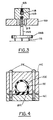
- the movable dimensioning element shown includes three pointed probes (17A) (shown in detail in Figure 3) projecting downward from a leveling disk 24(A) and adapted to penetrate the body to be evaluated to a predetermined depth; they are threadably connected by stud 28(A) to a linkage coupling block (10) (shown partly in phantom).
- the probes (17A) are shown superficially resting on the upper surface of a carpet tile in face down orientation, ready for penetration into the tile to evaluate distortions or residual tensions from a prior annealing step (see Example); also shown in Figure 2 are optional ridges (19A) for positioning the tile within an optional test tank (2A), in which the tile is shown immersed in water (25A).
- the ambient temperature can be controlled by placing the entire unit in an oven , with or without the tank (2A).
- the alignment of the linking shafts (11) and plungers (13) with the respective impedence coils is achieved by turning the threaded supports 38(A) to adjust the level of the slotted ends of fingers 5(A) with respect to the height of the column 7(A) at its other end.
- FIG. 3 illustrates additional details of the end structure of one of the slotted ends of supporting frame (18B), having slot (21B), through which endthreaded stud (28B) connects the leveling disk (24B) to the coupling block (10B), which is secured onto the distal end of linking shaft (11B) by set screw (16B).
- the distance between the linking shaft and the bottom faces of the upper flanges of the linkage coupling block is such that the said faces rest on the finger 5(B) when the the linking shaft and plunger (13) are in proper alignment with the associated impedence coil.
- FIG. 4 shows additional details of the structure of the impedence coil and plunger (13C) (in blank schematic), in which the coil is insulated by rubber pads (20C) and held in place by clamp (14C) and screws (27C).
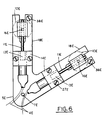
- FIG. 5 shows additional details of the modified version of the device shown in Figure 1, in which three separate sensor fingers (5D), replacing sensor-supporting plate (18), are rotatably and slidably mounted on a vertical extension of supporting column 7D.
- the fingers (5D) are of different lengths and each is separately adjustable to control the location of the pointed end of one of the threaded probes (17D) to permit controlled penetration into different laminate layers or components at desired positions; this is variously accomplished by manual vertical adjustment and rotation of fingers (5D), use of locking nuts (9D), and adjustment to horizontal configuration by use of adjustments in modified threaded vertical supporting column (7D).
- the depth of probe penetration desired depends upon the the orientation, face up or down, of the laminated body and the nature of the information desired.
- Supporting column (7D) includes a horizontal flange secured to the base (8D) that serves to maintain it in a vertical position and the fingers (5D) in an accurately horizontal position.
- the fixed reference position for fingers (5D) is located outside the periphery of the testing area and therefore ridges, such as those shown in Figure 2 as (19A), or other protuberances are required within the test area to secure the laminated body against movement relative to the reference location of supporting column (7D).
- the induction transducers or other sensor units as shown in Figures 1, 2 and 4, and the recording means shown in Figure 1 will be the same.
- Preferred positions for such three-fingered devices are at 45° with orientation along the length, the width, and on the diagonal of the test laminate or tile, at least one arm preferably being in a machine direction.
- the following example describes tests on eight unannealed nylon-faced carpet tiles obtained from Burlington Industries, Glasgow, Virginia, from the same batch number, having EVA-based backing weighing 254.0 gm/m2 (75oz/1yd2) adhered with a standard hot melt adhesive weighing 102 gm/m2 (30oz/yd2).
- the tile samples hereinafter identified as S-1 through S-8, are annealed at 93.3°C (200°F) for periods varying from 5 minutes to 20 minutes, then air cooled to room temperature, and tested, using a testing device essentially the same as that described in Figures 1-4.
- No water-filled test tank (2) is used, and the device (except recording device (29)) is mounted wholly within a thermostatically-controlled hot air oven.
- Each test tile is set face down in tank (2) and heated at a rate of about -6.7°C (20°F) per minute up to 60°C (140°F). After two (2) hours the oven is cooled at the same rate to ambient temperature.
Landscapes
- Physics & Mathematics (AREA)
- General Physics & Mathematics (AREA)
- Treatment Of Fiber Materials (AREA)
- Investigating Strength Of Materials By Application Of Mechanical Stress (AREA)
- Testing Of Devices, Machine Parts, Or Other Structures Thereof (AREA)
Claims (7)
- Procédé pour évaluer l'intégrité et la stabilité structurelles de corps stratifiés lisses, comprenant les étapes de positionnement du corps stratifié (3A) sur une surface support rigide (8A), supportant un détecteur (13A) au-dessus du corps stratifié fixe, le détecteur ayant un élément fixe (14A) lié rigidement au corps stratifié (3A) par une plaque support de détecteur (18A) supportée par une colonne (7A) positionnée en position de référence fixe par rapport au corps stratifié, et un arbre (11A) lié rigidement à un élément de mesure (24A + 17A), le détecteur produisant une sortie en réponse au déplacement de l'arbre (11A) par rapport à la colonne (7A), liant l'élément de mesure au corps stratifié à un point espacé de la colonne (7A), et enregistrant les indications de déplacement qui sont sorties du détecteur, caractérisé en ce que le corps stratifié est positionné sur une zone de tests, sur une surface support rigide (8A), l'élément de mesure est connecte au corps stratifié en y pénètrant d'une profondeur prédéterminée par des sondes pointues (17A) se projetant vers le bas à partir de l'élément de mesure, le corps stratifié (3A) est exposé aux modifications des conditions ambiantes dans la zone de test, et la mesure du déplacement enregistrée de l'arbre (11A), est comparée avec les caractéristiques standards de structure dans le corps stratifié.
- Dispositif pour exécuter le procédé selon la revendication 1, comprenant une surface de tests sur une surface support rigide (8A) pour le corps stratifié (3A) à évaluer, un détecteur (13A) ayant un élément fixe (14A) au-dessus et conçu pour être connecté rigidement au corps stratifié (3A) par une plaque support de détecteur (18A) supportée par la colonne (7A) positionnée en position de référence fixe et un arbre (11A) rigidement relié à un élément de mesure (24A + 17A), le détecteur (13A) produisant une sortie en réponse au déplacement de l'arbre (11A), l'élément de mesure étant conçu pour être lié au corps stratifié (3A) à évaluer, en un point espacé de la colonne (7A), et des moyens d'enregistrement pour enregistrer les indications du déplacement qui sont émises par le détecteur, caractérisé en ce que ladite surface de tests est positionnée sur la surface support rigide (8A) sous l'élément de mesure pour recevoir le corps à évaluer, l'élément de mesure comporte des sondes pointues (17A) se projetant vers le bas et conçues pour pénétrer le corps à évaluer d'une profondeur prédéterminée, et des moyens de commande de température sont fournis pour régler la température ambiante dans la surface de tests.
- Dispositif selon la revendication 2, caractérisé de plus en ce que la colonne (7A) est positionnée à l'intérieur du périmètre de la surface de tests et s'étend depuis l'extrémité de la plaque support de détecteurs (18A), et est insérée à travers les couches du corps stratifié (3A), pour empêcher le mouvement relatif entre les sondes pointues (17A) et le corps stratifié (3A).
- Dispositif selon l'une quelconque des revendications 2 ou 3, caractérisé de plus en ce que trois détecteurs (13A) et des éléments de mesure (24A + 17A) sont positionnés radialement sur une plaque support de détecteurs (18A), ayant des fentes correspondantes pour recevoir de manière coulissante les liaisons entre les détecteurs (13A) et les éléments de mesure respectifs.
- Dispositif selon l'une quelconque des revendications 2, 3 ou 4, caractérisé de plus en ce que la plaque support de détecteurs (18A) est sous forme de trois doigts joints, supportant chacun l'un des détecteurs (13A), et aligné radialement avec l'élément de mesure associé (24A + 17A).
- Dispositif selon l'une quelconque des revendications 4 ou 5, caractérisé de plus en ce que chacune des liaisons entre les détecteurs (13A) et les éléments de mesure respectifs (24A + 17A) comprend un arbre (11A) reliant le détecteur (13A) à un bloc d'accouplement de liaison (10A) et la plaque support de détecteurs (18A) a des moyens supports réglables à l'extrémité adjacente aux fentes conçu pour régler la hauteur de la fente au-dessus du corps stratifié, de façon à ce que l'arbre (11A) soit aligné convenablement avec l'élément fixe (14A) du détecteur.
- Dispositif selon la revendication 6, caractérisé de plus en ce que chaque bloc d'accouplement de liaison (10A) est dimensionné de telle façon qu'il présente une surface conçue pour coulisser sur la plaque support de détecteurs (18A), lorsque l'arbre (11A) est aligné convenablement avec l'élément fixe (14A) du détecteur (13A).
Applications Claiming Priority (4)
| Application Number | Priority Date | Filing Date | Title |
|---|---|---|---|
| US91941386A | 1986-10-16 | 1986-10-16 | |
| US07/044,687 US4750374A (en) | 1986-10-16 | 1987-05-01 | Process and apparatus for monitoring laminate structural stability |
| US44687 | 1993-04-12 | ||
| US919413 | 1997-08-27 |
Publications (3)
| Publication Number | Publication Date |
|---|---|
| EP0264832A2 EP0264832A2 (fr) | 1988-04-27 |
| EP0264832A3 EP0264832A3 (en) | 1989-04-26 |
| EP0264832B1 true EP0264832B1 (fr) | 1992-12-30 |
Family
ID=26721879
Family Applications (1)
| Application Number | Title | Priority Date | Filing Date |
|---|---|---|---|
| EP87115096A Expired EP0264832B1 (fr) | 1986-10-16 | 1987-10-15 | Procédé et dispositif de contrôle de la stabilité structurelle d'un matériau laminé |
Country Status (4)
| Country | Link |
|---|---|
| US (1) | US4750374A (fr) |
| EP (1) | EP0264832B1 (fr) |
| CA (1) | CA1322868C (fr) |
| DE (1) | DE3783311T2 (fr) |
Families Citing this family (9)
| Publication number | Priority date | Publication date | Assignee | Title |
|---|---|---|---|---|
| FR2653886B1 (fr) * | 1989-10-30 | 1992-02-07 | Aerospatiale | Appareil pour determiner le coefficient de dilatation hydrique des elements d'une structure composite. |
| US5756026A (en) * | 1996-01-05 | 1998-05-26 | Fiberco, Inc. | Method for control of post molding fabric curl and distortion |
| SE506383C2 (sv) * | 1996-04-24 | 1997-12-08 | Anders Loennoe | Anordning för mätning av skjuvning i kärnan hos en sandwichkonstruktion |
| JP2003166924A (ja) * | 2001-11-29 | 2003-06-13 | Nippon Sheet Glass Co Ltd | 往復摩耗試験機 |
| US20040137191A1 (en) * | 2003-01-15 | 2004-07-15 | Beren James R. | Recyclable extrusion-coated carpet having improved fiber lock |
| ITFI20080223A1 (it) * | 2008-11-17 | 2010-05-18 | Stardax S R L | Dispositivo e procedimento per la rilevazione o la generazione di una curvatura |
| US8474323B1 (en) | 2009-09-01 | 2013-07-02 | Honda Motor Co., Ltd. | Carpet deflection measurement device |
| CN102564283A (zh) * | 2011-12-19 | 2012-07-11 | 天津大学 | 用于木结构梁弯曲试验挠度测试的u型架 |
| CN119468896B (zh) * | 2024-11-08 | 2025-09-23 | 清华大学深圳国际研究生院 | 一种柔性应变传感器及其制备方法 |
Family Cites Families (15)
| Publication number | Priority date | Publication date | Assignee | Title |
|---|---|---|---|---|
| US2405167A (en) * | 1943-09-03 | 1946-08-06 | American Cyanamid Co | Apparatus for fluid treating under controlled conditions |
| US2766624A (en) * | 1954-01-04 | 1956-10-16 | Gen Motors Corp | Test chamber |
| US3001291A (en) * | 1956-07-19 | 1961-09-26 | Saab Scania Ab | Extensometers |
| US3319338A (en) * | 1965-05-10 | 1967-05-16 | Instron Corp | Extensometer |
| GB1276718A (en) * | 1969-12-10 | 1972-06-07 | Ricardo & Co Engineers | Improvements relating to analysis of strain in loaded components |
| US3729985A (en) * | 1972-02-09 | 1973-05-01 | C Sikorra | Strain gage |
| SU523324A1 (ru) * | 1972-07-21 | 1976-07-30 | Институт Проблем Прочности Ан Украинской Сср | Установка дл климатических испытаний элементов строительных конструкций |
| US3995476A (en) * | 1975-12-30 | 1976-12-07 | The United States Of America As Represented By The Administrator Of The National Aeronautics And Space Administration | Miniature biaxial strain transducer |
| IL54277A0 (en) * | 1978-03-14 | 1978-06-15 | Yissum Res Dev Co | Measurement of elasticity |
| DE2837945C2 (de) * | 1978-08-31 | 1985-10-10 | Elan-Schaltelemente Kurt Maecker Gmbh, 4040 Neuss | Dehnungsgeber |
| US4211013A (en) * | 1978-09-12 | 1980-07-08 | Phillips Petroleum Company | Gauge |
| US4410686A (en) * | 1981-12-21 | 1983-10-18 | The Dow Chemical Company | Norbornyl modified polyesteramides and process for preparing same |
| US4476727A (en) * | 1982-08-17 | 1984-10-16 | Hawk Marion N | Method of materials testing |
| US4566335A (en) * | 1984-08-16 | 1986-01-28 | Shell Oil Company | Method and apparatus for testing fiber reinforced plastic laminates |
| US4601941A (en) * | 1984-09-07 | 1986-07-22 | Shell Oil Company | High heat metal-polymer laminate |
-
1987
- 1987-05-01 US US07/044,687 patent/US4750374A/en not_active Expired - Lifetime
- 1987-10-15 EP EP87115096A patent/EP0264832B1/fr not_active Expired
- 1987-10-15 DE DE8787115096T patent/DE3783311T2/de not_active Expired - Fee Related
- 1987-10-16 CA CA000549531A patent/CA1322868C/fr not_active Expired - Fee Related
Also Published As
| Publication number | Publication date |
|---|---|
| EP0264832A3 (en) | 1989-04-26 |
| EP0264832A2 (fr) | 1988-04-27 |
| DE3783311D1 (de) | 1993-02-11 |
| US4750374A (en) | 1988-06-14 |
| DE3783311T2 (de) | 1993-04-15 |
| CA1322868C (fr) | 1993-10-12 |
Similar Documents
| Publication | Publication Date | Title |
|---|---|---|
| Phillips et al. | An experimental investigation of yield surfaces at elevated temperatures | |
| US4699000A (en) | Automated device for determining and evaluating the mechanical properties of materials | |
| EP0264832B1 (fr) | Procédé et dispositif de contrôle de la stabilité structurelle d'un matériau laminé | |
| US2154280A (en) | Accelerated creep testing apparatus | |
| US2356763A (en) | Method and means for testing materials | |
| US7441466B2 (en) | Weight sensor | |
| Voisey et al. | Laboratory measurements of eggshell strength: 1. An instrument for measuring shell strength by quasi-static compression, puncture, and non-destructive deformation | |
| CN101865646A (zh) | 热变形检测仪 | |
| US4354764A (en) | Specimen testing apparatus | |
| US4899102A (en) | Electrode system for a parallel plate dielectric analyzer | |
| US4116048A (en) | Hardness tester | |
| US5610515A (en) | Eddy current test method for residual stress in non-ferromagnetic metal objects | |
| CN112444459A (zh) | 一种用于发动机波形弹簧应力松弛试验的试验设备及方法 | |
| Darlington et al. | An apparatus for the measurement of tensile creep and contraction ratios in small non-rigid specimens | |
| US4855667A (en) | Parallel plate dielectric analyzer | |
| EP0984273A2 (fr) | Dispositif et méthode de mesure des propriétés thermophysiques de matériaux solides | |
| CN201748898U (zh) | 热变形检测仪 | |
| US3369390A (en) | Apparatus for testing strain | |
| JPH0611435A (ja) | 粘着性試験装置および方法 | |
| CN102393334A (zh) | 热变形检测仪 | |
| CN118707276A (zh) | 一种控制探测器的探头与晶圆之间距离的方法和装置 | |
| JPS63109311A (ja) | 積層構造の安定性を検査する方法と装置 | |
| CN223580985U (zh) | 一种同步测量薄膜厚度和弹性模量的装置 | |
| CN1026031C (zh) | 高聚物及其复合材料的应力跟踪测试仪器 | |
| JPH0110584Y2 (fr) |
Legal Events
| Date | Code | Title | Description |
|---|---|---|---|
| PUAI | Public reference made under article 153(3) epc to a published international application that has entered the european phase |
Free format text: ORIGINAL CODE: 0009012 |
|
| AK | Designated contracting states |
Kind code of ref document: A2 Designated state(s): BE DE FR GB NL |
|
| PUAL | Search report despatched |
Free format text: ORIGINAL CODE: 0009013 |
|
| AK | Designated contracting states |
Kind code of ref document: A3 Designated state(s): BE DE FR GB NL |
|
| 17P | Request for examination filed |
Effective date: 19890726 |
|
| 17Q | First examination report despatched |
Effective date: 19910108 |
|
| GRAA | (expected) grant |
Free format text: ORIGINAL CODE: 0009210 |
|
| AK | Designated contracting states |
Kind code of ref document: B1 Designated state(s): BE DE FR GB NL |
|
| ET | Fr: translation filed | ||
| REF | Corresponds to: |
Ref document number: 3783311 Country of ref document: DE Date of ref document: 19930211 |
|
| PLBE | No opposition filed within time limit |
Free format text: ORIGINAL CODE: 0009261 |
|
| STAA | Information on the status of an ep patent application or granted ep patent |
Free format text: STATUS: NO OPPOSITION FILED WITHIN TIME LIMIT |
|
| 26N | No opposition filed | ||
| PGFP | Annual fee paid to national office [announced via postgrant information from national office to epo] |
Ref country code: GB Payment date: 20010914 Year of fee payment: 15 |
|
| PGFP | Annual fee paid to national office [announced via postgrant information from national office to epo] |
Ref country code: NL Payment date: 20010921 Year of fee payment: 15 |
|
| PGFP | Annual fee paid to national office [announced via postgrant information from national office to epo] |
Ref country code: FR Payment date: 20011005 Year of fee payment: 15 |
|
| PGFP | Annual fee paid to national office [announced via postgrant information from national office to epo] |
Ref country code: DE Payment date: 20011030 Year of fee payment: 15 |
|
| PGFP | Annual fee paid to national office [announced via postgrant information from national office to epo] |
Ref country code: BE Payment date: 20011113 Year of fee payment: 15 |
|
| REG | Reference to a national code |
Ref country code: GB Ref legal event code: IF02 |
|
| REG | Reference to a national code |
Ref country code: GB Ref legal event code: 732E |
|
| REG | Reference to a national code |
Ref country code: FR Ref legal event code: TP |
|
| PG25 | Lapsed in a contracting state [announced via postgrant information from national office to epo] |
Ref country code: GB Free format text: LAPSE BECAUSE OF NON-PAYMENT OF DUE FEES Effective date: 20021015 |
|
| PG25 | Lapsed in a contracting state [announced via postgrant information from national office to epo] |
Ref country code: BE Free format text: LAPSE BECAUSE OF NON-PAYMENT OF DUE FEES Effective date: 20021031 |
|
| NLS | Nl: assignments of ep-patents |
Owner name: EASTMAN CHEMICAL RESINS, INC. |
|
| BERE | Be: lapsed |
Owner name: *HERCULES INC. Effective date: 20021031 |
|
| PG25 | Lapsed in a contracting state [announced via postgrant information from national office to epo] |
Ref country code: NL Free format text: LAPSE BECAUSE OF NON-PAYMENT OF DUE FEES Effective date: 20030501 Ref country code: DE Free format text: LAPSE BECAUSE OF NON-PAYMENT OF DUE FEES Effective date: 20030501 |
|
| GBPC | Gb: european patent ceased through non-payment of renewal fee |
Effective date: 20021015 |
|
| PG25 | Lapsed in a contracting state [announced via postgrant information from national office to epo] |
Ref country code: FR Free format text: LAPSE BECAUSE OF NON-PAYMENT OF DUE FEES Effective date: 20030630 |
|
| NLV4 | Nl: lapsed or anulled due to non-payment of the annual fee |
Effective date: 20030501 |
|
| REG | Reference to a national code |
Ref country code: FR Ref legal event code: ST |