EP0264833A2 - Montierungsmechanismus für den Kompressor einer Fahrzeugklimaanlage - Google Patents
Montierungsmechanismus für den Kompressor einer Fahrzeugklimaanlage Download PDFInfo
- Publication number
- EP0264833A2 EP0264833A2 EP87115098A EP87115098A EP0264833A2 EP 0264833 A2 EP0264833 A2 EP 0264833A2 EP 87115098 A EP87115098 A EP 87115098A EP 87115098 A EP87115098 A EP 87115098A EP 0264833 A2 EP0264833 A2 EP 0264833A2
- Authority
- EP
- European Patent Office
- Prior art keywords
- compressor
- mounting mechanism
- flange portion
- mount bracket
- engine
- Prior art date
- Legal status (The legal status is an assumption and is not a legal conclusion. Google has not performed a legal analysis and makes no representation as to the accuracy of the status listed.)
- Granted
Links
Images




Classifications
-
- B—PERFORMING OPERATIONS; TRANSPORTING
- B60—VEHICLES IN GENERAL
- B60H—ARRANGEMENTS OF HEATING, COOLING, VENTILATING OR OTHER AIR-TREATING DEVICES SPECIALLY ADAPTED FOR PASSENGER OR GOODS SPACES OF VEHICLES
- B60H1/00—Heating, cooling or ventilating devices
- B60H1/32—Cooling devices
- B60H1/3204—Cooling devices using compression
- B60H1/3229—Cooling devices using compression characterised by constructional features, e.g. housings, mountings, conversion systems
-
- F—MECHANICAL ENGINEERING; LIGHTING; HEATING; WEAPONS; BLASTING
- F16—ENGINEERING ELEMENTS AND UNITS; GENERAL MEASURES FOR PRODUCING AND MAINTAINING EFFECTIVE FUNCTIONING OF MACHINES OR INSTALLATIONS; THERMAL INSULATION IN GENERAL
- F16F—SPRINGS; SHOCK-ABSORBERS; MEANS FOR DAMPING VIBRATION
- F16F1/00—Springs
- F16F1/36—Springs made of rubber or other material having high internal friction, e.g. thermoplastic elastomers
- F16F1/371—Springs made of rubber or other material having high internal friction, e.g. thermoplastic elastomers characterised by inserts or auxiliary extension or exterior elements, e.g. for rigidification
-
- F—MECHANICAL ENGINEERING; LIGHTING; HEATING; WEAPONS; BLASTING
- F16—ENGINEERING ELEMENTS AND UNITS; GENERAL MEASURES FOR PRODUCING AND MAINTAINING EFFECTIVE FUNCTIONING OF MACHINES OR INSTALLATIONS; THERMAL INSULATION IN GENERAL
- F16F—SPRINGS; SHOCK-ABSORBERS; MEANS FOR DAMPING VIBRATION
- F16F1/00—Springs
- F16F1/36—Springs made of rubber or other material having high internal friction, e.g. thermoplastic elastomers
- F16F1/38—Springs made of rubber or other material having high internal friction, e.g. thermoplastic elastomers with a sleeve of elastic material between a rigid outer sleeve and a rigid inner sleeve or pin, i.e. bushing-type
- F16F1/3863—Springs made of rubber or other material having high internal friction, e.g. thermoplastic elastomers with a sleeve of elastic material between a rigid outer sleeve and a rigid inner sleeve or pin, i.e. bushing-type characterised by the rigid sleeves or pin, e.g. of non-circular cross-section
-
- F—MECHANICAL ENGINEERING; LIGHTING; HEATING; WEAPONS; BLASTING
- F16—ENGINEERING ELEMENTS AND UNITS; GENERAL MEASURES FOR PRODUCING AND MAINTAINING EFFECTIVE FUNCTIONING OF MACHINES OR INSTALLATIONS; THERMAL INSULATION IN GENERAL
- F16F—SPRINGS; SHOCK-ABSORBERS; MEANS FOR DAMPING VIBRATION
- F16F15/00—Suppression of vibrations in systems; Means or arrangements for avoiding or reducing out-of-balance forces, e.g. due to motion
- F16F15/02—Suppression of vibrations of non-rotating, e.g. reciprocating systems; Suppression of vibrations of rotating systems by use of members not moving with the rotating systems
- F16F15/04—Suppression of vibrations of non-rotating, e.g. reciprocating systems; Suppression of vibrations of rotating systems by use of members not moving with the rotating systems using elastic means
- F16F15/08—Suppression of vibrations of non-rotating, e.g. reciprocating systems; Suppression of vibrations of rotating systems by use of members not moving with the rotating systems using elastic means with rubber springs ; with springs made of rubber and metal
Definitions
- This invention relates to a mounting mechanism for a compressor, and more particularly, to an improved mounting mechanism for connecting a compressor in an automotive air conditioning system with an automobile engine through a mount bracket.
- a compressor which is used in an automobile air conditioning system is usually mounted on the engine of an automobile through a suitable mount bracket.
- a normal mounting arrangement generally comprises a projection extending radially from the housing of the compressor and at least one bracket. The bracket is fixed on the engine and the compressor is fixed on the bracket by bolts. The compressor is thus mounted on the engine through the bracket.
- bracket 10 includes a base portion 101 fixed on the engine and flange portions 102 radially outwardly extending from base portion 101.
- a hole 102a is formed on the outer end portion of flange portion 102.
- a compressor 20 is also provided with a plurality of projections 201 radially outwardly extending from both end portions of a housing of the compressor 20, and a hole 201 is formed through each projection 201.
- One of the projections 201 and the flange portions 102 are connected by a bolt 30-nut 31 mechanism with washer-elements 32. Therefore, the compressor 20 is affixed on the engine through the bracket.
- the compressor 20 and mount bracket 10 both of which are formed of high strength material are directly connected through a bolt-nut mechanism, the mechanical vibration, more specifically vibration in the axial direction, which is generated by the operation of the compressor, is thus directly transmitted to the engine, and causes heavy noise. This noise would be transmitted to the compartment of the automobile.
- a mounting mechanism in accordance with this invention includes a mount bracket affixed on the engine, a flange portion projecting from the housing of the compressor and a bolt-nut mechanism to connect the mount bracket and compressor while a drive shaft of said compressor is in parallel to a drive shaft of the engine.
- the mount bracket and flange portion of the compressor are formed with holes to be penetrated by the bolt, and an absorbing fluid is disposed in either one of the hole on the mount bracket or the flange portion.
- the absorbing unit has an elastic member to absorb the vibration of the compressor.
- a coupling member connects the mount bracket and the compressor so as to be axially movable and not to be radially movable.
- an absorbing device has first spacer members which are fixedly disposed within holes formed through flanges of one of either the mount bracket or compressor. Second spacer members extend within the first spacer members. Elastic members are fixedly disposed between the first spacer members and second spacer members. Supporting members which are included in the elastic members contact the inner surface of the first spacer members and the inner surface of the second spacer members.
- FIG. 2,3 and 4 the construction of a mounting mechanism for a compressor in an automotive air conditioning system in accordance with one embodiment of this invention is shown.
- Automobile engine 1 has pulley 2 on the terminal end of its drive shaft.
- Compressor 21 has also pulley 3 on the terminal end of its drive shaft. Rotational power from engine 1 is transmitted to compressor 21 through drive belt 4, which is disposed on the outer surface of pulleys 2 and 3 thereby to connect therebetween.
- Compressor 21 is mounted on automobile engine 1 through mount bracket 11.
- Mount bracket 11 includes a base portion 111 affixed on the engine and a plurality of flange portion 112 radially outwardly projecting from both end portions of the base portion 111 and being perpendicular to the engine 1.
- a hole 113 is formed through flange portion 112.
- An absorbing Unit 12 is disposed in each hole 113 of flange portion 112.
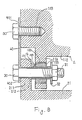
- An absorbing unit 12 includes inside ring spacer 121, outside ring spacer 122 and cylindrical elastic member 123 made of elastic materials, such as a vibroisolating rubber.
- the length of inside ring spacer 121 is longer than that of the outside ring spacer 122.
- the elastic member 123 is attached on the outer surface of inside ring spacer 121 by adhesively vulcanizing and the outside ring spacer 122 is also affixed on the outer surface of elastic member 123 by vulcanizing adhesively.
- Compressor 21 has a plurality of flanges 211 radially outwardly projecting from both end portion of housing of compressor 21. A hole 212 is formed through each flanges 211.
- Coupling plates 40 which have holes 401,402 at their both ends, respectively, is connected between mount bracket 11 and compressor 21. That is, each coupling plate 40 is fixed on one end surface of mount bracket 11 by screwing bolt 50. The other end of coupling plate 40 is fixed on the outer end surface of flanges 211 of compressor 21 by screwing bolt 30 and nut 31, Coupling plate 40 is made of high strength materials, such as stainless steel or aluminum, and has characteristic for being able to bend in the axial direction of compressor 21.
- compressor 21 if engine 1 starts driving power is transmitted from engine 1 to compressor 21 through belt 4, and compressor 21 is thus driven.
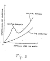
- compressor 21 since compressor 21 and mount bracket 11 are securely connected by coupling plate 40, which is made of materials with high strength, engine 1 and compressor 21 moves together according to the condition of the mechanical radial vibration of engine 1. Therefore, resonance between engine 1 and compressor 21 is prevented from being produced as shown in Fig. 5, and the durability of the elastic member 123 is improved.
- belt 4 is hung on pulleys 2,3, deformation of elastic member 123 and lack of tension of belt 4 is also prevented from being produced. Still furthermore, compressor 21 is earthed through coupling plate 40.
- the coupling plate may be formed as flat plate shape.
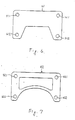
- Coupling plate 41 has two pair of holes 411, 412 and is scooped at its bottom end to be lightweight. Holes 412 of coupling plate 41 are preformed at the location corresponding to holes 112 of flanges 111 of mount bracket 11 when one end of coupling plate 41 is fixed on one end surface of mount bracket 11 by screwing bolts 50. Therefore, the location of the holes 412 of the coupling plate 41 relatively to the holes 112 of the flanges 112 are easily made. If the coupling plate should be more reduced in the weight, the central portion of plate 42 can be scooped, as shown in Fig. 7.
- Absorbing unit 13 includes inside ring spacer 131, outside ring spacer 132 and ring plate 134 covered by elastic member 133.
- Elastic member 133 is made of elastic materials, such as a vibroisolating rubber.
- Inside ring spacer 131, outside ring spacer 132 and ring plate 134 are made of materials with high strength, such as metals.
- Elastic member 133 which includes ring plate 134 is affixed on the outer surface of inside ring spacer 131 by vulcanizing adhesively and, the outside ring spacer 132 is also affixed on the outer surface of elastic member 133.
- Ring 134 is formed so that the outer surface contacts the inner surface of outside ring spacer 132 and the inner surface of ring 134 contacts the outer surface of inside ring spacer 131.
- Absorbing unit 13 is fixedly disposed in holes 212 of flanges 211 of compressor 21 by vulcanizing adhesive. Bolts 30 pass through the absorbing unit 13 and holes 112 of flanges 111 of mount bracket 11 to fixed compressor 21 on mount bracket 11. In this construction, since ring 134 may accomplish the same function as coupling plate 40 as mentioned in the above embodiments, coupling plate 40 is not necessary.
- Absorbing unit 14 includes inside ring spacer 141, outside ring spacer 142 and ring plate 144a which is covered by elastic member 143 therebetween.
- Ring plate 144 has scooped portions 144a with a regular interval therebetween along with the outer and inner circumferences thereof. Therefore, ring plate 144 partly contacts the outer surface of inside ring spacer 141 and the inner surface of outside ring spacer 141 under the condition of line-contact.
- scooped portions 144a are formed along with the outer and inner circumferences of ring 144, absorbing assembly 14 may be easily bent axially.
- Ring plate 145 may be provided with many small scooped portions 145a with a regular interval therebetween along with the outer and inner circumferences thereof, as shown in Fig. 10(c).
- each fiber bits 154 is made of materials with high strength, for example, metal, carbon and hard plastics, and disposed with a axial and radial regular interval between inside ring spacer 151 and outside ring spacer 152.
- the outer end surface of fiber bit 154 thus contacts the inner surface of outside ring spacer 152 and the inner end surface of fiber bit 154 contacts the outer surface of inside ring spacer 151. That is, each metal bit 154 is identical to the other. Therefore, in this embodiment, absorbing assembly 15 may be more easily bent axially.
- the ring plate could be replaced with a plurality of spherical members 164, which are covered by elastic member 163.
- Each spherical members 164 is disposed with a regular interval along with a circumference of inside ring spacer 161.
- the diameter of each spherical members 164 equals the radial gap between the outer surface of inside ring spacer 161 and the inner surface of outside ring spacer 162 so that spherical member 164 can receive radial force. Therefore, the outer surface of spherical members 164 contact those surfaces under the condition of point-contact.
- an oval member can be used under the condition that the end surfaces of the oval member at the side of ring diameter contact the inner surface of outside ring spacer and the outer surface of inside ring spacer, respectively.
Landscapes
- Engineering & Computer Science (AREA)
- General Engineering & Computer Science (AREA)
- Mechanical Engineering (AREA)
- Physics & Mathematics (AREA)
- Chemical & Material Sciences (AREA)
- Combustion & Propulsion (AREA)
- Acoustics & Sound (AREA)
- Aviation & Aerospace Engineering (AREA)
- Thermal Sciences (AREA)
- Vibration Prevention Devices (AREA)
- Air-Conditioning For Vehicles (AREA)
- Compressor (AREA)
Applications Claiming Priority (4)
| Application Number | Priority Date | Filing Date | Title |
|---|---|---|---|
| JP15907486U JPH0313596Y2 (de) | 1986-10-17 | 1986-10-17 | |
| JP159074/86U | 1986-10-17 | ||
| JP19302086U JPH0313594Y2 (de) | 1986-12-17 | 1986-12-17 | |
| JP193020/86U | 1986-12-17 |
Publications (3)
| Publication Number | Publication Date |
|---|---|
| EP0264833A2 true EP0264833A2 (de) | 1988-04-27 |
| EP0264833A3 EP0264833A3 (en) | 1989-02-08 |
| EP0264833B1 EP0264833B1 (de) | 1991-03-20 |
Family
ID=26485986
Family Applications (1)
| Application Number | Title | Priority Date | Filing Date |
|---|---|---|---|
| EP87115098A Expired - Lifetime EP0264833B1 (de) | 1986-10-17 | 1987-10-15 | Montierungsmechanismus für den Kompressor einer Fahrzeugklimaanlage |
Country Status (5)
| Country | Link |
|---|---|
| US (2) | US4834336A (de) |
| EP (1) | EP0264833B1 (de) |
| KR (1) | KR950000784B1 (de) |
| AU (2) | AU594515B2 (de) |
| DE (1) | DE3768755D1 (de) |
Cited By (6)
| Publication number | Priority date | Publication date | Assignee | Title |
|---|---|---|---|---|
| EP0307851A3 (en) * | 1987-09-14 | 1990-03-14 | Sanden Corporation | Mounting mechanism for an automotive air conditioning compressor |
| EP0359100A1 (de) * | 1988-09-13 | 1990-03-21 | Sanden Corporation | Kompressorgehäuse mit einer Struktur, die das Gleiten der schwingungsisolierenden Teile verhindert |
| EP0339682A3 (en) * | 1988-04-28 | 1990-09-12 | Sanden Corporation | Mounting mechanism for an automotive air conditioning compressor |
| EP0353091A3 (de) * | 1988-07-29 | 1990-11-28 | Sanden Corporation | Schwingungsdämpfungsmechanismus für einen Kompressor einer Fahrzeugklimaanlage |
| FR2660383A1 (fr) * | 1990-04-02 | 1991-10-04 | Hutchinson Sa | Support elastique, notamment pour suspension de vehicule automobile, a rigidites fortement differenciees. |
| EP2390503A1 (de) * | 2010-05-26 | 2011-11-30 | Valeo Thermal Systems Japan Corporation | Verdichter für Fahrzeugklimaanlagen |
Families Citing this family (24)
| Publication number | Priority date | Publication date | Assignee | Title |
|---|---|---|---|---|
| FR2624218B1 (fr) * | 1987-12-07 | 1990-04-13 | Peugeot | Dispositif de fixation d'une premiere piece telle qu'accessoire a une deuxieme piece telle que support a douille de rattrapage du jeu d'assemblage entre les deux pieces et douille utilisee pour la fixation de ces pieces |
| US5007807A (en) * | 1989-03-08 | 1991-04-16 | Tecumseh Products Company | Hermetic compressor having resilient internal mounting |
| US5295414A (en) * | 1991-04-15 | 1994-03-22 | Kubota Corporation | Vibration and noise proofing system for a hydrostatic stepless transmission attached to a transmission case |
| US5335893A (en) * | 1992-10-23 | 1994-08-09 | The Boeing Company | 360 degree adjustable vibration dampening and thermal isolating bracket |
| US5306121A (en) * | 1993-04-23 | 1994-04-26 | Carrier Corporation | Compressor tiered mounting arrangement |
| US5699677A (en) * | 1996-11-07 | 1997-12-23 | White Consolidated Industries, Inc. | Compressor mounted drain pan utilizing polyurethane adhesive |
| US6431189B1 (en) | 1997-06-02 | 2002-08-13 | 700303 Alberta Ltd. | Apparatus for and method of disinfecting hands |
| DE19733478B4 (de) * | 1997-08-02 | 2006-03-23 | Daimlerchrysler Ag | Schwingungsdämpfer für eine rohrförmige Gelenkwelle |
| JP3880158B2 (ja) * | 1997-10-21 | 2007-02-14 | カルソニックカンセイ株式会社 | 斜板式圧縮機 |
| FR2781849B1 (fr) * | 1998-07-28 | 2000-09-29 | Hutchinson | Dispositif a rattrapage de jeu pour fixation d'une piece |
| JP2000234586A (ja) * | 1998-12-17 | 2000-08-29 | Denso Corp | 電動圧縮機の取付構造 |
| DE19914655A1 (de) * | 1999-03-31 | 2000-10-12 | Luk Fahrzeug Hydraulik | CO¶2¶-Kompressor |
| US6374939B1 (en) * | 2000-06-19 | 2002-04-23 | General Motors Corporation | Engine mount assembly |
| JP2002276554A (ja) * | 2001-03-14 | 2002-09-25 | Matsushita Electric Ind Co Ltd | 移動車のエンジンに搭載される電動機内蔵の圧縮機 |
| US6705581B2 (en) | 2001-05-26 | 2004-03-16 | Pacsci Motion Control, Inc. | Pivotable motor mounting apparatus |
| DE102009055107B4 (de) * | 2009-12-21 | 2017-12-07 | Hanon Systems | Befestigungsanordnung eines Kältemittelverdichters |
| JP5482387B2 (ja) * | 2010-03-31 | 2014-05-07 | 株式会社豊田自動織機 | 電動圧縮機 |
| JP5273084B2 (ja) * | 2010-03-31 | 2013-08-28 | 株式会社豊田自動織機 | 電動圧縮機 |
| JP5556721B2 (ja) * | 2011-03-28 | 2014-07-23 | 株式会社豊田自動織機 | 電動圧縮機 |
| US9696061B2 (en) * | 2014-10-21 | 2017-07-04 | Haier Us Appliance Solutions, Inc. | Heat pump water heater appliance |
| CN107225932A (zh) * | 2017-06-12 | 2017-10-03 | 奇瑞汽车股份有限公司 | 一种汽车空调压缩机安装支架及安装结构 |
| US11092206B2 (en) * | 2017-10-02 | 2021-08-17 | Ford Global Technologies, Llc | Electrically conductive mechanical vibration isolator |
| CN108826525B (zh) * | 2018-07-06 | 2024-01-30 | 太仓京和机电有限公司 | 车用空调外机 |
| CN116803716B (zh) * | 2023-02-03 | 2026-01-16 | 浙江三花智能控制股份有限公司 | 热管理集成模块 |
Family Cites Families (19)
| Publication number | Priority date | Publication date | Assignee | Title |
|---|---|---|---|---|
| USRE18457E (en) * | 1927-01-10 | 1932-05-10 | Vibeation dampening mounting | |
| US1862483A (en) * | 1930-06-23 | 1932-06-07 | Hugh C Lord | Automobile engine mounting |
| US2212142A (en) * | 1936-08-05 | 1940-08-20 | Crown Cork & Seal Co | Vibration absorbing supporting structure |
| US2540767A (en) * | 1945-06-29 | 1951-02-06 | Paul C Tabbert | Rotary pump |
| US2901195A (en) * | 1955-08-03 | 1959-08-25 | Continental Can Co | Motor mounting means |
| DE1400311A1 (de) * | 1960-02-12 | 1968-10-10 | ||
| US3057218A (en) * | 1960-02-19 | 1962-10-09 | Borg Warner | Drive assembly |
| US3274394A (en) * | 1964-07-24 | 1966-09-20 | Roland R Maheu | Alternator mounting assembly for vehicles |
| US3476309A (en) * | 1968-04-19 | 1969-11-04 | Borg Warner | Mounting arrangement for rotary compressor |
| US3494540A (en) * | 1969-04-28 | 1970-02-10 | Don P Dixon | Automobile air conditioning system |
| US3813776A (en) * | 1973-05-15 | 1974-06-04 | Mccullough Corp | Vibration isolation system particularly adapted for use with a chain saw |
| FR2291406A1 (fr) * | 1974-11-15 | 1976-06-11 | Messier Hispano Sa | Element de palier de guidage sans frottement pour mouvements rectilignes de faible course |
| JPS6136819Y2 (de) * | 1980-07-23 | 1986-10-25 | ||
| JPS5761252A (en) * | 1980-09-05 | 1982-04-13 | Toshiba Corp | Rotating anode for x-ray tube |
| JPS5760820U (de) * | 1980-09-12 | 1982-04-10 | ||
| JPS5783790A (en) * | 1980-11-10 | 1982-05-25 | Sankyo Denki Co Ltd | Compressor for cooling vehicles |
| JPS59164428A (ja) * | 1983-03-09 | 1984-09-17 | Tokai Rubber Ind Ltd | 流体入りブツシユ |
| ZA846202B (en) * | 1983-08-10 | 1985-04-24 | Ayr Pty Ltd | Alternator mounting assembly |
| US4901787A (en) * | 1988-08-04 | 1990-02-20 | Balanced Engines, Inc. | Regenerative heat exchanger and system |
-
1987
- 1987-10-15 EP EP87115098A patent/EP0264833B1/de not_active Expired - Lifetime
- 1987-10-15 DE DE8787115098T patent/DE3768755D1/de not_active Expired - Lifetime
- 1987-10-17 KR KR1019870011590A patent/KR950000784B1/ko not_active Expired - Fee Related
- 1987-10-19 AU AU79905/87A patent/AU594515B2/en not_active Ceased
- 1987-10-19 US US07/109,863 patent/US4834336A/en not_active Expired - Fee Related
-
1989
- 1989-02-22 US US07/313,503 patent/US4988071A/en not_active Expired - Fee Related
- 1989-12-12 AU AU46138/89A patent/AU616086B2/en not_active Ceased
Cited By (8)
| Publication number | Priority date | Publication date | Assignee | Title |
|---|---|---|---|---|
| EP0307851A3 (en) * | 1987-09-14 | 1990-03-14 | Sanden Corporation | Mounting mechanism for an automotive air conditioning compressor |
| EP0339682A3 (en) * | 1988-04-28 | 1990-09-12 | Sanden Corporation | Mounting mechanism for an automotive air conditioning compressor |
| AU624606B2 (en) * | 1988-04-28 | 1992-06-18 | Sanden Corporation | Mounting mechanism for an automotive air conditioning compressor |
| EP0353091A3 (de) * | 1988-07-29 | 1990-11-28 | Sanden Corporation | Schwingungsdämpfungsmechanismus für einen Kompressor einer Fahrzeugklimaanlage |
| EP0359100A1 (de) * | 1988-09-13 | 1990-03-21 | Sanden Corporation | Kompressorgehäuse mit einer Struktur, die das Gleiten der schwingungsisolierenden Teile verhindert |
| US5145330A (en) * | 1988-09-13 | 1992-09-08 | Sanden Corporation | Compressor housing having a structure for preventing the slippage of vibroisolating members |
| FR2660383A1 (fr) * | 1990-04-02 | 1991-10-04 | Hutchinson Sa | Support elastique, notamment pour suspension de vehicule automobile, a rigidites fortement differenciees. |
| EP2390503A1 (de) * | 2010-05-26 | 2011-11-30 | Valeo Thermal Systems Japan Corporation | Verdichter für Fahrzeugklimaanlagen |
Also Published As
| Publication number | Publication date |
|---|---|
| US4988071A (en) | 1991-01-29 |
| KR880004967A (ko) | 1988-06-27 |
| US4834336A (en) | 1989-05-30 |
| AU616086B2 (en) | 1991-10-17 |
| AU594515B2 (en) | 1990-03-08 |
| EP0264833A3 (en) | 1989-02-08 |
| AU7990587A (en) | 1988-04-21 |
| EP0264833B1 (de) | 1991-03-20 |
| KR950000784B1 (ko) | 1995-02-02 |
| DE3768755D1 (de) | 1991-04-25 |
| AU4613889A (en) | 1990-03-29 |
Similar Documents
| Publication | Publication Date | Title |
|---|---|---|
| EP0264833A2 (de) | Montierungsmechanismus für den Kompressor einer Fahrzeugklimaanlage | |
| EP0339682B1 (de) | Lagerungsmechanismus für den Kompressor einer Fahrzeugklimaanlage | |
| JP3503405B2 (ja) | 防振装置 | |
| KR950003703B1 (ko) | 자동차 공기조화기의 압축기 장착기구 | |
| EP0584400B1 (de) | Wellenkupplung | |
| EP0903511A2 (de) | Biegsame Platte und Schwungradgestaltung | |
| US4860867A (en) | Electromagnetic clutch | |
| EP0717211B1 (de) | Biegsame Platte zur Drehmomentübertragung | |
| EP0469747B1 (de) | Lagerisolator | |
| EP0856684A1 (de) | Riemenspanner | |
| JP3160165B2 (ja) | 車両用ドライブプレート | |
| CA1294229C (en) | Electromagnetic clutch | |
| US4971595A (en) | Sliding universal joint having a holder inclination restriction flange and independent rails | |
| EP0653315A1 (de) | Radnabeeinrichtung mit Lagervorrichtung und homokinetischer Kupplung | |
| US6626763B2 (en) | Drive shaft | |
| EP0339431B1 (de) | Elektromagnetisch betätigte Kupplung | |
| US7025187B2 (en) | Electromagnetic clutch assembly | |
| CN219788393U (zh) | 机器人关节及机器人 | |
| WO2007119915A1 (en) | Motor assembly | |
| KR20000068947A (ko) | 와이퍼 시스템 | |
| EP1191668B1 (de) | Motorlagerung zum schwingungsdämpfenden Lagern eines Elektromotors | |
| JPH0379204B2 (de) | ||
| JPH0740102Y2 (ja) | フレキシブルカップリング | |
| JPH01218915A (ja) | 車輛用空調装置の圧縮機取付機構 | |
| JPS6398490U (de) |
Legal Events
| Date | Code | Title | Description |
|---|---|---|---|
| PUAI | Public reference made under article 153(3) epc to a published international application that has entered the european phase |
Free format text: ORIGINAL CODE: 0009012 |
|
| AK | Designated contracting states |
Kind code of ref document: A2 Designated state(s): AT BE CH DE ES FR GB GR IT LI LU NL SE |
|
| RBV | Designated contracting states (corrected) |
Designated state(s): DE FR GB IT SE |
|
| PUAL | Search report despatched |
Free format text: ORIGINAL CODE: 0009013 |
|
| AK | Designated contracting states |
Kind code of ref document: A3 Designated state(s): DE FR GB IT SE |
|
| 17P | Request for examination filed |
Effective date: 19890413 |
|
| 17Q | First examination report despatched |
Effective date: 19890912 |
|
| ITF | It: translation for a ep patent filed | ||
| GRAA | (expected) grant |
Free format text: ORIGINAL CODE: 0009210 |
|
| RAP1 | Party data changed (applicant data changed or rights of an application transferred) |
Owner name: SANDEN CORPORATION |
|
| AK | Designated contracting states |
Kind code of ref document: B1 Designated state(s): DE FR GB IT SE |
|
| REF | Corresponds to: |
Ref document number: 3768755 Country of ref document: DE Date of ref document: 19910425 |
|
| ET | Fr: translation filed | ||
| PLBE | No opposition filed within time limit |
Free format text: ORIGINAL CODE: 0009261 |
|
| STAA | Information on the status of an ep patent application or granted ep patent |
Free format text: STATUS: NO OPPOSITION FILED WITHIN TIME LIMIT |
|
| 26N | No opposition filed | ||
| EAL | Se: european patent in force in sweden |
Ref document number: 87115098.3 |
|
| PGFP | Annual fee paid to national office [announced via postgrant information from national office to epo] |
Ref country code: SE Payment date: 19981006 Year of fee payment: 12 |
|
| PGFP | Annual fee paid to national office [announced via postgrant information from national office to epo] |
Ref country code: FR Payment date: 19981009 Year of fee payment: 12 |
|
| PGFP | Annual fee paid to national office [announced via postgrant information from national office to epo] |
Ref country code: GB Payment date: 19981016 Year of fee payment: 12 |
|
| PGFP | Annual fee paid to national office [announced via postgrant information from national office to epo] |
Ref country code: DE Payment date: 19981023 Year of fee payment: 12 |
|
| PG25 | Lapsed in a contracting state [announced via postgrant information from national office to epo] |
Ref country code: GB Free format text: LAPSE BECAUSE OF NON-PAYMENT OF DUE FEES Effective date: 19991015 |
|
| PG25 | Lapsed in a contracting state [announced via postgrant information from national office to epo] |
Ref country code: SE Free format text: THE PATENT HAS BEEN ANNULLED BY A DECISION OF A NATIONAL AUTHORITY Effective date: 19991030 |
|
| GBPC | Gb: european patent ceased through non-payment of renewal fee |
Effective date: 19991015 |
|
| EUG | Se: european patent has lapsed |
Ref document number: 87115098.3 |
|
| PG25 | Lapsed in a contracting state [announced via postgrant information from national office to epo] |
Ref country code: FR Free format text: LAPSE BECAUSE OF NON-PAYMENT OF DUE FEES Effective date: 20000630 |
|
| PG25 | Lapsed in a contracting state [announced via postgrant information from national office to epo] |
Ref country code: DE Free format text: LAPSE BECAUSE OF NON-PAYMENT OF DUE FEES Effective date: 20000801 |
|
| REG | Reference to a national code |
Ref country code: FR Ref legal event code: ST |
|
| PG25 | Lapsed in a contracting state [announced via postgrant information from national office to epo] |
Ref country code: IT Free format text: LAPSE BECAUSE OF NON-PAYMENT OF DUE FEES;WARNING: LAPSES OF ITALIAN PATENTS WITH EFFECTIVE DATE BEFORE 2007 MAY HAVE OCCURRED AT ANY TIME BEFORE 2007. THE CORRECT EFFECTIVE DATE MAY BE DIFFERENT FROM THE ONE RECORDED. Effective date: 20051015 |