EP0264856A2 - Appareil pour couper un afflux de gaz - Google Patents
Appareil pour couper un afflux de gaz Download PDFInfo
- Publication number
- EP0264856A2 EP0264856A2 EP87115173A EP87115173A EP0264856A2 EP 0264856 A2 EP0264856 A2 EP 0264856A2 EP 87115173 A EP87115173 A EP 87115173A EP 87115173 A EP87115173 A EP 87115173A EP 0264856 A2 EP0264856 A2 EP 0264856A2
- Authority
- EP
- European Patent Office
- Prior art keywords
- gas
- consumption
- flow rate
- shutoff
- signal
- Prior art date
- Legal status (The legal status is an assumption and is not a legal conclusion. Google has not performed a legal analysis and makes no representation as to the accuracy of the status listed.)
- Granted
Links
Images


Classifications
-
- G—PHYSICS
- G01—MEASURING; TESTING
- G01F—MEASURING VOLUME, VOLUME FLOW, MASS FLOW OR LIQUID LEVEL; METERING BY VOLUME
- G01F15/00—Details of, or accessories for, apparatus of groups G01F1/00 - G01F13/00 insofar as such details or appliances are not adapted to particular types of such apparatus
- G01F15/001—Means for regulating or setting the meter for a predetermined quantity
- G01F15/002—Means for regulating or setting the meter for a predetermined quantity for gases
-
- F—MECHANICAL ENGINEERING; LIGHTING; HEATING; WEAPONS; BLASTING
- F23—COMBUSTION APPARATUS; COMBUSTION PROCESSES
- F23N—REGULATING OR CONTROLLING COMBUSTION
- F23N5/00—Systems for controlling combustion
- F23N5/18—Systems for controlling combustion using detectors sensitive to rate of flow of air or fuel
- F23N5/184—Systems for controlling combustion using detectors sensitive to rate of flow of air or fuel using electronic means
-
- G—PHYSICS
- G04—HOROLOGY
- G04F—TIME-INTERVAL MEASURING
- G04F1/00—Apparatus which can be set and started to measure-off predetermined or adjustably-fixed time intervals without driving mechanisms, e.g. egg timers
-
- G—PHYSICS
- G08—SIGNALLING
- G08B—SIGNALLING SYSTEMS, e.g. PERSONAL CALLING SYSTEMS; ORDER TELEGRAPHS; ALARM SYSTEMS
- G08B17/00—Fire alarms; Alarms responsive to explosion
- G08B17/10—Actuation by presence of smoke or gases, e.g. automatic alarm devices for analysing flowing fluid materials by the use of optical means
- G08B17/117—Actuation by presence of smoke or gases, e.g. automatic alarm devices for analysing flowing fluid materials by the use of optical means by using a detection device for specific gases, e.g. combustion products, produced by the fire
-
- F—MECHANICAL ENGINEERING; LIGHTING; HEATING; WEAPONS; BLASTING
- F23—COMBUSTION APPARATUS; COMBUSTION PROCESSES
- F23N—REGULATING OR CONTROLLING COMBUSTION
- F23N5/00—Systems for controlling combustion
- F23N5/18—Systems for controlling combustion using detectors sensitive to rate of flow of air or fuel
-
- F—MECHANICAL ENGINEERING; LIGHTING; HEATING; WEAPONS; BLASTING
- F23—COMBUSTION APPARATUS; COMBUSTION PROCESSES
- F23N—REGULATING OR CONTROLLING COMBUSTION
- F23N5/00—Systems for controlling combustion
- F23N5/20—Systems for controlling combustion with a time program acting through electrical means, e.g. using time-delay relays
-
- Y—GENERAL TAGGING OF NEW TECHNOLOGICAL DEVELOPMENTS; GENERAL TAGGING OF CROSS-SECTIONAL TECHNOLOGIES SPANNING OVER SEVERAL SECTIONS OF THE IPC; TECHNICAL SUBJECTS COVERED BY FORMER USPC CROSS-REFERENCE ART COLLECTIONS [XRACs] AND DIGESTS
- Y10—TECHNICAL SUBJECTS COVERED BY FORMER USPC
- Y10T—TECHNICAL SUBJECTS COVERED BY FORMER US CLASSIFICATION
- Y10T137/00—Fluid handling
- Y10T137/8593—Systems
- Y10T137/86389—Programmer or timer
Definitions
- the present invention relates generally to a gas shutoff apparatus for a gas equipment using a town gas or liquefied petroleum gas, and more particularly to a gas shutoff apparatus for preventing gas explosion or gas poisoning due to a gas escape from a gas supply tube or gas equipment.
- the greater part of gas accidents are caused by escape of an unburned gas such as town gas or liquefied petroleum gas (hereinafter is referred to as the gas).
- the gas escapes when a main cock for supplying the gas to a gas equipment is opened without burning of the gas, when unexpected disconnection of a rubber tube supplying the gas to the gas equipment occurs or the rubber tube has cracks thereon and the like.
- an automatic shutoff valve, a reinforced tube, an alarm to detect the escaped gas and an automatic gas shutoff system which is connected to the alarm are, etc., used.
- the automatic shutoff valve usually cannot be activated under a small flow rate of the escaping gas, and the escape of the gas cannot be interrupted.
- the gas alarm it only generates an alarm, therefore if a person is absent from there or fails to notice it, the main cock cannot be shut, and dangerous escape of the gas cannot be interrupted.
- diffusion thereof to existing houses is difficult owing to its high cost and necessity of connecting construction.
- the above-mentioned conventional contermeasures are not effective to gas suicide which is liable to cause gas explosion.
- a gas shutoff apparatus for preventing the gas explosion or gas suicide is manufactured.
- a flow rate of the gas is detected, and constant and continuous flow of a lot of gas for a long time is recognized as an abnormal state by a microcomputer, for example.
- gas meters having predetermined reference values of the flow rate and/or use time it is important to select an appropriate gas meter having suitable reference values for the consumers among a number of gas meters of different characteristics, in installing the gas meter. If a gas meter of under-capacity is selected, wherein the reference values are smaller for that consumer, gas is liable to be uselessly interrupted though usage is in normal flow rate. On the contrary, if a gas meter of over-capacity of the reference values is installed, wherein the respective reference values are larger than suitable reference values for the consumer, the gas is liable to fail to be interrupted even when the interruption of the gas is required. Therefore, there is a grove problem in safety aspect.
- An object of the present invention is to provide a gas shutoff apparatus which is adaptable to various consumers of a town gas or liquefied petorleum gas.
- the gas shutoff apparatus in accordance with the present invention, when a flow rate of the gas during an operation of the timer exceeds the maximum value memorized in advance, data in the consumption-state memory is rewritten. Furthermore, when the operation of the timer has finished, the reference value of the flow rate is changed to a new reference value corresponding to the maximum value of a flow rate memorized in the consumption-state memory. In the similar manner, the reference value of the use time period is changed to a value corresponding to data obtained in the time period of the timer.
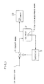
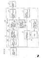
- FIG.1 is a block diagram showing a principle of a constitution of a gas shutoff apparatus in accordance with the present invention.
- a gas equipment 33 such as a gas range or gas heater is connected to a gas supply tube 1 through a shutoff means 4 and a gas meter 2 containing flow rate measurement means 3 such as a belows type digital gas flow rate meter therein.
- the shutoff means such as known electromagnetic gas shutoff valve 4 is disposed between the gas supply tube 1 and the gas meter 2, and is controlled by a controller 5 such as an electronic circuit or a microcomputer receiving a flow rate signal from the flow rate measurement means 3.
- a normal condition decision means of gas consumption 8 which is e.g. a comparator or value comparation step of microcomputer outputs a shutoff signal by decision of abnormal condition when an output signal of the consumption state detection means 6 deviates from the normal condition of gas consumption.
- a timer 9 measures a predetermined time period by a starting signal from a starting signal generating means 10.
- a consumption-state memory 11 memorizes the consumption state on the basis of the flow rate signal from the flow rate measurement means 3 during an operating period of the timer 9.
- the varying means 12 of normal condition of gas consumption varies the normal condition of gas consumption set therein corresponding to data of the consumption-state memory 11.
- a shutoff signal output means 13 outputs a closing signal for closing to the shutoff means 4 on the basis of a shutoff signal from the normal condition decision means of gas consumption 8.
- the timer 9 When the timer 9 receives a starting signal by operation of the starting signal generating means 10, for example a push-button switch or an input signal from an outer device (not shown), the timer 9 starts measurement of a time period.
- the timer period is selected two weeks or one month, for example.
- an amount of the gas consumption, maximum flow rates of the respective gas equipments and a continuous time of the gas consumption which are measured by the flowrate signal of the flow rate measurement means 3 are memorized in the consumption-state memory 11 from start of the timer 9.
- a combination of the amount of gas consumption, the maximum flow rates and the continuous consumption time is commonly called as "a gas consumption pattern".
- Memorized data in the consumption-state memory 11 gives the gas consumption pattern.
- FIG.4(a) and FIG.4(b) show a flow chart of the microcomputer 14.
- the flow rate is measured by the flow rate measurement means 3 (Step A).
- the consumption state is detected by the consumption state detection means 6 (Step B).
- Operation of the timer 9 is examined by the starting signal generating means 10 (Step C).
- the consumption state is memorized in the consumption-state memory 11, and the consumption state is replaced with a new maximum consumption state (Step E).
- the starting signal generating means 10 is not operated and the timer 9 is also out of operation, the consumption state detected by the consumption state detection means 6 is compared with the normal condition of gas consumption in the normal condition decision means of gas consumption 8 (Step D).
- Step F and G a closing signal is output from the closing signal output means 13
- Step H the operation of the program is returned to the Step A, and measurement of the flow rate is repeated.
- the varying means 12 of normal condition of gas consumption is not operated in the normal condition of the gas consumption, when the counting operation of the timer 9 finished, the varying means 12 of normal condition of gas consumption is operated (Steps I and J).
- the maximum values of the consumption state are multiplied by a predetermined safety factor in an actual apparatus.
- Step D a consumption state detected by the consumption state detection means 6 is compared with the modified new normal condition of gas consumption. Then, finish of the counting operation of the counter 9 is examined (Step L).
- Step N input of a starting signal is examined (Step N).
- the time counting operation of the timer 9 is started by input of the starting signal (Step O). When the starting signal is not inputted, the flow of the flow chart is returned to the Step A.
- FIG.5 is a timing chart showing the operation of the timer 9.
- abscissa is graduated by time
- the ordinate is graduated by the normal condition of gas consumption.
- a starting signal is inputted to the timer 9 at a time t S , and a counting operation starts. Then, the counting operation finishes at a time t E .
- the gas consumption pattern is observed in the time period from the time t S to time t E as shown by hatching.
- the initial condition set in the initial condition setting means 7 is referred as a reference value until the time t E .
- the normal condition of gas consumption is renewed in the varying means 12 of normal condition of gas consumption.
- the technical advantages of the embodiment in accordance with the present invention are mentioned below.
- the consumption state is always monitored and is compared with the normal condition of gas consumption. Therefore, when the consumption state deviates from the normal condition of gas consumption by escape of the gas or forgetting extinction of a gas stove, for example, supply of the gas is interrupted by the operation of the shutoff means. As a result, gas explosion or gas poisoning can be prevented in a preliminary stage. Furthermore, since an actual gas consumption pattern of a consumer is observed during a predetermined time period, and the consumption state is renewed by the observation data, a specific gas consumption pattern of the consumer is introduced into the gas shutoff apparatus. And safety in use of a gas equipment is further improved.
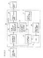
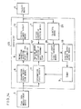
- FIG.6 is a block diagram of a second embodiment of the present invention.
- a consumption state detection means 6 further comprises a rank discriminator 18 and a continuous operation time measurement means 19 for measuring time of nonstop operation of a gas equipment.
- a range of flow rates of the gas is divided into plural ranks, and the rank of a flow rate is decided by the rank discriminator 18.
- the continuous operation times with respect to the respective ranks of flow rate are measured by the continuous operation time measurement means 19.
- Respective allowable times for continuous operation with respect to the respective ranks of flow rate are set in the initial condition setting means 7 as initial conditions.
- a maximum value of the continuous operation times of the respective ranks of flow rate during operation of the timer 9 are memorized in the consumption-state memory 11.
- the maximum value of the respective continuous operation times with respect to the respective ranks of flow rate memorized in the consumption-state memory 11 are given to the continuous operation time measurement means 19 as data.
- the data of the respective ranks of the flow rate are compared with the respective allowable time set in the initial condition setting means 7, and either shorter times in respective ranks of flow rate are elected in the continuous operation time measurement means 19.
- the resultant continuous operation times elected as mentioned above are set in the continuous operation time measurement means 19, as new total operation times with respect to the respective ranks of flow rate. Thereafter, signal from the rank discriminator 18 is decided on the basis of the new continuous operation time.
- the continuous operation time can be multiplied by a predetermined safety factor.
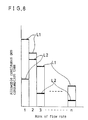
- FIG.8 is a graph showing the allowable continuous gas consumption time periods with regard to the respective ranks of flow rate. Referring to FIG.8, ranks of flow rate are graduated on the abscissa and allowable continuous gas consumption time periods are graduated on ordinate. Horizontal lines L1 show the allowable continuous gas consumption time periods set in the initial condition setting means 7. Horizontal lines L2 show new allowable continuous gas consumption time periods, which are renewed in the varying means 12 of normal condition of gas consumption.
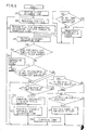
- Step I When the continuous gas consumption time period is under the allowable continuous gas consumption time period (normal state), operation of the varying means 12 of normal condition of gas consumption is examined (Step I). If the operation is finished, the step of the operation return to the Step B. If the operation of the varying means 12 of normal condition of gas consumption does not finish, finish of the counting operation of the timer 9 is examined (Step J). When the counting operation of the timer 9 has finished, the gas consumption is compared with the initial condition set the initial condition setting means 7 (Step K), and the allowable continuous gas consumption time period is refreshed (Step L). After then, the value of allowable continuous gas consumption time period which has been set in the Step L is used in the next successive continuous gas consumption time measurement in Step F.
- Step of the flow chart returns to the Step B during the while the timer continues counting operation (Steps J and M). If the timer 9 is not making counting operation, input of a starting signal is examined (Step O). When the starting signal is inputted, the timer 9 starts counting operation (Step P). Meanwhile, the step returns to Step B in the absence of the starting signal.
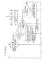
- shutoff means 4 when the shutoff means 4 is operated during counting operation of the timer 9, count of the timer 9 is cleared and operation of the consumption-state memory 11 is interrupted by the signal from the shutoff-means-reset-signal-detector 22.
- the signal also acts to start the timer 9 like the starting signal of the starting signal generating means 10.
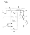
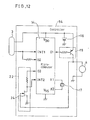
- FIG.12 is a detailed circuitry of the controller 54 as shown in FIG.11. Referring to FIG.12, means having the same reference numerals as shown in FIG.3 are identical with what is shown in FIG.3.
- the shutoff-means-reset-signal-detector 22 comprises a resistor and an N-channel FET 24.
- a shutoff device having a permanent magnet, a magnetic coil and a spring for holding its opening state are used as the shutoff means 4, for example. In the shutoff operation of the shutoff device, an electric pulse is applied to the magnetic coil so as to generate a magnetic force having reverse magnetic pole to that of the permanent magnet. Then, the shutoff state of the shutoff device is held by the force of the spring.
- Reopening of the shutoff device is accomplished by manual operation, for example.
- a counter electromotive force is generated in the magnetic coil, and an electric potential owing to the counter electromotive force is applied to the gate of the conjunction type N-channel FET 24 of the shutoff-means-reset-signal-detector 22.
- the FET 24 is in OFF state during the while the electric potential is smaller than the cutoff voltage of the N-channel FET 24.
- an input voltage is applied to the input terminal INT 2 of the microcomputer 14, since electric potential of the output terminal 03 of the microcomputer 14 is at high level.
- FIG.13(a), FIG.13(b) and FIG.13(c) show a flow chart showing an operation of the controller 54 as shown in FIG.11. Description of the steps which are identical with what is made on FIG.4 is omitted.
- Step S input of the reset signal is examined (Step S) and, when the reset signal is not exist the gas consumption is examined (Step U).
- flow in the gas supply tube 1 is closed by operation of the shutoff means 4 (Step G).
- the shutoff signal is issued again (Step G).
- input of the reset signal is monitored (Step S).
- Step T input of the reset signal
- Step T input of the reset signal
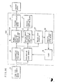
- FIG.14 is a block diagram of a fifth embodiment of the present invention.
- a counting means 25 memorizes numbers of occurrences of the abnormal state caused at operation of the shutoff means 4, classifying with respect to the flow rate and continuous time period, respectively, after reset of a normal condition of gas consumption in the varying means 12 of normal condition of gas consumption.
- a initial condition renewing means 26 renews the initial condition in the initial condition setting means 7 on the basis of a flow rate and continuous time period in the abnormal state, when numbers counted by the counting means 25 reach a predetermined number, and operation of the timer 9 starts.
- FIG.15(a), FIG.15(b) and FIG.15(c) shows a flow chart showing operation of the controller 55 as shown in FIG.14.
- the flow rate is measured by the flow rate measurement means 3 (Step A).
- the consumption state is detected by the consumption state detection means 6 (Step B).
- the operation of the timer 9 is examined by the starter signal generating means 10 (Step C).
- the timer 9 is in counting operation, the consumption state is memorized in the consumption-state memory 11, and the consumption state is always replaced with a new maximum consumption state (Step E).
- the consumption state detected by the consumption state detection means 6 is compared with the normal condition of gas consumption in the normal condition decision means of gas consumption 8 (Step D).
- the consumption state is recognized as an abnormal state (Step F), and occurrence of the abnormal state is counted with respect to the flow rate and the continuous time period, respectively (Step P).
- the consumption state is within the normal condition of gas consumption, if the varying means 12 of normal condition gas consumption is operated (Step H), the flow of the flow chart is returned to the Step A, and measurement of the flow rate is repeated.
- the varying means 12 of normal condition of gas consumption is not operated in the normal condition of the gas consumption, if the counting operation of the timer 9 is finished, the varying means 12 of normal condition of gas consumption is operated (Steps I and J).
- the maximum value of the consumption state memorized in the consumption-state memory 11 is compared with the initial condition of the initial condition setting means 7, and a smaller one thereof is memorized in the varying means 12 of normal condition of gas consumption (Step K).
- a consumption state detected by the consumption state detection means 6 is compared with the new normal condition of gas consumption (Step D).
- finish of the counting operation of the timer 9 is examined (Step L).
- the timer 9 is in the counting operation, the flow of the flow chart is returned to the Step A through the Step M.
- input of a starting signal is examined (Step N).
- the counting operation of the timer 9 is started by input of the starting signal (Step O).
- the flow of operation is returned to the Step A.
- Step T When the flow rate is zero, the closing signal is output.
- Step T When the flow rate is zero, input of the reset signal is examined (Step T).
- Step V change of the initial condition is examined (Step V), and when the initial condition has changed, the timer 9 is cleared (Step W).
- the initial condition is set in the initial setting condition means 7 (Step X), and subsequently, counting operation of the timer 9 starts (Step O).
- Step A the flow of the flow rate returns to measurement of the flow rate
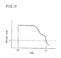
- FIG.17 is a graph showing a relation between the margin rate and lapse time.
- the abscissa is graduated by a lapse time and the ordinate is graduated by the margin rate.
- the normal condition of gas consumption is set, and operation of the margin rate detector 27 starts.
- a predetermined margin rate m is plotted by a horizontal dotted line. The margin rate is higher than the predetermined margin rate m from t0 to t1. After the time t1, the margin rate is lower than the predetermined margin rate m.
- the starting signal generating means 10 is operated again at the time t1, or after lapse of a predetermined time period wherein the margin rate is under the predetermined margin rate m, thereby a new gas consumption pattern is set in the varying means 12 of normal condition of gas consumption.
- the margin rate is selected to be lower than the predetermined margin rate m.
- the present invention is applicable in such a case that, on the contrary, the margin rate is exceeding a predetermined margin rate, also by using the margin rate detector 27 in accordance with the present invention. For instance, when one of the gas equipments is abandoned, the normal condition of gas consumption is reduced by the initial condition renewing means 26.
- the normal condition of gas consumption which is suitable to an actual use can be set before operation of the shutoff means by mean of the initial condition renewing means 26 on the basis of operation of the margin rate detector 27.
- the consumer of the gas shutoff apparatus in accordance with the present invention can add or decrease gas equipments without occurrence of gas interruption. Furthermore, safety is assured and convenience is improved.
- FIG.18 is a block diagram of a controller 57 of a seventh embodiment.
- the controller 57 comprises an initial condition reset means 28 for returning the condition of gas consumption set by the varying means 12 of normal condition of gas consumption to the initial condition.
- the initial condition reset means 28 comprises a switch, for example, and is controlled by a microcomputer. Then, in case that a lot of the gas is temporarily consumed, the gas shutoff apparatus is operable without unexpected shutoff by holding the reference value, which is larger than the consumption state and reset by the initial condition reset means 28 in a predetermined time period by a timer.
Landscapes
- Engineering & Computer Science (AREA)
- Physics & Mathematics (AREA)
- General Physics & Mathematics (AREA)
- Chemical & Material Sciences (AREA)
- Mechanical Engineering (AREA)
- Combustion & Propulsion (AREA)
- General Engineering & Computer Science (AREA)
- Business, Economics & Management (AREA)
- Emergency Management (AREA)
- Analytical Chemistry (AREA)
- Fluid Mechanics (AREA)
- Measuring Volume Flow (AREA)
- Control Of Combustion (AREA)
Applications Claiming Priority (6)
| Application Number | Priority Date | Filing Date | Title |
|---|---|---|---|
| JP248690/86 | 1986-10-20 | ||
| JP24869086A JPH0743125B2 (ja) | 1986-10-20 | 1986-10-20 | ガス遮断装置 |
| JP248688/86 | 1986-10-20 | ||
| JP248686/86 | 1986-10-20 | ||
| JP24868886A JPH0617747B2 (ja) | 1986-10-20 | 1986-10-20 | ガス遮断装置 |
| JP24868686A JPH0663639B2 (ja) | 1986-10-20 | 1986-10-20 | ガス遮断装置 |
Publications (3)
| Publication Number | Publication Date |
|---|---|
| EP0264856A2 true EP0264856A2 (fr) | 1988-04-27 |
| EP0264856A3 EP0264856A3 (en) | 1990-12-27 |
| EP0264856B1 EP0264856B1 (fr) | 1994-03-09 |
Family
ID=27333742
Family Applications (1)
| Application Number | Title | Priority Date | Filing Date |
|---|---|---|---|
| EP19870115173 Expired - Lifetime EP0264856B1 (fr) | 1986-10-20 | 1987-10-16 | Appareil pour couper un afflux de gaz |
Country Status (7)
| Country | Link |
|---|---|
| US (1) | US4866633A (fr) |
| EP (1) | EP0264856B1 (fr) |
| KR (1) | KR900008429B1 (fr) |
| AU (1) | AU589813B2 (fr) |
| CA (1) | CA1279715C (fr) |
| DE (1) | DE3789268T2 (fr) |
| HK (1) | HK87494A (fr) |
Cited By (17)
| Publication number | Priority date | Publication date | Assignee | Title |
|---|---|---|---|---|
| EP0328031A3 (en) * | 1988-02-10 | 1990-12-19 | Matsushita Electric Ind Co Ltd | Gas shutoff apparatus |
| EP0333161A3 (en) * | 1988-03-17 | 1990-12-19 | Matsushita Electric Industrial Co., Ltd. | Gas shutoff apparatus |
| GB2246226A (en) * | 1990-07-21 | 1992-01-22 | Stoves Ltd | Noxious fluid safety system |
| FR2667716A1 (fr) * | 1990-10-05 | 1992-04-10 | Mzoughi Abdelaziz | Procede et dispositif pour le gestion et la surveillance d'une installation de gaz. |
| EP0565474A1 (fr) * | 1992-03-10 | 1993-10-13 | D. Francisco Monforte Sanroma | Système de sécurité pour empêcher une fuite accidentelle dans un appareil à gaz |
| EP0507101A3 (en) * | 1991-04-04 | 1994-09-14 | Matsushita Electric Industrial Co Ltd | Flow amount measuring and controlling apparatus |
| WO1995016189A1 (fr) * | 1993-12-07 | 1995-06-15 | Schlumberger Industries S.A. | Procede et dispositif de surveillance de l'evolution de la valeur courante d'un debit de fluide dans un compteur de fluide |
| FR2729455A1 (fr) * | 1995-01-16 | 1996-07-19 | Bhiki Eric Ambroise | Gaz-systeme anti-fuite |
| FR2736431A1 (fr) * | 1995-07-05 | 1997-01-10 | Schlumberger Ind Sa | Organe de coupure a clapet anti-feu pour compteur de gaz et compteur de gaz equipe d'un tel organe de coupure |
| WO1998002857A1 (fr) * | 1996-07-11 | 1998-01-22 | Eric Bhiki | Systeme de protection contre les fuites de gaz |
| AU721784B2 (en) * | 1995-08-04 | 2000-07-13 | Gary Isaacson Jr. | Flood control device |
| US6119720A (en) * | 1995-08-04 | 2000-09-19 | Gary A. Isaacson, Jr. | Flood control device |
| GB2387007A (en) * | 2002-03-27 | 2003-10-01 | Simon Lawrence Smith | Monitoring of utility usage patterns from analysis of utility meters of a dwelling to detect abnormal use to protect the elderly or disabled occupant |
| ITTA20100002A1 (it) * | 2010-01-27 | 2011-07-28 | Martino Convertini | Dispositivo automatico di sicurezza gas |
| CN103806503A (zh) * | 2014-02-18 | 2014-05-21 | 谷振宇 | 物联网智能管网节水监控系统 |
| EP2360457A4 (fr) * | 2008-12-19 | 2014-08-27 | Panasonic Corp | Dispositif de fermeture de gaz |
| EP2175247A4 (fr) * | 2007-08-06 | 2014-09-03 | Panasonic Corp | Dispositif de mesure de débit, système de communication, procédé de mesure de débit, programme de mesure de débit, système d'alimentation de fluide, et dispositif de contrôle d'outil de gaz |
Families Citing this family (29)
| Publication number | Priority date | Publication date | Assignee | Title |
|---|---|---|---|---|
| US5047965A (en) * | 1989-01-05 | 1991-09-10 | Zlokovitz Robert J | Microprocessor controlled gas pressure regulator |
| JP2501661Y2 (ja) * | 1989-03-03 | 1996-06-19 | 株式会社イナックス | 定量吐水装置 |
| US5126934A (en) * | 1989-06-09 | 1992-06-30 | Smart House, L.P. | Gas distribution system |
| US5063519A (en) * | 1989-09-18 | 1991-11-05 | Pacific Energy | Landfill gas production testing and extraction method |
| US5902927A (en) | 1995-12-01 | 1999-05-11 | Perception Incorporated | Fluid metering apparatus and method |
| US5636653A (en) * | 1995-12-01 | 1997-06-10 | Perception Incorporated | Fluid metering apparatus and method |
| US6076542A (en) * | 1995-12-01 | 2000-06-20 | Perception Incorporated | Fluid metering method |
| KR100446268B1 (ko) * | 1998-09-11 | 2004-09-01 | 고아쓰 가스 호안 교카이 | 가스 누출 검출 시스템 |
| US6733276B1 (en) | 2003-03-04 | 2004-05-11 | Jeffrey R. Kopping | Gas shut-off device |
| WO2006043630A1 (fr) * | 2004-10-20 | 2006-04-27 | Matsushita Electric Industrial Co., Ltd. | Dispositif de blocage de gaz et procédé de blocage de gaz |
| KR20070103740A (ko) * | 2005-02-17 | 2007-10-24 | 마쯔시다덴기산교 가부시키가이샤 | 실장 조건 결정 방법, 실장 조건 결정 장치 및 실장기 |
| US7717294B2 (en) * | 2005-06-20 | 2010-05-18 | South-Tek Systems | Beverage dispensing gas consumption detection with alarm and backup operation |
| US9200939B2 (en) * | 2007-06-12 | 2015-12-01 | Panasonic Corporation | Flow rate measurement apparatus and fluid supply system |
| JP4544277B2 (ja) * | 2007-07-12 | 2010-09-15 | パナソニック株式会社 | ガス遮断装置 |
| JP4990818B2 (ja) * | 2008-03-07 | 2012-08-01 | パナソニック株式会社 | ガスメータ及びガス保安システム |
| US8040664B2 (en) | 2008-05-30 | 2011-10-18 | Itron, Inc. | Meter with integrated high current switch |
| JP5104704B2 (ja) * | 2008-10-08 | 2012-12-19 | パナソニック株式会社 | ガス遮断装置 |
| JP5293152B2 (ja) * | 2008-12-19 | 2013-09-18 | パナソニック株式会社 | ガス遮断装置 |
| EP2383513A1 (fr) * | 2009-01-29 | 2011-11-02 | Panasonic Corporation | Dispositif de coupure de gaz |
| US8493232B2 (en) * | 2009-09-30 | 2013-07-23 | Itron, Inc. | Gas shut-off valve with feedback |
| US8890711B2 (en) * | 2009-09-30 | 2014-11-18 | Itron, Inc. | Safety utility reconnect |
| BR112012007323A2 (pt) * | 2009-09-30 | 2019-09-24 | Itron Inc | desconexão remota de utilitário de um sistema de leitura de medidor. |
| US20110074601A1 (en) * | 2009-09-30 | 2011-03-31 | Itron, Inc. | Utility meter with flow rate sensitivity shut off |
| JP5439269B2 (ja) * | 2010-02-01 | 2014-03-12 | 東洋自動機株式会社 | 液状物充填機の充填通路開閉装置 |
| US9249988B2 (en) * | 2010-11-24 | 2016-02-02 | Grand Mate Co., Ted. | Direct vent/power vent water heater and method of testing for safety thereof |
| US9086068B2 (en) * | 2011-09-16 | 2015-07-21 | Grand Mate Co., Ltd. | Method of detecting safety of water heater |
| JP5789162B2 (ja) * | 2011-09-28 | 2015-10-07 | 京セラ株式会社 | エネルギー管理システム、ガスメータ及びエネルギー管理装置 |
| US9005423B2 (en) | 2012-12-04 | 2015-04-14 | Itron, Inc. | Pipeline communications |
| CN119778657A (zh) * | 2023-10-08 | 2025-04-08 | 金卡智能集团股份有限公司 | 燃气表和燃气监控系统 |
Family Cites Families (14)
| Publication number | Priority date | Publication date | Assignee | Title |
|---|---|---|---|---|
| GB1182786A (en) * | 1966-11-18 | 1970-03-04 | Ici Ltd | Control or Alarm Method and Apparatus. |
| US4074692A (en) * | 1971-10-15 | 1978-02-21 | Shafer Homer J | Pipeline break shutoff control |
| JPS5350863A (en) * | 1976-10-20 | 1978-05-09 | Hitachi Ltd | Demand quantity estimating apparatus for flow rate pressure controlling in piping network |
| US4241400A (en) * | 1978-12-18 | 1980-12-23 | General Electric Company | Microprocessor based control circuit for washing appliances |
| FR2468069A1 (fr) * | 1979-10-17 | 1981-04-30 | Foulon Michel | Appareil permettant de detecter l'existence d'une fuite dans un circuit parcouru de maniere discontinue par un fluide |
| AU530842B2 (en) * | 1980-07-04 | 1983-07-28 | Regioninvest Norr A.B. | Mass production unit for producing eggs of an insect |
| DK146455A (en) * | 1981-05-06 | 1900-01-01 | Method and plant for monitoring and detecting possible leak in a piping system | |
| JPS58700A (ja) * | 1981-06-26 | 1983-01-05 | Hitachi Ltd | 流体輸送システムの制御方式 |
| US4729106A (en) * | 1982-07-06 | 1988-03-01 | Institute Of Gas Technology | Fluid distribution to multiple users through distributed intelligence sub-centers |
| US4502842A (en) * | 1983-02-02 | 1985-03-05 | Colt Industries Operating Corp. | Multiple compressor controller and method |
| US4644478A (en) * | 1983-09-13 | 1987-02-17 | International Business Machines Corp. | Monitoring and alarm system for custom applications |
| US4574871A (en) * | 1984-05-07 | 1986-03-11 | Parkinson David W | Heat pump monitor apparatus for fault detection in a heat pump system |
| US4589435A (en) * | 1984-09-24 | 1986-05-20 | Aldrich Donald C | Water shutoff valve |
| GB2184260B (en) * | 1985-11-20 | 1989-11-01 | British Gas Plc | Valve operating system |
-
1987
- 1987-10-16 EP EP19870115173 patent/EP0264856B1/fr not_active Expired - Lifetime
- 1987-10-16 DE DE3789268T patent/DE3789268T2/de not_active Expired - Lifetime
- 1987-10-19 KR KR1019870011558A patent/KR900008429B1/ko not_active Expired
- 1987-10-19 CA CA 549615 patent/CA1279715C/fr not_active Expired - Lifetime
- 1987-10-20 AU AU79931/87A patent/AU589813B2/en not_active Expired
- 1987-10-20 US US07/110,390 patent/US4866633A/en not_active Expired - Lifetime
-
1994
- 1994-08-25 HK HK87494A patent/HK87494A/en not_active IP Right Cessation
Cited By (24)
| Publication number | Priority date | Publication date | Assignee | Title |
|---|---|---|---|---|
| EP0328031A3 (en) * | 1988-02-10 | 1990-12-19 | Matsushita Electric Ind Co Ltd | Gas shutoff apparatus |
| EP0333161A3 (en) * | 1988-03-17 | 1990-12-19 | Matsushita Electric Industrial Co., Ltd. | Gas shutoff apparatus |
| GB2246226A (en) * | 1990-07-21 | 1992-01-22 | Stoves Ltd | Noxious fluid safety system |
| GB2246226B (en) * | 1990-07-21 | 1995-02-01 | Stoves Ltd | Improvements in or relating to safety systems |
| FR2667716A1 (fr) * | 1990-10-05 | 1992-04-10 | Mzoughi Abdelaziz | Procede et dispositif pour le gestion et la surveillance d'une installation de gaz. |
| EP0507101A3 (en) * | 1991-04-04 | 1994-09-14 | Matsushita Electric Industrial Co Ltd | Flow amount measuring and controlling apparatus |
| US5369598A (en) * | 1991-04-04 | 1994-11-29 | Matsushita Electric Industrial Co., Ltd. | Flow amount measuring and controlling apparatus |
| EP0565474A1 (fr) * | 1992-03-10 | 1993-10-13 | D. Francisco Monforte Sanroma | Système de sécurité pour empêcher une fuite accidentelle dans un appareil à gaz |
| WO1995016189A1 (fr) * | 1993-12-07 | 1995-06-15 | Schlumberger Industries S.A. | Procede et dispositif de surveillance de l'evolution de la valeur courante d'un debit de fluide dans un compteur de fluide |
| FR2713760A1 (fr) * | 1993-12-07 | 1995-06-16 | Schlumberger Ind Sa | Procédé et dispositif de surveillance de l'évolution de la valeur courante d'un débit de fluide dans un compteur de fluide. |
| TR28272A (tr) * | 1993-12-07 | 1996-04-24 | Schlumberger Ind Sa | Bir akiskan madde sayacinda, cari akiskan madde akis gücü degerinin hareketlerini kontrol etme yöntemi ve aygiti. |
| FR2729455A1 (fr) * | 1995-01-16 | 1996-07-19 | Bhiki Eric Ambroise | Gaz-systeme anti-fuite |
| FR2736431A1 (fr) * | 1995-07-05 | 1997-01-10 | Schlumberger Ind Sa | Organe de coupure a clapet anti-feu pour compteur de gaz et compteur de gaz equipe d'un tel organe de coupure |
| WO1997002472A1 (fr) * | 1995-07-05 | 1997-01-23 | Schlumberger Industries S.A. | Organe de coupure a clapet antifeu pour compteur de gaz et compteur de gaz equipe d'un tel organe de coupure |
| AU721784B2 (en) * | 1995-08-04 | 2000-07-13 | Gary Isaacson Jr. | Flood control device |
| US6119720A (en) * | 1995-08-04 | 2000-09-19 | Gary A. Isaacson, Jr. | Flood control device |
| WO1998002857A1 (fr) * | 1996-07-11 | 1998-01-22 | Eric Bhiki | Systeme de protection contre les fuites de gaz |
| GB2387007A (en) * | 2002-03-27 | 2003-10-01 | Simon Lawrence Smith | Monitoring of utility usage patterns from analysis of utility meters of a dwelling to detect abnormal use to protect the elderly or disabled occupant |
| GB2387007B (en) * | 2002-03-27 | 2004-02-18 | Simon Lawrence Smith | System for monitoring an inhabited environment |
| EP2175247A4 (fr) * | 2007-08-06 | 2014-09-03 | Panasonic Corp | Dispositif de mesure de débit, système de communication, procédé de mesure de débit, programme de mesure de débit, système d'alimentation de fluide, et dispositif de contrôle d'outil de gaz |
| EP2360457A4 (fr) * | 2008-12-19 | 2014-08-27 | Panasonic Corp | Dispositif de fermeture de gaz |
| ITTA20100002A1 (it) * | 2010-01-27 | 2011-07-28 | Martino Convertini | Dispositivo automatico di sicurezza gas |
| CN103806503A (zh) * | 2014-02-18 | 2014-05-21 | 谷振宇 | 物联网智能管网节水监控系统 |
| CN103806503B (zh) * | 2014-02-18 | 2015-02-25 | 谷振宇 | 物联网智能管网节水监控系统 |
Also Published As
| Publication number | Publication date |
|---|---|
| DE3789268D1 (de) | 1994-04-14 |
| US4866633A (en) | 1989-09-12 |
| EP0264856A3 (en) | 1990-12-27 |
| KR900008429B1 (ko) | 1990-11-20 |
| CA1279715C (fr) | 1991-01-29 |
| EP0264856B1 (fr) | 1994-03-09 |
| AU589813B2 (en) | 1989-10-19 |
| KR880005404A (ko) | 1988-06-29 |
| AU7993187A (en) | 1988-04-21 |
| DE3789268T2 (de) | 1994-06-16 |
| HK87494A (en) | 1994-09-02 |
Similar Documents
| Publication | Publication Date | Title |
|---|---|---|
| EP0264856A2 (fr) | Appareil pour couper un afflux de gaz | |
| US5784245A (en) | Solenoid driver and method for determining solenoid operational status | |
| CA2277001C (fr) | Indicateur d'anomalie a declenchement variable | |
| US5152252A (en) | Water treatment control system for a boiler | |
| CA1118496A (fr) | Bloc d'alimentation auxiliaire et minuterie pour indicateurs-enregistreurs multifonctionnels de consommation d'electricite | |
| JP3170381B2 (ja) | 電池の寿命判定装置 | |
| US5812061A (en) | Sensor condition indicating system | |
| US5880920A (en) | Method and apparatus for controlling an electromagnetic switching member | |
| EP0333161B1 (fr) | Appareil coupe-circuit de gaz | |
| WO2000039822A1 (fr) | Procede de detection de declenchements manuels dans un dispositif electronique intelligent | |
| US4928728A (en) | Gas shutoff apparatus | |
| JPH06281708A (ja) | 電池寿命検査装置 | |
| JP2003043076A (ja) | ラッチングリレー内蔵電気機器及び電力量計 | |
| JP2004308833A (ja) | ガス遮断装置 | |
| JP4508149B2 (ja) | ガス遮断装置 | |
| JP2522195Y2 (ja) | ガスメータ装置 | |
| JPS58179729A (ja) | 燃料遮断制御装置 | |
| JP2570346Y2 (ja) | ガス遮断装置 | |
| JPS59122818A (ja) | ガス遮断装置 | |
| JPH08210631A (ja) | ガス保安装置のセンサー入出力装置 | |
| JP2003018751A (ja) | 遮断装置 | |
| JPH01135974A (ja) | ガス遮断弁の制御装置 | |
| JPH09127162A (ja) | 電圧検出回路 | |
| MXPA99006449A (es) | Indicador de falla de desconexion variable | |
| JPH09310781A (ja) | ガス遮断装置 |
Legal Events
| Date | Code | Title | Description |
|---|---|---|---|
| PUAI | Public reference made under article 153(3) epc to a published international application that has entered the european phase |
Free format text: ORIGINAL CODE: 0009012 |
|
| AK | Designated contracting states |
Kind code of ref document: A2 Designated state(s): DE FR GB |
|
| PUAL | Search report despatched |
Free format text: ORIGINAL CODE: 0009013 |
|
| AK | Designated contracting states |
Kind code of ref document: A3 Designated state(s): DE FR GB |
|
| 17P | Request for examination filed |
Effective date: 19901211 |
|
| 17Q | First examination report despatched |
Effective date: 19921117 |
|
| GRAA | (expected) grant |
Free format text: ORIGINAL CODE: 0009210 |
|
| AK | Designated contracting states |
Kind code of ref document: B1 Designated state(s): DE FR GB |
|
| REF | Corresponds to: |
Ref document number: 3789268 Country of ref document: DE Date of ref document: 19940414 |
|
| ET | Fr: translation filed | ||
| PLBE | No opposition filed within time limit |
Free format text: ORIGINAL CODE: 0009261 |
|
| STAA | Information on the status of an ep patent application or granted ep patent |
Free format text: STATUS: NO OPPOSITION FILED WITHIN TIME LIMIT |
|
| 26N | No opposition filed | ||
| REG | Reference to a national code |
Ref country code: GB Ref legal event code: 746 Effective date: 19960820 |
|
| REG | Reference to a national code |
Ref country code: GB Ref legal event code: IF02 |
|
| PGFP | Annual fee paid to national office [announced via postgrant information from national office to epo] |
Ref country code: GB Payment date: 20061011 Year of fee payment: 20 |
|
| PGFP | Annual fee paid to national office [announced via postgrant information from national office to epo] |
Ref country code: DE Payment date: 20061012 Year of fee payment: 20 |
|
| REG | Reference to a national code |
Ref country code: GB Ref legal event code: PE20 |
|
| PG25 | Lapsed in a contracting state [announced via postgrant information from national office to epo] |
Ref country code: GB Free format text: LAPSE BECAUSE OF EXPIRATION OF PROTECTION Effective date: 20071015 |
|
| PGFP | Annual fee paid to national office [announced via postgrant information from national office to epo] |
Ref country code: FR Payment date: 20061010 Year of fee payment: 20 |