EP0264907A2 - Chaudière de chauffage à combustibles liquides - Google Patents
Chaudière de chauffage à combustibles liquides Download PDFInfo
- Publication number
- EP0264907A2 EP0264907A2 EP87115339A EP87115339A EP0264907A2 EP 0264907 A2 EP0264907 A2 EP 0264907A2 EP 87115339 A EP87115339 A EP 87115339A EP 87115339 A EP87115339 A EP 87115339A EP 0264907 A2 EP0264907 A2 EP 0264907A2
- Authority
- EP
- European Patent Office
- Prior art keywords
- boiler according
- combustion chamber
- heat exchanger
- boiler
- double jacket
- Prior art date
- Legal status (The legal status is an assumption and is not a legal conclusion. Google has not performed a legal analysis and makes no representation as to the accuracy of the status listed.)
- Withdrawn
Links
Images
Classifications
-
- F—MECHANICAL ENGINEERING; LIGHTING; HEATING; WEAPONS; BLASTING
- F24—HEATING; RANGES; VENTILATING
- F24H—FLUID HEATERS, e.g. WATER OR AIR HEATERS, HAVING HEAT-GENERATING MEANS, e.g. HEAT PUMPS, IN GENERAL
- F24H1/00—Water heaters, e.g. boilers, continuous-flow heaters or water-storage heaters
- F24H1/10—Continuous-flow heaters, i.e. heaters in which heat is generated only while the water is flowing, e.g. with direct contact of the water with the heating medium
- F24H1/107—Continuous-flow heaters, i.e. heaters in which heat is generated only while the water is flowing, e.g. with direct contact of the water with the heating medium using fluid fuel
-
- F—MECHANICAL ENGINEERING; LIGHTING; HEATING; WEAPONS; BLASTING
- F24—HEATING; RANGES; VENTILATING
- F24H—FLUID HEATERS, e.g. WATER OR AIR HEATERS, HAVING HEAT-GENERATING MEANS, e.g. HEAT PUMPS, IN GENERAL
- F24H1/00—Water heaters, e.g. boilers, continuous-flow heaters or water-storage heaters
- F24H1/22—Water heaters other than continuous-flow or water-storage heaters, e.g. water heaters for central heating
- F24H1/38—Water heaters other than continuous-flow or water-storage heaters, e.g. water heaters for central heating with water contained in separate elements, e.g. radiator-type element
-
- F—MECHANICAL ENGINEERING; LIGHTING; HEATING; WEAPONS; BLASTING
- F24—HEATING; RANGES; VENTILATING
- F24H—FLUID HEATERS, e.g. WATER OR AIR HEATERS, HAVING HEAT-GENERATING MEANS, e.g. HEAT PUMPS, IN GENERAL
- F24H8/00—Fluid heaters characterised by means for extracting latent heat from flue gases by means of condensation
-
- Y—GENERAL TAGGING OF NEW TECHNOLOGICAL DEVELOPMENTS; GENERAL TAGGING OF CROSS-SECTIONAL TECHNOLOGIES SPANNING OVER SEVERAL SECTIONS OF THE IPC; TECHNICAL SUBJECTS COVERED BY FORMER USPC CROSS-REFERENCE ART COLLECTIONS [XRACs] AND DIGESTS
- Y02—TECHNOLOGIES OR APPLICATIONS FOR MITIGATION OR ADAPTATION AGAINST CLIMATE CHANGE
- Y02B—CLIMATE CHANGE MITIGATION TECHNOLOGIES RELATED TO BUILDINGS, e.g. HOUSING, HOUSE APPLIANCES OR RELATED END-USER APPLICATIONS
- Y02B30/00—Energy efficient heating, ventilation or air conditioning [HVAC]
Definitions
- the invention relates to a boiler for liquid fuels with a combustion chamber with a burner, a fume hood for the flue gases and a heat exchanger located in the area of this fume hood.
- the energy content of fuels is indicated by the calorific value.
- the calorific value of a fuel is the amount of heat that is released when the fuel is completely burnt, if the initial and end products are at the same temperature and the water vapor produced during the combustion is in liquid form.
- the calorific value of a fuel is the amount of heat that is released during complete combustion if the water generated during the combustion is in vapor form.
- the chemically bound or molecular hydrogen content of the fuel thus determines the ratio of the calorific value to the calorific value. The higher the hydrogen content, the greater the ratio of calorific value: calorific value.
- the calorific value of city gas is 5.48 kWh / m3, while the calorific value is 4.87 kWh / m3.
- the ratio of calorific value: calorific value is therefore 1: 1.13.
- the calorific value of extra light heating oil is 12.57 kWh / kg and the calorific value is 11.86 kWh / kg. This gives a ratio of 1.06.
- the calorific value of light heating oil is 12.42 kWh / kg.
- the object of the present invention is to provide a boiler for liquid fuels which can be operated using the condensing method and in which the heating surfaces clean themselves.
- this is achieved by a water tank which is independent of the heat exchanger and from which steam is released into the boiler and by a condensate collecting device which feeds the condensed steam back to the water tank after it has passed or passed through the heat exchanger together with the flue gases.
- the water tank is advantageously formed by a double jacket surrounding the combustion chamber.
- the boiler according to the invention has two water circuits, the first of which is used to generate steam and the second, which is passed through the heat exchanger, in the conventional sense of producing heating water.
- An embodiment of the invention is characterized by a riser pipe for the flue gases emerging above the heat exchanger, which surrounds the heat exchanger and which leads away from the combustion chamber and which has a double jacket which is connected to the water tank and is provided at the top with an outlet opening for the water vapor.
- An embodiment of the invention provides that the combustion chamber is aligned horizontally, and that the riser pipe arranged opposite the burner extends with its lower end to approximately the height of the burner.
- the double jacket of the riser pipe is provided with two vertically offset connections on the water tank.
- a further exemplary embodiment of the invention provides that the condensate collecting device comprises a collecting container which is connected to the water container by means of a pipe, a backflow preventer being provided at the inlet to the water container.
- the riser pipe and the steam-guiding double jacket are surrounded by insulation, for example an air jacket, in the area of the heat exchanger.
- the water container emits water vapor directly into the combustion chamber.
- Water vapor is released, for example, via outlet openings which are arranged in one or more rows of holes in the upper cover of the combustion chamber.
- the outlet openings can also be slots.
- One embodiment of the invention provides at least one horizontal cover plate for the flue gases which projects into the combustion chamber.
- the cover plates are advantageously double executed wall. This prevents the cover plate from deforming.
- the exhaust gas and the water vapor generated are passed through the heat exchanger.
- the water vapor contained therein condenses, which is collected in an expansion tank and then flows back into the evaporator.
- the condensate level is regulated in that the height-adjustable overflow located in the expansion tank forcibly determines the level of the condensate level in the evaporator.
- An embodiment of the invention provides that a siphon is formed in the collecting container.
- a height-adjustable condensate overflow leads away from the collecting container.
- the setting of the condensate overflow determines the height of the water level in the collecting tank and at the same time in the evaporator.
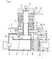
- the boiler according to the invention has a boiler room 1 into which a burner 3 projects.
- the burner 3 is aligned horizontally.
- the boiler has a partially water-filled double jacket 2, which surrounds the combustion chamber 1.
- the flue gases get out of the combustion chamber 1 into a path Pipe 5, pass through the heat exchanger 10 and finally pass through a collecting pipe 14 for the condensate into the exhaust pipe 17, which forms the chimney connection.
- the basic components of the boiler, the double jacket 2 which surrounds the combustion chamber 1, the riser pipe 5 and the heat exchanger 10 as well as the collecting pipe 14 and a collecting container 16 for the condensate are the same in both exemplary embodiments. However, the exemplary embodiments differ in various design changes.
- FIG. 1 The exemplary embodiment of FIG. 1 is described below.
- the double jacket 2 is provided on the inside with outlet openings 4, through which water vapor can be released into the combustion chamber 2.
- baffles 6, 6 ' In order to prevent the water vapor from being immediately drawn off into the riser pipe 5, two baffles 6, 6 'are provided.
- the arrows show the main steam flow.
- baffle plate 7 In the combustion chamber 1 there is a horizontal baffle plate 7, which at the end facing the burner 3 has a web 8 pointing upwards. Through the baffle 7, the exhaust gases are forced to take the path shown by arrows to get to the riser 5.
- the baffle 7 and the web 8 are designed in the embodiment as a double jacket.
- the baffle 7 and the web 8 form a cup in which boiled water is collected and returned to the double jacket 2 through the overflow line 24.
- a fan 9 is arranged at the upper end of the riser pipe 5.
- the riser pipe 5 is surrounded by a heat exchanger 10.
- the exhaust gases are sucked in by the fan 9 and then passed through the heat exchanger 10 from top to bottom.
- the speed of the fan 9 or the opening angle of the flap 26 can be regulated in a conventional manner.
- the heat exchanger 10 is provided in a conventional manner with an inlet 11 and an outlet 12.
- the inlet 11 is at the bottom, while the outlet 12 is at the top.
- the cooled exhaust gases enter the collecting pipe 14, the water vapor contained therein condensing through the cooling.
- the condensate is fed to a collecting container 16 via a line 15.
- the exhaust gases can escape to the outside via a chimney connection 17.
- the collecting container 16 is connected via a line 18 to the double jacket 2, which surrounds the combustion chamber, and has an outflow line 19 which releases excess condensate. This is regulated by the adjustable overflow 20, which leads to a neutralization station 21.
- a siphon is arranged in the collecting container 16. Furthermore, the collecting container 16 has a drain line 22 which is closed by a valve 23. The inlet valve 25 is used for filling.
- the overflow line 24 leads boiled water back into the double jacket 2.
- the inlet of the overflow line is 3 mm above the baffle plate 7.
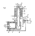
- the riser pipe 5 does not open into the combustion chamber 1 from above, but is guided laterally past this to approximately the height of the burner 3.
- the flue gases pass from the combustion chamber 1 into the riser pipe 5 in the direction of the arrows.
- the riser pipe 5 is surrounded by a double jacket 27, which is connected via connecting lines 29 to the double jacket 2, which surrounds the combustion chamber 1.
- the double jacket 27 has an opening 28 at the top.
- the water heated by the heating gases becomes steam in the double jacket 27, which emerges at the opening 28 and mixes with the flue gases at the point denoted by M.
- the double jacket 27 is provided with insulation in the area of the heat exchanger 10, but this insulation extends over the entire height of the heat exchanger 10.
- the isolation from one Air jacket 31 formed In the exemplary embodiment, the isolation from one Air jacket 31 formed. However, an insulating material 13 could also be provided in the exemplary embodiment according to FIG. 1.
- the riser pipe 5 is preferably provided with a sleeve 33 with an edge 34. By pulling the sleeve 33 out more or less, it can be regulated whether the fan 32 draws out more steam or flue gas.
- the condensate collects in the collecting pipe 14, while the flue gases emerge via the chimney connection 17.
- the condensate arrives in the collecting container 16 and is partly returned from there via the line 18 to the double jacket 2.
- the excess condensate reaches the neutralization station 21, as in the previously described exemplary embodiment, and from there into the waste water.
- a check valve 30 When passing from the line to the double jacket 2, a check valve 30 is also arranged.
Landscapes
- Engineering & Computer Science (AREA)
- Physics & Mathematics (AREA)
- Thermal Sciences (AREA)
- Chemical & Material Sciences (AREA)
- Combustion & Propulsion (AREA)
- Mechanical Engineering (AREA)
- General Engineering & Computer Science (AREA)
- Heat-Exchange Devices With Radiators And Conduit Assemblies (AREA)
Applications Claiming Priority (2)
| Application Number | Priority Date | Filing Date | Title |
|---|---|---|---|
| AT279186 | 1986-10-21 | ||
| AT2791/86 | 1986-10-21 |
Publications (2)
| Publication Number | Publication Date |
|---|---|
| EP0264907A2 true EP0264907A2 (fr) | 1988-04-27 |
| EP0264907A3 EP0264907A3 (fr) | 1989-09-20 |
Family
ID=3540343
Family Applications (1)
| Application Number | Title | Priority Date | Filing Date |
|---|---|---|---|
| EP87115339A Withdrawn EP0264907A3 (fr) | 1986-10-21 | 1987-10-20 | Chaudière de chauffage à combustibles liquides |
Country Status (1)
| Country | Link |
|---|---|
| EP (1) | EP0264907A3 (fr) |
Cited By (13)
| Publication number | Priority date | Publication date | Assignee | Title |
|---|---|---|---|---|
| EP0332550A3 (en) * | 1988-03-08 | 1990-03-07 | Yves Dalle | Process and generators for simultaneously producing hot drinking water and carbon dioxide, and agricultural plants using same |
| FR2678047A1 (fr) * | 1991-06-18 | 1992-12-24 | Equip Technic | Dispositif de traitement des fumees chaudes et polluees, notamment acides, provenant de la combustion du fuel dans une chaudiere industrielle ou de chauffage urbain. |
| GB2415032A (en) * | 2004-06-11 | 2005-12-14 | Baxi Spa | High efficiency boiler with flue gas heat recovery |
| CN100362290C (zh) * | 2005-11-09 | 2008-01-16 | 张祥文 | 环保节能采暖炉 |
| CN100449220C (zh) * | 2007-03-06 | 2009-01-07 | 成都前锋热交换器有限责任公司 | 冷凝式热交换器 |
| CN101995089A (zh) * | 2010-10-30 | 2011-03-30 | 孙延吾 | 一种水暖锅炉 |
| WO2011060524A1 (fr) * | 2009-11-20 | 2011-05-26 | Aloha Energy Solution Inc. | Système de chauffage d'eau |
| CN102322686A (zh) * | 2011-09-28 | 2012-01-18 | 山东水龙王集团有限公司 | 自带热源的真空热水机组 |
| EP2458299A3 (fr) * | 2010-11-24 | 2012-08-15 | Zenex Technologies Limited | Chauffage |
| CN103017128A (zh) * | 2012-12-13 | 2013-04-03 | 诸城市电力大众木器有限公司 | 环保型自循环加热蒸发器 |
| DE102015113446A1 (de) | 2015-08-14 | 2017-06-01 | Hermann Bock Gmbh | Bett, insbesondere Kranken- und/oder Pflegebett |
| CN109682071A (zh) * | 2019-01-23 | 2019-04-26 | 浙江双菱戴纳斯帝电气有限公司 | 冷凝式集水装置及具有冷凝式集水装置的壁挂炉 |
| CN111928220A (zh) * | 2020-08-20 | 2020-11-13 | 刘维 | 一种顶部进风的蒸汽炉 |
Family Cites Families (3)
| Publication number | Priority date | Publication date | Assignee | Title |
|---|---|---|---|---|
| GB1108492A (en) * | 1965-07-24 | 1968-04-03 | Newton Robert Park | Water heater |
| DE2425100A1 (de) * | 1974-05-24 | 1975-12-11 | Bosch Gmbh Robert | Heizgeraet, insbesondere wassererhitzer, mit einem brenner fuer feste, fluessige, oder gasfoermige brennstoffe |
| FR2571836B1 (fr) * | 1984-10-16 | 1987-01-16 | Gaz De France | Procede de chauffage d'un liquide par combustion submergee et dispositif pour la mise en oeuvre du procede |
-
1987
- 1987-10-20 EP EP87115339A patent/EP0264907A3/fr not_active Withdrawn
Cited By (14)
| Publication number | Priority date | Publication date | Assignee | Title |
|---|---|---|---|---|
| EP0332550A3 (en) * | 1988-03-08 | 1990-03-07 | Yves Dalle | Process and generators for simultaneously producing hot drinking water and carbon dioxide, and agricultural plants using same |
| FR2678047A1 (fr) * | 1991-06-18 | 1992-12-24 | Equip Technic | Dispositif de traitement des fumees chaudes et polluees, notamment acides, provenant de la combustion du fuel dans une chaudiere industrielle ou de chauffage urbain. |
| GB2415032A (en) * | 2004-06-11 | 2005-12-14 | Baxi Spa | High efficiency boiler with flue gas heat recovery |
| GB2415032B (en) * | 2004-06-11 | 2009-11-04 | Baxi Spa | High efficiency boiler with flue gas heat recovery |
| CN100362290C (zh) * | 2005-11-09 | 2008-01-16 | 张祥文 | 环保节能采暖炉 |
| CN100449220C (zh) * | 2007-03-06 | 2009-01-07 | 成都前锋热交换器有限责任公司 | 冷凝式热交换器 |
| WO2011060524A1 (fr) * | 2009-11-20 | 2011-05-26 | Aloha Energy Solution Inc. | Système de chauffage d'eau |
| CN101995089A (zh) * | 2010-10-30 | 2011-03-30 | 孙延吾 | 一种水暖锅炉 |
| EP2458299A3 (fr) * | 2010-11-24 | 2012-08-15 | Zenex Technologies Limited | Chauffage |
| CN102322686A (zh) * | 2011-09-28 | 2012-01-18 | 山东水龙王集团有限公司 | 自带热源的真空热水机组 |
| CN103017128A (zh) * | 2012-12-13 | 2013-04-03 | 诸城市电力大众木器有限公司 | 环保型自循环加热蒸发器 |
| DE102015113446A1 (de) | 2015-08-14 | 2017-06-01 | Hermann Bock Gmbh | Bett, insbesondere Kranken- und/oder Pflegebett |
| CN109682071A (zh) * | 2019-01-23 | 2019-04-26 | 浙江双菱戴纳斯帝电气有限公司 | 冷凝式集水装置及具有冷凝式集水装置的壁挂炉 |
| CN111928220A (zh) * | 2020-08-20 | 2020-11-13 | 刘维 | 一种顶部进风的蒸汽炉 |
Also Published As
| Publication number | Publication date |
|---|---|
| EP0264907A3 (fr) | 1989-09-20 |
Similar Documents
| Publication | Publication Date | Title |
|---|---|---|
| EP0264907A2 (fr) | Chaudière de chauffage à combustibles liquides | |
| DE2846120C2 (de) | Wasserspeichererhitzer | |
| DE2950901A1 (de) | Zentralheizungsanlage | |
| CH687644A5 (de) | Einrichtung mit einem Abgasrohr. | |
| DE3329777C2 (fr) | ||
| DE2040797A1 (de) | Baeckerei-Backofen | |
| EP0044401A1 (fr) | Cheminée | |
| DE20209753U1 (de) | Heizgerät mit einer Brennkammer | |
| DE4430726A1 (de) | Heizkessel zur Brennwertnutzung und ein Verfahren zum Betreiben dieses Heizkessels | |
| CH690136A5 (de) | Heizanlage mit Wärmetauscher. | |
| DE3519727C2 (fr) | ||
| EP0123869B1 (fr) | Chaudière à puissance calorifique notamment pour la génération d'eau chaude ou d'eau chauffante avec un brûleur à gaz | |
| CH678655A5 (fr) | ||
| AT100003B (de) | Mit Gas beheizter Flüssigkeitserhitzer. | |
| EP0047565A2 (fr) | Poêle pour combustibles solides, liquides ou gazeux | |
| DE202004008763U1 (de) | Heizkessel | |
| DE2538211C3 (de) | Heizungskessel | |
| CH657912A5 (de) | Gasbeheizte kesselanlage. | |
| DE3507252C2 (fr) | ||
| DE29814868U1 (de) | Heizkessel | |
| DE69003657T2 (de) | Wärmetauscheinheit für Lufterhitzer. | |
| DE19912273C2 (de) | Kamin mit äußerer Wasserfläche | |
| AT116067B (de) | Ofen zur ununterbrochenen Verkohlung. | |
| DE4406141A1 (de) | Vorrichtung zur Erwärmung von Heiz- und Brauchwasser | |
| DE400396C (de) | Mit Gas beheizter Fluessigkeitserhitzer |
Legal Events
| Date | Code | Title | Description |
|---|---|---|---|
| PUAI | Public reference made under article 153(3) epc to a published international application that has entered the european phase |
Free format text: ORIGINAL CODE: 0009012 |
|
| AK | Designated contracting states |
Kind code of ref document: A2 Designated state(s): AT BE CH DE ES FR GB IT LI NL SE |
|
| PUAL | Search report despatched |
Free format text: ORIGINAL CODE: 0009013 |
|
| AK | Designated contracting states |
Kind code of ref document: A3 Designated state(s): AT BE CH DE ES FR GB IT LI NL SE |
|
| 17P | Request for examination filed |
Effective date: 19891031 |
|
| 17Q | First examination report despatched |
Effective date: 19900814 |
|
| STAA | Information on the status of an ep patent application or granted ep patent |
Free format text: STATUS: THE APPLICATION IS DEEMED TO BE WITHDRAWN |
|
| 18D | Application deemed to be withdrawn |
Effective date: 19910226 |