EP0264963A2 - Verfahren und Anordnung zur Erzeugung von Fernsehtrickeffekten - Google Patents
Verfahren und Anordnung zur Erzeugung von Fernsehtrickeffekten Download PDFInfo
- Publication number
- EP0264963A2 EP0264963A2 EP87115623A EP87115623A EP0264963A2 EP 0264963 A2 EP0264963 A2 EP 0264963A2 EP 87115623 A EP87115623 A EP 87115623A EP 87115623 A EP87115623 A EP 87115623A EP 0264963 A2 EP0264963 A2 EP 0264963A2
- Authority
- EP
- European Patent Office
- Prior art keywords
- word
- address
- sequence
- address words
- spatial relationship
- Prior art date
- Legal status (The legal status is an assumption and is not a legal conclusion. Google has not performed a legal analysis and makes no representation as to the accuracy of the status listed.)
- Granted
Links
Images


Classifications
-
- H—ELECTRICITY
- H04—ELECTRIC COMMUNICATION TECHNIQUE
- H04N—PICTORIAL COMMUNICATION, e.g. TELEVISION
- H04N5/00—Details of television systems
- H04N5/222—Studio circuitry; Studio devices; Studio equipment
- H04N5/262—Studio circuits, e.g. for mixing, switching-over, change of character of image, other special effects ; Cameras specially adapted for the electronic generation of special effects
- H04N5/272—Means for inserting a foreground image in a background image, i.e. inlay, outlay
Definitions
- This invention relates to a method and apparatus for carrying out television special effects.
- a television picture is a representation in substantially planar form of a scene that is composed by the producer of a television program.
- the scene may be composed of tangible objects, or it may be at least partially synthesized by artificial means, e.g. a television graphics system, so that the source of the video signal representing the scene is not a camera or a film scanner but a frame buffer and a computer used for adjusting the contents of the frame buffer.
- the scene is made up of two component scenes, namely a foreground scene and a background scene, that are combined using a travelling matte technique.
- the foreground scene might contain an annulus against a solid color matte and the background scene a square against a screen of contrasting color, as shown in FIGS. 1(a) and 1(b) respectively, so that when the foreground and background scenes are combined the resulting picture has the appearance shown in FIG. 1(c).
- a transform system operates on the video signal representing a scene, and may be used to carry out a spatial transformation on the scene. For example, the scene may be displaced to the right. If the foreground video signal representing the FIG. 1(a) scene is applied to a transform system which carries out a transformation of the signal such that the transformed signal represents the scene shown in Fig. 1(d), in which the annulus of the FIG. 1(a) scene has been shifted to the right, then the signal obtained by combining the transformed foreground signal with the background signal might represent the picture shown in FIG. 1(e).
- Most transform systems are of two main kinds, known as the forward transform system and the frame-based frame-based reverse transform system.
- FIG. 2 represents a reverse transform system based on principles that are known at present. It is believed that the FIG. 2 system does not exist in the prior art, and it is being described in order to provide information that will be useful in understanding the invention.
- the transform system shown in FIG. 2 operates by digitizing the input video signal under control of a write clock 10 and writing the resulting sequence of digital words, each having, e.g. ten bits, into a video frame buffer 12 using addresses generated by a forward address generator 14.
- the input video signal is derived from an analog composite video signal in conventional interlaced format by separating it into its components (normally luminance and chrominance) and digitizing each component.
- the sampling rate for each of the chrominance components is only half that for the luminance component.
- the frame buffer 12 comprises a memory for storing the luminance component and a memory storing the chrominance components. However, since the components are acted on in like manner in the transform system, it is not necessary to consider the components separately.
- the operation of digitizing the video signal effectively resolves each raster line of the picture into multiple pixels, e.g. 720 pixels, that are small, but finite, in area.
- the location of a pixel in the scene can be defined by a two-coor dinate display address (U, V) of the input screen (FIG. 1(a), e.g.).
- the address space of the video frame buffer is organized so that there is one-to-one correspondence between the display addresses and the memory addresses generated by the forward address generator 14.
- the digital word representing the pixel having the display address (U, V) is written into the frame buffer 12 at a location that has a memory address that can be expressed as (U, V).
- a read address counter 16 operates under control of a read clock 17 to generate a sequence of addresses (X, Y) defining the locations in the output screen (FIG. 1(d)) of the pixels that will be successively addressed.
- the coordinate values X and Y each have the same number of significant digits as the coordinate values U and V respectively.
- the display addresses (X, Y) define the same possible pixel positions in the output display space as are defined in the input display space by the display addresses (U, V). However, the display addresses (X, Y) are not used directly to read the output video signal from the frame buffer.
- a reverse address generator 18 receives the output scene display addresses (X, Y) and multiplies them by a transform matrix T ⁇ to generate corresponding memory addresses (X ⁇ , Y ⁇ ) which are used to read the video signal from the frame buffer.
- the transform matrix T ⁇ is applied to the reverse address generator 18 by a user interface 19, and defines the nature of the transform that is effected by the reverse transform system If, for example, it is desired to effect a transformation in which the input scene is displaced diagonally upwards and to the left by an amount equal to the inter-pixel pitch in the diagonal direction, the transform matrix would be such that the memory address (X ⁇ , Y ⁇ ) that is generated in response to the display address (X, Y) would be (X+1, Y+1), assuming that the origin of the coordinate system is in the upper left corner of the input and output scene, and values of X and Y increase to the right and downwards respectively.
- the frame buffer 12 outputs the respective digital words representing an array of pixels surrounding the position defined by the reverse address (X ⁇ , Y ⁇ ). For example, the data words representing the four pixels nearest the point defined by the address (X ⁇ , Y ⁇ ) might be provided.
- the range of possible reverse addresses is greater than the range of memory addresses defining locations in the frame buffer 12, so that a validly-generated reverse address might define a location that does not exist in the frame buffer's address space. Therefore, the reverse addresses are also applied to an address limit detector 22 which responds to an invalid reverse address (an address which defines a location outside the address space of the frame buffer 12) by providing a signal which causes a video blanker 24 to inhibit the output signal of the frame buffer.
- the video interpolator 20 and the video blanker 24 is key channel comprising a key frame buffer 26, a key interpolator 28 and a key blanker 30.
- a key signal that is applied to the key channel provides opacity information about the foreground video signal applied to the video channel.
- the opacity information defines where and the extent to which a background scene represented by a background video signal can be seen in a composite picture (FIG. 1(c)) formed by mixing the foreground and background video signals under the influence of the key signal.
- the transform matrix T ⁇ must be the mathematical inverse of the desired spatial transform T, and it is for this reason that the reverse transform system is known as such.
- a transform may also be carried out using a forward transform system, in which the address words that are used to write the video signal into the frame buffer, instead of those that are used to read the signal from the frame buffer, are operated on in accordance with the desired transform.
- a source-space video effect is an effect that appears to have been applied to a picture before transformation takes place, so that a feature of the scene that arises from the source-space effect also undergoes transformation.
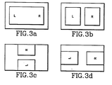
- the foreground scene comprises the letters L and R on a solid color panel and the background scene is a vertical surface of a contrasting solid color.
- the foreground scene may be split by dividing the panel along a vertical line and separating the two halves of the panel in the horizontal direction (FIG. 3(b)).
- Another effect that can be performed is to rotate the foreground scene, e.g. through 90 degrees, about an axis that is perpendicular to the viewing plane and extends through the center of the picture.
- the result that is obtained depends on whether the split effect was a source-space effect or a target-space effect. If the split were a source-space effect, the picture would appear as if the split had been performed before the rotation (FIG. 3(d), whereas if the split were a target-space effect, the picture would appear as if the split had been performed after the rotation (FIG 3(c)).
- an output video signal is derived from an input video signal representative of an input scene by writing the input video signal into a frame buffer, generating a sequence of address words, comparing each address word with a reference word that defines a predetermined location of the input scene, modifying at least those address words that define locations of the input scene having a selected spatial relationship with said predetermined location by combining each of them with an offset word, whereby a modified sequence of address words is generated, and using the modified sequence of address words to read the video signal from the frame buffer.
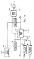
- the video channel and the key channel are illustrated as single blocks 38 and 40, and the address limit detector is not shown.
- the FIG. 4 reverse transform system differs from that of FIG. 2 by incorporating a split/mirror logic block 60 that is connected to the output of the reverse address generator.
- the split/mirror logic block Through use of the split/mirror logic block, the scene represented by the input video signal can be divided along a horizontal axis and/or a vertical axis (in the source space) and/or a mirror image of the part of the input scene on one side of the horizontal axis and/or the vertical axis (in the source space) can be created on the opposite side of the horizontal axis and/or the vertical axis.
- the split/mirror logic block 60 receives the sequence of reverse addresses (X ⁇ , Y ⁇ ) and modifies the X ⁇ and Y ⁇ portions of the addresses.
- Identical circuits 60X and 60Y act independently on the X ⁇ and Y ⁇ portions of the reverse addresses.
- the circuit that acts on the X ⁇ portion of the reverse addresses is shown in FIG. 5. For the sake of definiteness with respect to terms of orientation and position, it will be assumed in the following description of the operation of the FIG. 5 circuit that the reverse transform system is set up so that a spatial transformation is not performed by the reverse address generator.
- the FIG. 5 circuit comprises a split/mirror position register 62 in which a reference position word is stored and left and right offset registers 64 and 66 in which offset words are stored.
- the reference position word defines the position in the input scene of the vertical axis with reference to which the mirror or split effect is to take place.
- a comparator 68 compares the input address word X ⁇ with the content of the register 62 and controls a switch 72 in dependence on the result of the com parison for selecting which of the registers 64 and 66 is connected to the ALU 70.
- the ALU 70 For each input address word X ⁇ that it receives, the ALU computes a corresponding output address word X ⁇ .
- the ALU 70 is able to perform two arithmetic operations, namely add the value of X ⁇ to the value of the word stored in the offset register selected by the switch 72, or subtract the value of X ⁇ from the value of the word stored in the selected offset register.
- the nature of the arithmetic operation depends on commands received by the ALU from the operator interface.
- the operator interface also enables the operator to determine the words stored in the registers 62, 64 and 66. By appropriate selection of the arithmetic operations and the values of the words stored in the registers, the operator is able to cause the split/mirror logic circuit shown in FIG. 5 to implement each of the following effects:
- the ALU responds to the output of the comparator 68 indicating that the input word X ⁇ represents the left side of the input scene by adding zero to the input word and providing an output word X ⁇ that is the same as the input word.
- the input word is passed unchanged, and the left side of the output scene is the same as the left side of the input scene.
- a value 100 had been stored in the register 64, the output word would have been 100 greater than the input word. Consequently, when the output word is used to read the video signal from the frame buffer, the left side of the input scene appears in the output scene displaced by 100 pixels to the left.
- the ALU 70 responds to the output of the comparator indicating that the address word X ⁇ represents the left side of the screen by subtracting the address word from the offset word and providing an output address word X ⁇ that is greater than the input address word and decreases as the value of the input address word increases.
- the distribution of the value of X ⁇ over the left side of the output address space (X, Y) is a mirror image of that for the right side of the input address space (U, V), and the left side of the output scene is a reflection of the right side of the input scene. If, on the other hand, the value 920 had been stored in the register 64, the output word would have been 200 greater than in the previous case, and therefore the left side of the output scene would have been a reflection of the portion of the input scene that is to the right of the split/mirror axis by 200 pixels.
- the input scene passes unchanged if the ALU operation is addition and the offset value is zero, and there is a horizontal split if the ALU operation is addition and the offset value is non-zero, whereas there is a simple reflection if the ALU operation is subtraction and the offset value is twice the value of the split/mirror position word and there is reflection plus horizontal split if the ALU operation is subtraction and the offset value is different from twice the value of the split/mirror position word.
- the output address word X ⁇ is applied to one input of a comparator 73 which receives as its other input the content of the register 62.
- the output of the comparator 73 is applied to a split blanking logic circuit 74.
- the split blanking logic circuit also receives the output of the comparator 68. If one of X ⁇ and X ⁇ is smaller than the value stored in the register 62 and the other of X ⁇ and X ⁇ is greater than the value stored in the register 62 (which can only happen if there is a horizontal split, with or without the mirror effect), this indicates that the output address word X ⁇ represents a location that is between the two sides of the split, and a split blanking signal is asserted.
- split blanking signal is not asserted.
- the split blanking output of the split blanking logic circuit 74 is connected to an AND gate 76, which receives an on/off signal from the operator interface, indicating whether or not split blanking is to be invoked.
- split blanking is to be invoked and the split blanking signal is asserted, the split blanking signal is applied by the AND gate to the blankers of the video and key channels and the output signals of the interpolators are blanked, whereas if split blanking is not to be invoked, the split blanking signal is inhibited by the AND gate 76 and the output signals of the interpolators are not blanked.
- the operation of the split/mirror logic circuit 60Y is analogous to that of the circuit 60X.
- the circuit 60Y receives input address word Y ⁇ and generates output address words Y ⁇ that are such that vertical split and/or mirror effects can be provided.
Landscapes
- Engineering & Computer Science (AREA)
- Multimedia (AREA)
- Signal Processing (AREA)
- Studio Circuits (AREA)
- Image Processing (AREA)
- Television Signal Processing For Recording (AREA)
Applications Claiming Priority (2)
| Application Number | Priority Date | Filing Date | Title |
|---|---|---|---|
| US06/922,589 US4689682A (en) | 1986-10-24 | 1986-10-24 | Method and apparatus for carrying out television special effects |
| US922589 | 1992-07-30 |
Publications (3)
| Publication Number | Publication Date |
|---|---|
| EP0264963A2 true EP0264963A2 (de) | 1988-04-27 |
| EP0264963A3 EP0264963A3 (de) | 1991-01-30 |
| EP0264963B1 EP0264963B1 (de) | 1994-03-30 |
Family
ID=25447275
Family Applications (1)
| Application Number | Title | Priority Date | Filing Date |
|---|---|---|---|
| EP87115623A Expired - Lifetime EP0264963B1 (de) | 1986-10-24 | 1987-10-23 | Verfahren und Anordnung zur Erzeugung von Fernsehtrickeffekten |
Country Status (6)
| Country | Link |
|---|---|
| US (1) | US4689682A (de) |
| EP (1) | EP0264963B1 (de) |
| JP (1) | JPH0834561B2 (de) |
| AU (1) | AU591813B2 (de) |
| CA (1) | CA1251854A (de) |
| DE (1) | DE3789485T2 (de) |
Families Citing this family (6)
| Publication number | Priority date | Publication date | Assignee | Title |
|---|---|---|---|---|
| US4956872A (en) * | 1986-10-31 | 1990-09-11 | Canon Kabushiki Kaisha | Image processing apparatus capable of random mosaic and/or oil-painting-like processing |
| US4831447A (en) * | 1987-11-16 | 1989-05-16 | The Grass Valley Group, Inc. | Method and apparatus for anti-aliasing an image boundary during video special effects |
| US5231475A (en) * | 1990-02-16 | 1993-07-27 | Videotek, Inc. | Method and apparatus for generating video signal representing controllable color matte |
| US5448301A (en) * | 1994-05-25 | 1995-09-05 | The Grass Valley Group, Inc. | Programmable video transformation rendering method and apparatus |
| JP3705447B2 (ja) * | 1994-11-17 | 2005-10-12 | 株式会社ルネサステクノロジ | 画像処理方法および画像処理装置 |
| US20050231643A1 (en) * | 2004-03-26 | 2005-10-20 | Ross Video Limited | Method, system and device for real-time non-linear video transformations |
Family Cites Families (13)
| Publication number | Priority date | Publication date | Assignee | Title |
|---|---|---|---|---|
| US3944731A (en) * | 1975-03-03 | 1976-03-16 | Sarkes Tarzian, Inc. | Video special effects generator |
| JPS5345120A (en) * | 1976-10-05 | 1978-04-22 | Tokyo Hoso:Kk | Video special effect device |
| GB1595964A (en) * | 1977-03-17 | 1981-08-19 | Micro Consultants Ltd Tv | Special effects generator |
| US4631750A (en) * | 1980-04-11 | 1986-12-23 | Ampex Corporation | Method and system for spacially transforming images |
| US4432009A (en) * | 1981-03-24 | 1984-02-14 | Rca Corporation | Video pre-filtering in phantom raster generating apparatus |
| WO1982003712A1 (en) * | 1981-04-10 | 1982-10-28 | Gabriel Steven Allen | Controller for system for spatially transforming images |
| JPS58500635A (ja) * | 1981-04-10 | 1983-04-21 | アムペツクス コ−ポレ−シヨン | 映像を空間的にトランスフオ−ムするシステム |
| US4602286A (en) * | 1982-01-15 | 1986-07-22 | Quantel Limited | Video processing for composite images |
| GB8306339D0 (en) * | 1982-03-19 | 1983-04-13 | Quantel Ltd | Video processing systems |
| US4463372A (en) * | 1982-03-24 | 1984-07-31 | Ampex Corporation | Spatial transformation system including key signal generator |
| US4568981A (en) * | 1983-04-08 | 1986-02-04 | Ampex Corporation | Font recall system and method of operation |
| JP2526857B2 (ja) * | 1984-12-27 | 1996-08-21 | ソニー株式会社 | 画像信号変換方法 |
| JP2751927B2 (ja) * | 1985-04-12 | 1998-05-18 | アムペツクス コ−ポレ−シヨン | ビデオ特殊効果生成装置 |
-
1986
- 1986-10-24 US US06/922,589 patent/US4689682A/en not_active Expired - Lifetime
-
1987
- 1987-10-20 CA CA000549757A patent/CA1251854A/en not_active Expired
- 1987-10-23 EP EP87115623A patent/EP0264963B1/de not_active Expired - Lifetime
- 1987-10-23 AU AU80080/87A patent/AU591813B2/en not_active Ceased
- 1987-10-23 DE DE3789485T patent/DE3789485T2/de not_active Expired - Fee Related
- 1987-10-24 JP JP62269151A patent/JPH0834561B2/ja not_active Expired - Lifetime
Also Published As
| Publication number | Publication date |
|---|---|
| US4689682A (en) | 1987-08-25 |
| CA1251854A (en) | 1989-03-28 |
| AU8008087A (en) | 1988-04-28 |
| AU591813B2 (en) | 1989-12-14 |
| DE3789485D1 (de) | 1994-05-05 |
| EP0264963B1 (de) | 1994-03-30 |
| JPH0834561B2 (ja) | 1996-03-29 |
| JPS63122372A (ja) | 1988-05-26 |
| DE3789485T2 (de) | 1994-10-13 |
| EP0264963A3 (de) | 1991-01-30 |
Similar Documents
| Publication | Publication Date | Title |
|---|---|---|
| US4875097A (en) | Perspective processing of a video signal | |
| US4689681A (en) | Television special effects system | |
| US4563703A (en) | Video processing systems | |
| US5313275A (en) | Chroma processor including a look-up table or memory | |
| US4851912A (en) | Apparatus for combining video signals | |
| US4700232A (en) | Interpolator for television special effects system | |
| US5233332A (en) | Page turning effect generating apparatus | |
| JPH01870A (ja) | テレビジヨン特殊効果装置 | |
| JPS61148488A (ja) | デイスプレイ制御装置 | |
| GB2254517A (en) | Video signal colour correction | |
| US4879597A (en) | Processing of video image signals | |
| EP0264963B1 (de) | Verfahren und Anordnung zur Erzeugung von Fernsehtrickeffekten | |
| US5742353A (en) | Image processing apparatus | |
| US5327177A (en) | Method of and apparatus for processing a shaped video signal to add a simulated shadow | |
| EP0264964B1 (de) | Verfahren und Anordnung zur Verarbeitung eines Videosignals | |
| US4918530A (en) | Processing of video image signals | |
| JP2709356B2 (ja) | 画像処理方法 | |
| US5592196A (en) | Picture data processing apparatus | |
| CN114647467B (zh) | 水印更新方法、装置、系统及存储介质 | |
| EP0268359B1 (de) | Verfahren und Vorrichtung zur Verarbeitung von Fernsehbildsignalen | |
| JP3382170B2 (ja) | マルチウインドウ画像表示装置 | |
| WO1992005664A1 (en) | Video image composition | |
| JP2506897B2 (ja) | マルチウィンドウ表示制御方式 | |
| JPH03297285A (ja) | 画像合成装置及び画像合成装置用比較器 | |
| JPS63296089A (ja) | 画像表示装置 |
Legal Events
| Date | Code | Title | Description |
|---|---|---|---|
| PUAI | Public reference made under article 153(3) epc to a published international application that has entered the european phase |
Free format text: ORIGINAL CODE: 0009012 |
|
| AK | Designated contracting states |
Kind code of ref document: A2 Designated state(s): DE FR GB |
|
| PUAL | Search report despatched |
Free format text: ORIGINAL CODE: 0009013 |
|
| AK | Designated contracting states |
Kind code of ref document: A3 Designated state(s): DE FR GB |
|
| 17P | Request for examination filed |
Effective date: 19910208 |
|
| 17Q | First examination report despatched |
Effective date: 19921014 |
|
| GRAA | (expected) grant |
Free format text: ORIGINAL CODE: 0009210 |
|
| AK | Designated contracting states |
Kind code of ref document: B1 Designated state(s): DE FR GB |
|
| PG25 | Lapsed in a contracting state [announced via postgrant information from national office to epo] |
Ref country code: FR Effective date: 19940330 |
|
| REF | Corresponds to: |
Ref document number: 3789485 Country of ref document: DE Date of ref document: 19940505 |
|
| EN | Fr: translation not filed | ||
| PLBE | No opposition filed within time limit |
Free format text: ORIGINAL CODE: 0009261 |
|
| STAA | Information on the status of an ep patent application or granted ep patent |
Free format text: STATUS: NO OPPOSITION FILED WITHIN TIME LIMIT |
|
| 26N | No opposition filed | ||
| PGFP | Annual fee paid to national office [announced via postgrant information from national office to epo] |
Ref country code: DE Payment date: 19990930 Year of fee payment: 13 |
|
| PG25 | Lapsed in a contracting state [announced via postgrant information from national office to epo] |
Ref country code: DE Free format text: LAPSE BECAUSE OF NON-PAYMENT OF DUE FEES Effective date: 20010801 |
|
| REG | Reference to a national code |
Ref country code: GB Ref legal event code: IF02 |
|
| PGFP | Annual fee paid to national office [announced via postgrant information from national office to epo] |
Ref country code: GB Payment date: 20060829 Year of fee payment: 20 |
|
| REG | Reference to a national code |
Ref country code: GB Ref legal event code: PE20 |
|
| PG25 | Lapsed in a contracting state [announced via postgrant information from national office to epo] |
Ref country code: GB Free format text: LAPSE BECAUSE OF EXPIRATION OF PROTECTION Effective date: 20071022 |