EP0265000A1 - Schalldämpfende Lüftungsvorrichtung, insbesondere für einen Lüftungsdurchgang einer Wand - Google Patents
Schalldämpfende Lüftungsvorrichtung, insbesondere für einen Lüftungsdurchgang einer Wand Download PDFInfo
- Publication number
- EP0265000A1 EP0265000A1 EP87201922A EP87201922A EP0265000A1 EP 0265000 A1 EP0265000 A1 EP 0265000A1 EP 87201922 A EP87201922 A EP 87201922A EP 87201922 A EP87201922 A EP 87201922A EP 0265000 A1 EP0265000 A1 EP 0265000A1
- Authority
- EP
- European Patent Office
- Prior art keywords
- inner pipe
- silencing
- enclosed space
- passage
- casing
- Prior art date
- Legal status (The legal status is an assumption and is not a legal conclusion. Google has not performed a legal analysis and makes no representation as to the accuracy of the status listed.)
- Granted
Links
Images
Classifications
-
- F—MECHANICAL ENGINEERING; LIGHTING; HEATING; WEAPONS; BLASTING
- F01—MACHINES OR ENGINES IN GENERAL; ENGINE PLANTS IN GENERAL; STEAM ENGINES
- F01N—GAS-FLOW SILENCERS OR EXHAUST APPARATUS FOR MACHINES OR ENGINES IN GENERAL; GAS-FLOW SILENCERS OR EXHAUST APPARATUS FOR INTERNAL-COMBUSTION ENGINES
- F01N1/00—Silencing apparatus characterised by method of silencing
- F01N1/003—Silencing apparatus characterised by method of silencing by using dead chambers communicating with exhaust gas flow passages
- F01N1/006—Silencing apparatus characterised by method of silencing by using dead chambers communicating with exhaust gas flow passages comprising at least one perforated tube extending from inlet to outlet of the silencer
-
- F—MECHANICAL ENGINEERING; LIGHTING; HEATING; WEAPONS; BLASTING
- F01—MACHINES OR ENGINES IN GENERAL; ENGINE PLANTS IN GENERAL; STEAM ENGINES
- F01N—GAS-FLOW SILENCERS OR EXHAUST APPARATUS FOR MACHINES OR ENGINES IN GENERAL; GAS-FLOW SILENCERS OR EXHAUST APPARATUS FOR INTERNAL-COMBUSTION ENGINES
- F01N1/00—Silencing apparatus characterised by method of silencing
- F01N1/02—Silencing apparatus characterised by method of silencing by using resonance
-
- F—MECHANICAL ENGINEERING; LIGHTING; HEATING; WEAPONS; BLASTING
- F01—MACHINES OR ENGINES IN GENERAL; ENGINE PLANTS IN GENERAL; STEAM ENGINES
- F01N—GAS-FLOW SILENCERS OR EXHAUST APPARATUS FOR MACHINES OR ENGINES IN GENERAL; GAS-FLOW SILENCERS OR EXHAUST APPARATUS FOR INTERNAL-COMBUSTION ENGINES
- F01N1/00—Silencing apparatus characterised by method of silencing
- F01N1/02—Silencing apparatus characterised by method of silencing by using resonance
- F01N1/023—Helmholtz resonators
-
- F—MECHANICAL ENGINEERING; LIGHTING; HEATING; WEAPONS; BLASTING
- F24—HEATING; RANGES; VENTILATING
- F24F—AIR-CONDITIONING; AIR-HUMIDIFICATION; VENTILATION; USE OF AIR CURRENTS FOR SCREENING
- F24F13/00—Details common to, or for air-conditioning, air-humidification, ventilation or use of air currents for screening
- F24F13/24—Means for preventing or suppressing noise
-
- G—PHYSICS
- G10—MUSICAL INSTRUMENTS; ACOUSTICS
- G10K—SOUND-PRODUCING DEVICES; METHODS OR DEVICES FOR PROTECTING AGAINST, OR FOR DAMPING, NOISE OR OTHER ACOUSTIC WAVES IN GENERAL; ACOUSTICS NOT OTHERWISE PROVIDED FOR
- G10K11/00—Methods or devices for transmitting, conducting or directing sound in general; Methods or devices for protecting against, or for damping, noise or other acoustic waves in general
- G10K11/16—Methods or devices for protecting against, or for damping, noise or other acoustic waves in general
- G10K11/172—Methods or devices for protecting against, or for damping, noise or other acoustic waves in general using resonance effects
-
- F—MECHANICAL ENGINEERING; LIGHTING; HEATING; WEAPONS; BLASTING
- F01—MACHINES OR ENGINES IN GENERAL; ENGINE PLANTS IN GENERAL; STEAM ENGINES
- F01N—GAS-FLOW SILENCERS OR EXHAUST APPARATUS FOR MACHINES OR ENGINES IN GENERAL; GAS-FLOW SILENCERS OR EXHAUST APPARATUS FOR INTERNAL-COMBUSTION ENGINES
- F01N2490/00—Structure, disposition or shape of gas-chambers
- F01N2490/15—Plurality of resonance or dead chambers
-
- F—MECHANICAL ENGINEERING; LIGHTING; HEATING; WEAPONS; BLASTING
- F01—MACHINES OR ENGINES IN GENERAL; ENGINE PLANTS IN GENERAL; STEAM ENGINES
- F01N—GAS-FLOW SILENCERS OR EXHAUST APPARATUS FOR MACHINES OR ENGINES IN GENERAL; GAS-FLOW SILENCERS OR EXHAUST APPARATUS FOR INTERNAL-COMBUSTION ENGINES
- F01N2490/00—Structure, disposition or shape of gas-chambers
- F01N2490/15—Plurality of resonance or dead chambers
- F01N2490/155—Plurality of resonance or dead chambers being disposed one after the other in flow direction
-
- F—MECHANICAL ENGINEERING; LIGHTING; HEATING; WEAPONS; BLASTING
- F01—MACHINES OR ENGINES IN GENERAL; ENGINE PLANTS IN GENERAL; STEAM ENGINES
- F01N—GAS-FLOW SILENCERS OR EXHAUST APPARATUS FOR MACHINES OR ENGINES IN GENERAL; GAS-FLOW SILENCERS OR EXHAUST APPARATUS FOR INTERNAL-COMBUSTION ENGINES
- F01N2490/00—Structure, disposition or shape of gas-chambers
- F01N2490/20—Chambers being formed inside the exhaust pipe without enlargement of the cross section of the pipe, e.g. resonance chambers
Definitions
- This invention relates to a silencing ventilating device, in particular for a ventilating passage in a wall or partition and provided with a tubular casing and at least one tubular inner pipe having at least one opening in its wall, connecting a continuous ventilating passage to an enclosed space formed by transverse baffles originating from the inner pipe and/or the casing.
- silencing ventilating devices are known from the brochure Gebr. Trox GmbH "Silencers, silencing coulisses, sound; absorbing elements, series M.X.Z.”, 1979, page No. 5-SD2, pages 1, 2, 16, 17, and have the form of duct silencers, round silencers and silencing coulisses.
- the silencing effect of these devices is based on sound-absorbing material filling up the enclosed space. For that reason, said material, at the location of the partition between the enclosed space and the continuous ventilating passage, is surrounded by a maximally porous envelope, e.g. a wall with a multiplicity of perforations therein or a glass fabric.
- a maximally porous envelope e.g. a wall with a multiplicity of perforations therein or a glass fabric.
- the damping to be obtained with these known silencing ventilating devices is insufficient with respect to the sound-absorbing effect to be achieved, or will be insufficient at the anticipated higher sound insulation standards to be set by the authorities.
- a silencing ventilating device in which the inner pipe is shut off at its ends by means of transverse end baffles, according to a further embodiment of the present invention, that the inner pipe contains further transverse baffles which divide the inner pipe into various compartments, each having a different volume.
- the number of frequency ranges in which optimum damping according to the present invention can be obtained can be increased still further where, in a silencing ventilating device in which at least two inner pipes of different diameter are present and the innermost inner pipe is shut off at its ends by transverse end baffles, and further transverse end baffles are provided at the ends adjacent inner pipe and possibly between two adjacent inner pipes, according to a further embodiment of the present invention, there is provided within the enclosed spaces at least one further transverse baffle subdividing an enclosed space into compartments of different volume. In this manner, it is possible to arrange Helmholtz resonators having different frequency ranges within the innermost inner pipe, between the casing and the outermost inner pipe and/or between any further inner pipes, that may be present.
- the desired silencing effect it may be preferable in certain cases to amplify the frequency range and take a slight weakening of the silencing effect into the bargain.
- This can be realized, according to a further embodiment of the present invention, when at least one of the enclosed spaces is filled up at least partly, with sound absorbing material. Even in that case, due to the Helmholz resonator effect created according to the present invention a more effective silencing effect is obtained than is possible with silencing ventilating devices of the prior art.
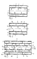
- Fig. 1 is a longitudinal section of a silencing ventilating device composed of a tubular casing 1 and a tubular inner pipe 2 arranged concentrically within casing 1 in a manner not shown. Both casing 1 and inner pipe 2 may have any cross-sectional configuration, with a preference for a circular cross-section.
- the ends of inner pipe 2 are shut off by a transverse baffle 3, thereby producing an enclosed space 4.
- a free, annular ventilating passage 5 Between inner pipe 2 and casing 1 there is provided a free, annular ventilating passage 5.
- Within inner pipe 2 there are provided a plurality of holes in the form of saw cuts 6.
- the lengths and widths of saw cuts 6 connecting the ventilating passage 5 to the enclosed space 4 are chosen in such a manner that the total area of passage thereof renders the enclosed space a Helmholtz resonator tuned to a predetermined frequency so that a highly effective damping in the range around said frequency is obtained.
- the enclosed space may be filled at least partly with sound-absorbing material.
- the silencing ventilating device shown in Fig. 2 comprises a casing 11 and an inner pipe 12. At the ends, there are provided between casing 11 and inner pipe 12 annular transverse baffles 13, thereby creating between the casing and the pipe a space 14 that is enclosed with respect to the surroundings.
- the internal passage of the inner pipe forms the free ventilating duct 15.
- Inner pipe 12 has holes in its wall in the form of saw cuts 16, forming an open connection between duct 15 and the enclosed space. 14.
- the latter is divided into two compartments 14a, 14b by an annular transverse baffle 17, with the lengths and widths of the saw cuts 16 be ing chosen for each compartment in such a manner that two Helmholtz resonators are produced, each tuned to a different damping frequency range.
- sound-absorbing material can also be provided in the compartments 14a, 14b.
- Fig. 3 shows a silencing ventilating device composed of a casing 21 and two inner pipes, the innermost being designated by reference numeral 22 and the outermost by 23.
- transverse baff1es 24 provided at the ends of inner pipe 22, there is created an enclosed space 25 which is subdivided into two compartments 25a, 25b by a further transverse baffle 26.
- Transverse baffles 24 and 27 leave the annular space between the two inner pipes 22, 23 clear, thereby creating a free ventilating passage 31.
- the latter is in open communication with the enclosed compartments 25a, 25b, 28a, 28b and 28c by means of saw cuts 32 in inner pipe 22 and saw cuts 33 in inner pipe 23.
- the lengths and widths of the various saw cuts 32, 33, in relation to the compartments to which they provide access, are chosen in such a manner that each compartment forms a Helmholtz resonator tuned to a different frequency.
- one or a plurality 20 of compartments can be filled, if desired, with sound-absorbing material.
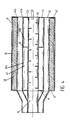
- Fig. 4 shows a silencing ventilating device which may serve as a wall passage for a wall-mounted heater.
- a casing 41 and three inner pipes, the innermost being designated at 42a, the central one at 42b, the outermost at 42c.
- Inner pipe 42a is open at its ends thus forming a first free passage 43.
- annular transverse baffles 44 there are provided at the end annular transverse baffles 44, thereby forming an enclosed space 45, which is subdivided into two compartments 45a, 45b by a further annular transverse baffle 46. Openings in the form of saw cuts 50 again bring the free passage 43 in communication with compartments 45a, 45b.
- annular transverse baffles 47 Between casing 41 and inner pipe 42c, there are provided annular transverse baffles 47 at the ends, thereby forming an enclosed space 48.
- This enclosed annular space 48 accommodates heat-insulating material 49 so as to form an insulation between the wall passage for conducting hot gases and the wall or partition itself.
- the enclosed space 48 can again be subdivided into compartments by annular transverse baffles and can be brought in communication with the free passage 52 by openings in inner pipe 42c.
- An adapter 51 is provided for connection to a known double concentric supply and discharge pipe for fresh air and combustion gases.
- the perforations may have any other form than that of a saw cut, which is preferred.
- the only important feature is that the total area thereof is tuned, in the manner of a Helmholtz resonator, to the volume of the compartment to which access is provided from a ventilating passage.
- the number of enclosed spaces can be increased by providing one or a plurality of pairs of additional inner pipes.
- the design of the silencing ventilating device at the two ends has not been desdribed herein. These may be provided in a known manner with mounting means, seepage covers, insect grids and shut off means. Although a circular cross section is preferred, any other form, in particular a square or rectangular form is also possible. Although the casing and inner pipe are shown herein as single-piece elements, it is also p ossible to compose these of sections, e.g. having the size of one compartment.
Landscapes
- Engineering & Computer Science (AREA)
- Chemical & Material Sciences (AREA)
- Combustion & Propulsion (AREA)
- Mechanical Engineering (AREA)
- General Engineering & Computer Science (AREA)
- Physics & Mathematics (AREA)
- Acoustics & Sound (AREA)
- Multimedia (AREA)
- Building Environments (AREA)
- Ventilation (AREA)
- Soundproofing, Sound Blocking, And Sound Damping (AREA)
Applications Claiming Priority (2)
| Application Number | Priority Date | Filing Date | Title |
|---|---|---|---|
| NL8602537 | 1986-10-09 | ||
| NL8602537A NL8602537A (nl) | 1986-10-09 | 1986-10-09 | Geluiddempende ventilatieinrichting, in het bijzonder voor een ventilatiedoorvoer in een muur of wand. |
Publications (2)
| Publication Number | Publication Date |
|---|---|
| EP0265000A1 true EP0265000A1 (de) | 1988-04-27 |
| EP0265000B1 EP0265000B1 (de) | 1992-04-01 |
Family
ID=19848649
Family Applications (1)
| Application Number | Title | Priority Date | Filing Date |
|---|---|---|---|
| EP87201922A Expired - Lifetime EP0265000B1 (de) | 1986-10-09 | 1987-10-08 | Schalldämpfende Lüftungsvorrichtung, insbesondere für einen Lüftungsdurchgang einer Wand |
Country Status (3)
| Country | Link |
|---|---|
| EP (1) | EP0265000B1 (de) |
| DE (1) | DE3777942D1 (de) |
| NL (1) | NL8602537A (de) |
Cited By (8)
| Publication number | Priority date | Publication date | Assignee | Title |
|---|---|---|---|---|
| WO1992015088A1 (en) * | 1991-02-21 | 1992-09-03 | Lotus Cars Limited | Method and apparatus for attenuating acoustic vibrations in a medium |
| GB2365066A (en) * | 2000-07-28 | 2002-02-13 | Draftex Ind Ltd | Noise attenuation arrangements for pressurised-gas conduits |
| NL1029327C2 (nl) * | 2005-06-23 | 2006-12-28 | Alusta Natuurlijke Ventilatiet | Geluiddempende en ventilerende muurdoorvoer. |
| GB2457298A (en) * | 2008-02-09 | 2009-08-12 | Owen Ronald Clingan | Ventilation system having one or more baffles mounted in a duct to attenuate sound |
| US8272475B2 (en) | 2008-04-30 | 2012-09-25 | Metso Paper, Inc. | Sound attenuator for low frequencies, method for manufacturing sound attenuator for low frequencies and system for attenuating low frequencies for example in air-conditioning ducts of paper mills |
| WO2019073641A1 (ja) * | 2017-10-12 | 2019-04-18 | 富士ゼロックス株式会社 | 通気管路および装置 |
| US20190120414A1 (en) * | 2017-10-23 | 2019-04-25 | Hamilton Sundstrand Corporation | Duct assembly having internal noise reduction features, thermal insulation and leak detection |
| SE1850154A1 (en) * | 2018-02-13 | 2019-08-14 | Creo Dynamics Ab | Acoustic damper for a gas duct system |
Families Citing this family (2)
| Publication number | Priority date | Publication date | Assignee | Title |
|---|---|---|---|---|
| CN104344149A (zh) * | 2014-09-12 | 2015-02-11 | 徐东海 | 具有缓流装置的水管 |
| CN112629002B (zh) * | 2021-01-06 | 2022-02-18 | 滁州市新华建筑安装有限责任公司 | 一种建筑工程暖通气流消声器 |
Citations (5)
| Publication number | Priority date | Publication date | Assignee | Title |
|---|---|---|---|---|
| GB610000A (en) * | 1946-03-27 | 1948-10-08 | Arnold Freedman | Improvements in and relating to silencers for gaseous currents |
| US2580564A (en) * | 1948-06-28 | 1952-01-01 | Arvin Ind Inc | Muffler with tuned side branch silencing chambers |
| FR1283147A (fr) * | 1960-03-11 | 1962-01-27 | Colchester Woods | Silencieux |
| FR2321590A2 (fr) * | 1975-08-22 | 1977-03-18 | Plessy Fernand | Perfectionnements aux silencieux pour moteur |
| US4167986A (en) * | 1978-03-13 | 1979-09-18 | Adco, Ltd. | Fluid stream silencing device |
Family Cites Families (1)
| Publication number | Priority date | Publication date | Assignee | Title |
|---|---|---|---|---|
| US2299112A (en) * | 1939-10-30 | 1942-10-20 | Robert C Brown Jr | Acoustic filter |
-
1986
- 1986-10-09 NL NL8602537A patent/NL8602537A/nl not_active Application Discontinuation
-
1987
- 1987-10-08 DE DE8787201922T patent/DE3777942D1/de not_active Expired - Fee Related
- 1987-10-08 EP EP87201922A patent/EP0265000B1/de not_active Expired - Lifetime
Patent Citations (5)
| Publication number | Priority date | Publication date | Assignee | Title |
|---|---|---|---|---|
| GB610000A (en) * | 1946-03-27 | 1948-10-08 | Arnold Freedman | Improvements in and relating to silencers for gaseous currents |
| US2580564A (en) * | 1948-06-28 | 1952-01-01 | Arvin Ind Inc | Muffler with tuned side branch silencing chambers |
| FR1283147A (fr) * | 1960-03-11 | 1962-01-27 | Colchester Woods | Silencieux |
| FR2321590A2 (fr) * | 1975-08-22 | 1977-03-18 | Plessy Fernand | Perfectionnements aux silencieux pour moteur |
| US4167986A (en) * | 1978-03-13 | 1979-09-18 | Adco, Ltd. | Fluid stream silencing device |
Non-Patent Citations (1)
| Title |
|---|
| BROCHURE GEBR. TROX GmbH, no. 5, SD 2, 1979, pages 1,2,16,17; "Geluiddempers, geluiddempende koelissen, geluidabsorptie elementen, serie M.X.Z" * |
Cited By (12)
| Publication number | Priority date | Publication date | Assignee | Title |
|---|---|---|---|---|
| WO1992015088A1 (en) * | 1991-02-21 | 1992-09-03 | Lotus Cars Limited | Method and apparatus for attenuating acoustic vibrations in a medium |
| GB2365066A (en) * | 2000-07-28 | 2002-02-13 | Draftex Ind Ltd | Noise attenuation arrangements for pressurised-gas conduits |
| GB2365066B (en) * | 2000-07-28 | 2005-01-26 | Draftex Ind Ltd | Noise attenuation arrangements for pressurised-gas conduits |
| NL1029327C2 (nl) * | 2005-06-23 | 2006-12-28 | Alusta Natuurlijke Ventilatiet | Geluiddempende en ventilerende muurdoorvoer. |
| GB2457298A (en) * | 2008-02-09 | 2009-08-12 | Owen Ronald Clingan | Ventilation system having one or more baffles mounted in a duct to attenuate sound |
| US8272475B2 (en) | 2008-04-30 | 2012-09-25 | Metso Paper, Inc. | Sound attenuator for low frequencies, method for manufacturing sound attenuator for low frequencies and system for attenuating low frequencies for example in air-conditioning ducts of paper mills |
| WO2019073641A1 (ja) * | 2017-10-12 | 2019-04-18 | 富士ゼロックス株式会社 | 通気管路および装置 |
| JP2021012222A (ja) * | 2017-10-12 | 2021-02-04 | 富士ゼロックス株式会社 | 通気管路および装置 |
| US11543152B2 (en) | 2017-10-12 | 2023-01-03 | Fujifilm Business Innovation Corp. | Ventilation duct line assembly and apparatus |
| US20190120414A1 (en) * | 2017-10-23 | 2019-04-25 | Hamilton Sundstrand Corporation | Duct assembly having internal noise reduction features, thermal insulation and leak detection |
| SE1850154A1 (en) * | 2018-02-13 | 2019-08-14 | Creo Dynamics Ab | Acoustic damper for a gas duct system |
| SE544189C2 (en) * | 2018-02-13 | 2022-02-22 | Faurecia Creo Ab | Acoustic damper for a gas duct system |
Also Published As
| Publication number | Publication date |
|---|---|
| NL8602537A (nl) | 1988-05-02 |
| EP0265000B1 (de) | 1992-04-01 |
| DE3777942D1 (de) | 1992-05-07 |
Similar Documents
| Publication | Publication Date | Title |
|---|---|---|
| EP0219218B1 (de) | Schalldämpfer | |
| EP1356193B1 (de) | Vorrichtung zur verbesserten lärmdämpfung in einem absorptionsdämpfer einer brennkraftmaschine | |
| US4231447A (en) | Multi-layer acoustic linings | |
| US4150732A (en) | Resonant cavity devices for reducing noise within a duct in the presence of a gaseous fluid | |
| US4236597A (en) | Sound-absorbing device, especially for damping of noises expanding in air ducts | |
| US4116303A (en) | Exhaust muffler | |
| US2323955A (en) | Resonance unit | |
| CA1042809A (en) | Free flow sound attenuating device and method of using | |
| EP0265000A1 (de) | Schalldämpfende Lüftungsvorrichtung, insbesondere für einen Lüftungsdurchgang einer Wand | |
| US4164266A (en) | Exhaust gas muffler | |
| US6415887B1 (en) | Refractive wave muffler | |
| ES2214547T3 (es) | Silenciador. | |
| US4930597A (en) | Noise attenuation apparatus | |
| GB748053A (en) | Improvements in or relating to exhaust silencers for internal combustion engines | |
| JP3664675B2 (ja) | 消音換気装置 | |
| JPH0271300A (ja) | 吸音体とそれを利用した吸音ダクト | |
| JP3653763B2 (ja) | 消音器 | |
| US3263771A (en) | Sound absorbing pipe lining having packing with different densities | |
| EP1117965B1 (de) | Reaktiver schalldämpfer für lüftungskanäle und dessen verwendung | |
| SE515765C2 (sv) | Dubbelväggig konstruktion och sätt att tillverka densamma | |
| JP2004094065A (ja) | 騒音低減装置および排気装置 | |
| US5004068A (en) | Muffler | |
| CN210977634U (zh) | 双出气多管迷路结构排气消声器 | |
| JPS6233935Y2 (de) | ||
| EP4414611A1 (de) | Zusammenbau eines biomasse-heizsystems und einer schalldämpfenden vorrichtung |
Legal Events
| Date | Code | Title | Description |
|---|---|---|---|
| PUAI | Public reference made under article 153(3) epc to a published international application that has entered the european phase |
Free format text: ORIGINAL CODE: 0009012 |
|
| AK | Designated contracting states |
Kind code of ref document: A1 Designated state(s): BE DE FR NL |
|
| 17P | Request for examination filed |
Effective date: 19880621 |
|
| 17Q | First examination report despatched |
Effective date: 19891016 |
|
| GRAA | (expected) grant |
Free format text: ORIGINAL CODE: 0009210 |
|
| AK | Designated contracting states |
Kind code of ref document: B1 Designated state(s): BE DE FR NL |
|
| REF | Corresponds to: |
Ref document number: 3777942 Country of ref document: DE Date of ref document: 19920507 |
|
| ET | Fr: translation filed | ||
| PLBE | No opposition filed within time limit |
Free format text: ORIGINAL CODE: 0009261 |
|
| STAA | Information on the status of an ep patent application or granted ep patent |
Free format text: STATUS: NO OPPOSITION FILED WITHIN TIME LIMIT |
|
| 26N | No opposition filed | ||
| PGFP | Annual fee paid to national office [announced via postgrant information from national office to epo] |
Ref country code: FR Payment date: 20031028 Year of fee payment: 17 |
|
| PGFP | Annual fee paid to national office [announced via postgrant information from national office to epo] |
Ref country code: DE Payment date: 20031107 Year of fee payment: 17 |
|
| PG25 | Lapsed in a contracting state [announced via postgrant information from national office to epo] |
Ref country code: DE Free format text: LAPSE BECAUSE OF NON-PAYMENT OF DUE FEES Effective date: 20050503 |
|
| PG25 | Lapsed in a contracting state [announced via postgrant information from national office to epo] |
Ref country code: FR Free format text: LAPSE BECAUSE OF NON-PAYMENT OF DUE FEES Effective date: 20050630 |
|
| REG | Reference to a national code |
Ref country code: FR Ref legal event code: ST |
|
| NLS | Nl: assignments of ep-patents |
Owner name: ALUSTA NATUURLIJKE VENTILATIETECHNIEK B.V. Effective date: 20050607 |
|
| PGFP | Annual fee paid to national office [announced via postgrant information from national office to epo] |
Ref country code: NL Payment date: 20061017 Year of fee payment: 20 |
|
| PGFP | Annual fee paid to national office [announced via postgrant information from national office to epo] |
Ref country code: BE Payment date: 20061120 Year of fee payment: 20 |
|
| NLV7 | Nl: ceased due to reaching the maximum lifetime of a patent |
Effective date: 20071008 |
|
| BE20 | Be: patent expired |
Owner name: *ZWAAN ADRIANUS JACOBUS Effective date: 20071008 |
|
| PG25 | Lapsed in a contracting state [announced via postgrant information from national office to epo] |
Ref country code: NL Free format text: LAPSE BECAUSE OF EXPIRATION OF PROTECTION Effective date: 20071008 |