EP0265014A2 - Gestell für Moped - Google Patents
Gestell für Moped Download PDFInfo
- Publication number
- EP0265014A2 EP0265014A2 EP87201976A EP87201976A EP0265014A2 EP 0265014 A2 EP0265014 A2 EP 0265014A2 EP 87201976 A EP87201976 A EP 87201976A EP 87201976 A EP87201976 A EP 87201976A EP 0265014 A2 EP0265014 A2 EP 0265014A2
- Authority
- EP
- European Patent Office
- Prior art keywords
- frame
- moped
- footrest
- horizontal
- slanting
- Prior art date
- Legal status (The legal status is an assumption and is not a legal conclusion. Google has not performed a legal analysis and makes no representation as to the accuracy of the status listed.)
- Granted
Links
Images


Classifications
-
- B—PERFORMING OPERATIONS; TRANSPORTING
- B62—LAND VEHICLES FOR TRAVELLING OTHERWISE THAN ON RAILS
- B62K—CYCLES; CYCLE FRAMES; CYCLE STEERING DEVICES; RIDER-OPERATED TERMINAL CONTROLS SPECIALLY ADAPTED FOR CYCLES; CYCLE AXLE SUSPENSIONS; CYCLE SIDECARS, FORECARS, OR THE LIKE
- B62K11/00—Motorcycles, engine-assisted cycles or motor scooters with one or two wheels
- B62K11/02—Frames
- B62K11/04—Frames characterised by the engine being between front and rear wheels
- B62K11/06—Frames characterised by the engine being between front and rear wheels the frame being of single-beam type
-
- B—PERFORMING OPERATIONS; TRANSPORTING
- B62—LAND VEHICLES FOR TRAVELLING OTHERWISE THAN ON RAILS
- B62J—CYCLE SADDLES OR SEATS; AUXILIARY DEVICES OR ACCESSORIES SPECIALLY ADAPTED TO CYCLES AND NOT OTHERWISE PROVIDED FOR, e.g. ARTICLE CARRIERS OR CYCLE PROTECTORS
- B62J25/00—Foot-rests; Knee grips; Passenger hand-grips
- B62J25/04—Floor-type foot rests
-
- B—PERFORMING OPERATIONS; TRANSPORTING
- B62—LAND VEHICLES FOR TRAVELLING OTHERWISE THAN ON RAILS
- B62M—RIDER PROPULSION OF WHEELED VEHICLES OR SLEDGES; POWERED PROPULSION OF SLEDGES OR SINGLE-TRACK CYCLES; TRANSMISSIONS SPECIALLY ADAPTED FOR SUCH VEHICLES
- B62M7/00—Motorcycles characterised by position of motor or engine
- B62M7/02—Motorcycles characterised by position of motor or engine with engine between front and rear wheels
- B62M7/06—Motorcycles characterised by position of motor or engine with engine between front and rear wheels directly under the saddle or seat
-
- F—MECHANICAL ENGINEERING; LIGHTING; HEATING; WEAPONS; BLASTING
- F02—COMBUSTION ENGINES; HOT-GAS OR COMBUSTION-PRODUCT ENGINE PLANTS
- F02B—INTERNAL-COMBUSTION PISTON ENGINES; COMBUSTION ENGINES IN GENERAL
- F02B61/00—Adaptations of engines for driving vehicles or for driving propellers; Combinations of engines with gearing
- F02B61/02—Adaptations of engines for driving vehicles or for driving propellers; Combinations of engines with gearing for driving cycles
Definitions
- the present invention relates to improvements to the frames of motorcycles, particularly mopeds. Two aspects of such frames are affected by the invention, which provides an integrated solution for them.
- the first of these aspects concerns the luggage carrier.
- the luggage carrier As all moped users and motorcycle users in general know, the fact that the standard-equipment luggage carrier is always positioned behind the saddle, and thus out of continuous view, makes it impossible for the cyclist to check that the objects contained in the carrier remain stably anchored, and that this often causes unease and worry in the cyclist or motorcyclist. It would be desiderable for the luggage carrier to be able to be placed in a sufficiently visible position, provided this does not negatively affect the driving of the vehicle. It is for example wholly incorrect to anchor it to the steering assembly (handlebars or front fork) inasmuch as the weight of the luggage, even though limited, affects driving conditions.
- the second of the said aspects is the increasing importance taken on by the small footboard/s on which the feet can be rested when the cyclist in not pedalling (and also on fixed footrests, as are adopted on nearly all mopeds, except the so-called "sports" types).
- the utility of the characteristic in question and the resulting market demand for it are due to the fact that in the position mentioned the cyclist is better protected against bad weather; in this regard it is far better to have a single footboard allowing the feet to be kept together than two small, separate footboards on the sides of the frame. Both solutions exist on the market, but not a single footboard of sufficient width and lenght at a limited height off the ground.
- the characteristics mentioned at the outset as being desiderable are obtained by embodying a moped in which a beam-type frame features a central portion having substantially horizontal development, and of the correct width, at one end of which there is connected a front portion that carries the articulation of the front-wheel fork and the other end of which the said central portion extends to become an upward-slanting portion (the slant angle being as small as possible) which continues to below the centre of the saddle.
- the upper surface of the horizontally developing portion of the frame acts as a footboard, while the analogue of the slanted portion acts as a luggage carrier, being integrated by suitable containing and securing elements.
- the luggage thus has a very baricentric and low position, which enhances stability and also means that it can be controlled visually and also manually from the cycling position.
- the luggage carrier thus positioned inside the external bulk of vehicle also lends itself well to acting as a support surface for the cyclist's crash-helmet when the vehicle is parked.
- the presence of the saddle and its supports can assist in defining elements for anchoring the crash-helmet to the vehicle.
- the upper surface of the slanted portion of the frame can further be used as an alternative footrest, allowing lady-cyclists to ride in the position they normally adopt when they are wearing a skirt and are seated (Figure 7).
- the said requisites are: - ease of dismounting from the frame in its central area; thus a maximum height of 35-37 cm; - correct heighwise positioning of the pedal axes (if pedals are present), since if too low they are dangerous and if too high inconvenient and also correct longitudinal positioning of the pedal axes (several centimetres further forward from the narrow end of the saddle, as in bycicles proper); - possibility of elastic rear suspension, which makes it more difficult to keep to the aforesaid 35-37 cm in that these values are desiderable with the vehicle unloaded; - appropriate arrangement of other important members, such as the engine and fuel tank.
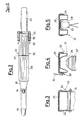
- the moped comprises a frame indicated overall by 10, which extends from the axis A-A of the steering to the vertical B-B of the centre of the saddle.
- the frame can be tubular, overlaid with plastic parts or, more conveniently, can be made of sheet material, as illustrated hereinafter, but in any case with a generally rectilinear overall section the height of which is less than the width.
- the frame features a substantially horizontal central portion 11 which extends to become an upwards-slanting rear portion 12. At its front end the part 11 features a short part 13 connecting to the hub 14 of the steering: the steering itself will provide for handlebars shown diagramatically at 16 and a known suspension arrangement for a wheel 15.
- the central part 11, with overlay 25 made of a suitable material, represents the footrest which is sufficiently wide and, by virtue of the possible architecture of the engine (as will be seen hereinafter) sufficiently low.
- the rear portion 12, overlaid with the aforesaid element 25 or other equivalent separate member, is used as luggage carrier.
- the area can be limited forwardly by the protusion 32, fixed, removable or tippable, and provided with a series of lateral hooks 33 adapted to anchor pass-through members 34 for securing the luggage.
- supports 21 for the saddle 22 such supports advantageously having the form of tubular elements secured to the frame by bolting, welding or sundry articulations if it is wished that they be foldable.
- the two supports 21 can also form rear luggage-containment elements, when the luggage is voluminous as in the case of bags, etc. and crash-helmets.
- the rear mudguard 23 can with advantage be secured in overhung manner.
- a motor-rearwheel assembly shown diagrammatically and indicated overall by 18.
- the engine cylinder is indicated by 27, the wheel by 29 and the pedals by 30;
- the numeral 31 indicates the longitudinal arm of the assembly accepting the pedal-wheel and the engine-wheel trasmissions.
- the configuration of the frame is such that it can typically accept a rear wheel that is not excessively large, in particular of diameter midway between that of the scooter wheels and that of high-wheel moped wheels (for example 14 ⁇ ).
- the embodiment of the supension of the frame can be of different configurations; the drawings exemplify an embodiment with a central elestic member 19 or with two lateral elstic members 20.
- the frame as illustrated can to advantage be made of sheet or plate material, in particular with two half-shells welded laterally at 24, and can have in its upper portion the previously mentioned overlay 25.
- Figure 4 shows how a hollow 26 can be formed in the portion 12 of the frame to accept the bulk of the engine 27 forming part of the assembly 18.
- the power pack positioning shown in the drawings which uses the space created by the slant of the rear section of the frame and by the hollow formed in the lower face, is the key-element for satisfying the criteria of characteristics as set out earlier herein inasmuch as below the horizontal section of the frame there remains, practically in isolation, the bulk of the pedal system, which can thus assume its most suitable position both lenghtwise and heighwise; in addition, the horizontal section of the frame can be of the pre-set height (35 ⁇ 37 cm. off the ground).
- the engine-rearwheel architecture as described is not the only one compatible with the proposed frame; however, it is probably the one that avoids compromise with regard to the desired characteristics.
- the frame can be provided in its lower portion with a seating 28 for accepting the wheel.
- the frame 10 can constitute a fuel-tank.
- the fuel-tank cap 35 will be disposed proximally to the higher end of the slanted portion 12.
Landscapes
- Engineering & Computer Science (AREA)
- Mechanical Engineering (AREA)
- Chemical & Material Sciences (AREA)
- Combustion & Propulsion (AREA)
- Transportation (AREA)
- General Engineering & Computer Science (AREA)
- Cleaning Implements For Floors, Carpets, Furniture, Walls, And The Like (AREA)
- Automatic Cycles, And Cycles In General (AREA)
- Table Devices Or Equipment (AREA)
- Stringed Musical Instruments (AREA)
- Wing Frames And Configurations (AREA)
- Special Wing (AREA)
- Steering Devices For Bicycles And Motorcycles (AREA)
- Handcart (AREA)
- Axle Suspensions And Sidecars For Cycles (AREA)
Priority Applications (1)
| Application Number | Priority Date | Filing Date | Title |
|---|---|---|---|
| AT87201976T ATE70505T1 (de) | 1986-10-24 | 1987-10-15 | Gestell fuer moped. |
Applications Claiming Priority (2)
| Application Number | Priority Date | Filing Date | Title |
|---|---|---|---|
| IT8623480U IT208259Z2 (it) | 1986-10-24 | 1986-10-24 | Ciclomotore a telaio perfezionato. |
| IT2348086U | 1986-10-24 |
Publications (3)
| Publication Number | Publication Date |
|---|---|
| EP0265014A2 true EP0265014A2 (de) | 1988-04-27 |
| EP0265014A3 EP0265014A3 (en) | 1988-07-27 |
| EP0265014B1 EP0265014B1 (de) | 1991-12-18 |
Family
ID=11207471
Family Applications (1)
| Application Number | Title | Priority Date | Filing Date |
|---|---|---|---|
| EP87201976A Expired - Lifetime EP0265014B1 (de) | 1986-10-24 | 1987-10-15 | Gestell für Moped |
Country Status (6)
| Country | Link |
|---|---|
| US (1) | US4799567A (de) |
| EP (1) | EP0265014B1 (de) |
| AT (1) | ATE70505T1 (de) |
| DE (1) | DE3775336D1 (de) |
| ES (1) | ES2027686T3 (de) |
| IT (1) | IT208259Z2 (de) |
Cited By (1)
| Publication number | Priority date | Publication date | Assignee | Title |
|---|---|---|---|---|
| EP1459973A3 (de) * | 2003-03-19 | 2008-07-16 | HONDA MOTOR CO., Ltd. | Fahrzeug mit abgesenktem Boden |
Families Citing this family (3)
| Publication number | Priority date | Publication date | Assignee | Title |
|---|---|---|---|---|
| US5036937A (en) * | 1989-08-04 | 1991-08-06 | Yamaha Hatsudoki Kabushiki Kaisha | Exercise vehicle |
| US6964313B2 (en) * | 2003-01-23 | 2005-11-15 | Biketoo, Incorporated | Personal transport vehicle, such as a bicycle |
| FR2958259B1 (fr) * | 2010-04-01 | 2014-04-11 | Matra Mfg & Services | Deux-roues electrique |
Family Cites Families (10)
| Publication number | Priority date | Publication date | Assignee | Title |
|---|---|---|---|---|
| GB190917233A (en) * | 1909-07-24 | 1910-06-16 | Arthur William Wall | An Improved Frame for Motor Cycles. |
| US1371783A (en) * | 1919-06-04 | 1921-03-15 | Goudard Maurice | Motorcycle |
| US2545142A (en) * | 1946-04-24 | 1951-03-13 | Motom G M B H | Frame for two or three wheeled vehicles |
| NL6501568A (de) * | 1964-02-11 | 1965-08-12 | ||
| US4169512A (en) * | 1976-06-01 | 1979-10-02 | Honda Giken Kogyo Kabushiki Kaisha | Power unit swinging type motor cycles |
| DE2831289A1 (de) * | 1978-07-17 | 1980-01-31 | Ruffer Hans Georg | Fahrrad- und rollerkombinationsfahrzeug mit einer ladeplattform |
| JPS57121380U (de) * | 1981-01-23 | 1982-07-28 | ||
| JPS5836784A (ja) * | 1981-08-26 | 1983-03-03 | 本田技研工業株式会社 | 軽車両のフロア構造 |
| US4451057A (en) * | 1982-01-25 | 1984-05-29 | Lawson Louis L | Foot-rest device for motorcycles |
| US4715465A (en) * | 1985-01-17 | 1987-12-29 | Honda Giken Kogyo Kabushiki Kaisha | Body construction for motor scooter vehicles |
-
1986
- 1986-10-24 IT IT8623480U patent/IT208259Z2/it active
-
1987
- 1987-10-15 ES ES198787201976T patent/ES2027686T3/es not_active Expired - Lifetime
- 1987-10-15 EP EP87201976A patent/EP0265014B1/de not_active Expired - Lifetime
- 1987-10-15 AT AT87201976T patent/ATE70505T1/de not_active IP Right Cessation
- 1987-10-15 DE DE87201976T patent/DE3775336D1/de not_active Expired - Lifetime
- 1987-10-19 US US07/109,765 patent/US4799567A/en not_active Expired - Fee Related
Cited By (1)
| Publication number | Priority date | Publication date | Assignee | Title |
|---|---|---|---|---|
| EP1459973A3 (de) * | 2003-03-19 | 2008-07-16 | HONDA MOTOR CO., Ltd. | Fahrzeug mit abgesenktem Boden |
Also Published As
| Publication number | Publication date |
|---|---|
| US4799567A (en) | 1989-01-24 |
| EP0265014B1 (de) | 1991-12-18 |
| IT8623480V0 (it) | 1986-10-24 |
| EP0265014A3 (en) | 1988-07-27 |
| IT208259Z2 (it) | 1988-04-29 |
| ATE70505T1 (de) | 1992-01-15 |
| ES2027686T3 (es) | 1992-06-16 |
| DE3775336D1 (en) | 1992-01-30 |
Similar Documents
| Publication | Publication Date | Title |
|---|---|---|
| US4660854A (en) | Frame construction for motorcycles | |
| US6152473A (en) | Folding collapsible baby tricycle | |
| CA1077079A (en) | Convertible tricycle | |
| US4334589A (en) | Two-wheeled motorcycle with combined frame and cowling structure | |
| NZ203181A (en) | Four wheeled motorcycle | |
| US4691930A (en) | Wheeled vehicle | |
| US4763913A (en) | Bicycle/scooter combination | |
| US5470092A (en) | Bicycle frame | |
| EP0265014B1 (de) | Gestell für Moped | |
| US4579190A (en) | Power unit swing type motorcycle | |
| US5904361A (en) | Removable mudguard for a bicycle | |
| US5284351A (en) | Recumbent bicycle | |
| US4548419A (en) | Motorcycle sidecar | |
| JPS6247754B2 (de) | ||
| US5297808A (en) | Sidecar for bicycles | |
| US5248158A (en) | Sidecar for bicycles | |
| JP3585191B2 (ja) | 自動二輪車の補助ステップ装置 | |
| JP3575216B2 (ja) | 自動二輪車のリヤフェンダ装置 | |
| GB2144687A (en) | Improvements in bicycle frames and bicycles | |
| JP2681507B2 (ja) | 鞍乗型車両のフートレスト装置 | |
| JP2917358B2 (ja) | 自動二輪車のセンタスタンドストッパ構造 | |
| WO1999029562A1 (en) | Motorcycle | |
| US20260048808A1 (en) | Electric motorcycle and frame assembly for motorcycle | |
| JP2601239B2 (ja) | 不整地走行用鞍乗型四輪車のステアリングシャフト支持構造 | |
| JP4430271B2 (ja) | 小型車両のフロントバスケットおよび補機取付け構造 |
Legal Events
| Date | Code | Title | Description |
|---|---|---|---|
| PUAI | Public reference made under article 153(3) epc to a published international application that has entered the european phase |
Free format text: ORIGINAL CODE: 0009012 |
|
| AK | Designated contracting states |
Kind code of ref document: A2 Designated state(s): AT BE CH DE ES FR GB GR IT LI NL |
|
| PUAL | Search report despatched |
Free format text: ORIGINAL CODE: 0009013 |
|
| RHK1 | Main classification (correction) |
Ipc: B62J 25/00 |
|
| AK | Designated contracting states |
Kind code of ref document: A3 Designated state(s): AT BE CH DE ES FR GB GR IT LI NL |
|
| 17P | Request for examination filed |
Effective date: 19890104 |
|
| 17Q | First examination report despatched |
Effective date: 19900327 |
|
| GRAA | (expected) grant |
Free format text: ORIGINAL CODE: 0009210 |
|
| AK | Designated contracting states |
Kind code of ref document: B1 Designated state(s): AT BE CH DE ES FR GB GR IT LI NL |
|
| PG25 | Lapsed in a contracting state [announced via postgrant information from national office to epo] |
Ref country code: NL Effective date: 19911218 Ref country code: LI Effective date: 19911218 Ref country code: GR Free format text: LAPSE BECAUSE OF FAILURE TO SUBMIT A TRANSLATION OF THE DESCRIPTION OR TO PAY THE FEE WITHIN THE PRESCRIBED TIME-LIMIT Effective date: 19911218 Ref country code: CH Effective date: 19911218 Ref country code: BE Effective date: 19911218 Ref country code: AT Effective date: 19911218 |
|
| REF | Corresponds to: |
Ref document number: 70505 Country of ref document: AT Date of ref document: 19920115 Kind code of ref document: T |
|
| REF | Corresponds to: |
Ref document number: 3775336 Country of ref document: DE Date of ref document: 19920130 |
|
| ITF | It: translation for a ep patent filed | ||
| REG | Reference to a national code |
Ref country code: CH Ref legal event code: PL |
|
| ET | Fr: translation filed | ||
| NLV1 | Nl: lapsed or annulled due to failure to fulfill the requirements of art. 29p and 29m of the patents act | ||
| REG | Reference to a national code |
Ref country code: ES Ref legal event code: FG2A Ref document number: 2027686 Country of ref document: ES Kind code of ref document: T3 |
|
| PG25 | Lapsed in a contracting state [announced via postgrant information from national office to epo] |
Ref country code: GB Effective date: 19921015 |
|
| PLBE | No opposition filed within time limit |
Free format text: ORIGINAL CODE: 0009261 |
|
| STAA | Information on the status of an ep patent application or granted ep patent |
Free format text: STATUS: NO OPPOSITION FILED WITHIN TIME LIMIT |
|
| 26N | No opposition filed | ||
| GBPC | Gb: european patent ceased through non-payment of renewal fee |
Effective date: 19921015 |
|
| PGFP | Annual fee paid to national office [announced via postgrant information from national office to epo] |
Ref country code: FR Payment date: 19951006 Year of fee payment: 9 |
|
| PGFP | Annual fee paid to national office [announced via postgrant information from national office to epo] |
Ref country code: DE Payment date: 19951025 Year of fee payment: 9 |
|
| PGFP | Annual fee paid to national office [announced via postgrant information from national office to epo] |
Ref country code: ES Payment date: 19961007 Year of fee payment: 10 |
|
| PG25 | Lapsed in a contracting state [announced via postgrant information from national office to epo] |
Ref country code: FR Effective date: 19970630 |
|
| PG25 | Lapsed in a contracting state [announced via postgrant information from national office to epo] |
Ref country code: DE Effective date: 19970701 |
|
| REG | Reference to a national code |
Ref country code: FR Ref legal event code: ST |
|
| PG25 | Lapsed in a contracting state [announced via postgrant information from national office to epo] |
Ref country code: ES Free format text: LAPSE BECAUSE OF THE APPLICANT RENOUNCES Effective date: 19971016 |
|
| REG | Reference to a national code |
Ref country code: ES Ref legal event code: FD2A Effective date: 20001009 |
|
| PG25 | Lapsed in a contracting state [announced via postgrant information from national office to epo] |
Ref country code: IT Free format text: LAPSE BECAUSE OF NON-PAYMENT OF DUE FEES;WARNING: LAPSES OF ITALIAN PATENTS WITH EFFECTIVE DATE BEFORE 2007 MAY HAVE OCCURRED AT ANY TIME BEFORE 2007. THE CORRECT EFFECTIVE DATE MAY BE DIFFERENT FROM THE ONE RECORDED. Effective date: 20051015 |