EP0265123B1 - Kühlsystem für Mehrkammertransporte - Google Patents
Kühlsystem für Mehrkammertransporte Download PDFInfo
- Publication number
- EP0265123B1 EP0265123B1 EP87308904A EP87308904A EP0265123B1 EP 0265123 B1 EP0265123 B1 EP 0265123B1 EP 87308904 A EP87308904 A EP 87308904A EP 87308904 A EP87308904 A EP 87308904A EP 0265123 B1 EP0265123 B1 EP 0265123B1
- Authority
- EP
- European Patent Office
- Prior art keywords
- remote
- unit
- evaporator
- host unit
- host
- Prior art date
- Legal status (The legal status is an assumption and is not a legal conclusion. Google has not performed a legal analysis and makes no representation as to the accuracy of the status listed.)
- Expired - Lifetime
Links
Images


Classifications
-
- B—PERFORMING OPERATIONS; TRANSPORTING
- B60—VEHICLES IN GENERAL
- B60H—ARRANGEMENTS OF HEATING, COOLING, VENTILATING OR OTHER AIR-TREATING DEVICES SPECIALLY ADAPTED FOR PASSENGER OR GOODS SPACES OF VEHICLES
- B60H1/00—Heating, cooling or ventilating devices
- B60H1/32—Cooling devices
- B60H1/3204—Cooling devices using compression
- B60H1/3232—Cooling devices using compression particularly adapted for load transporting vehicles
-
- F—MECHANICAL ENGINEERING; LIGHTING; HEATING; WEAPONS; BLASTING
- F25—REFRIGERATION OR COOLING; COMBINED HEATING AND REFRIGERATION SYSTEMS; HEAT PUMP SYSTEMS; MANUFACTURE OR STORAGE OF ICE; LIQUEFACTION SOLIDIFICATION OF GASES
- F25B—REFRIGERATION MACHINES, PLANTS OR SYSTEMS; COMBINED HEATING AND REFRIGERATION SYSTEMS; HEAT PUMP SYSTEMS
- F25B13/00—Compression machines, plants or systems, with reversible cycle
-
- F—MECHANICAL ENGINEERING; LIGHTING; HEATING; WEAPONS; BLASTING
- F25—REFRIGERATION OR COOLING; COMBINED HEATING AND REFRIGERATION SYSTEMS; HEAT PUMP SYSTEMS; MANUFACTURE OR STORAGE OF ICE; LIQUEFACTION SOLIDIFICATION OF GASES
- F25B—REFRIGERATION MACHINES, PLANTS OR SYSTEMS; COMBINED HEATING AND REFRIGERATION SYSTEMS; HEAT PUMP SYSTEMS
- F25B47/00—Arrangements for preventing or removing deposits or corrosion, not provided for in another subclass
- F25B47/02—Defrosting cycles
- F25B47/022—Defrosting cycles hot gas defrosting
-
- F—MECHANICAL ENGINEERING; LIGHTING; HEATING; WEAPONS; BLASTING
- F25—REFRIGERATION OR COOLING; COMBINED HEATING AND REFRIGERATION SYSTEMS; HEAT PUMP SYSTEMS; MANUFACTURE OR STORAGE OF ICE; LIQUEFACTION SOLIDIFICATION OF GASES
- F25B—REFRIGERATION MACHINES, PLANTS OR SYSTEMS; COMBINED HEATING AND REFRIGERATION SYSTEMS; HEAT PUMP SYSTEMS
- F25B5/00—Compression machines, plants or systems, with several evaporator circuits, e.g. for varying refrigerating capacity
-
- F—MECHANICAL ENGINEERING; LIGHTING; HEATING; WEAPONS; BLASTING
- F25—REFRIGERATION OR COOLING; COMBINED HEATING AND REFRIGERATION SYSTEMS; HEAT PUMP SYSTEMS; MANUFACTURE OR STORAGE OF ICE; LIQUEFACTION SOLIDIFICATION OF GASES
- F25D—REFRIGERATORS; COLD ROOMS; ICE-BOXES; COOLING OR FREEZING APPARATUS NOT OTHERWISE PROVIDED FOR
- F25D11/00—Self-contained movable devices, e.g. domestic refrigerators
- F25D11/003—Transport containers
-
- B—PERFORMING OPERATIONS; TRANSPORTING
- B60—VEHICLES IN GENERAL
- B60H—ARRANGEMENTS OF HEATING, COOLING, VENTILATING OR OTHER AIR-TREATING DEVICES SPECIALLY ADAPTED FOR PASSENGER OR GOODS SPACES OF VEHICLES
- B60H1/00—Heating, cooling or ventilating devices
- B60H1/00642—Control systems or circuits; Control members or indication devices for heating, cooling or ventilating devices
- B60H1/00814—Control systems or circuits characterised by their output, for controlling particular components of the heating, cooling or ventilating installation
- B60H1/00878—Control systems or circuits characterised by their output, for controlling particular components of the heating, cooling or ventilating installation the components being temperature regulating devices
- B60H2001/00961—Control systems or circuits characterised by their output, for controlling particular components of the heating, cooling or ventilating installation the components being temperature regulating devices comprising means for defrosting outside heat exchangers
-
- F—MECHANICAL ENGINEERING; LIGHTING; HEATING; WEAPONS; BLASTING
- F25—REFRIGERATION OR COOLING; COMBINED HEATING AND REFRIGERATION SYSTEMS; HEAT PUMP SYSTEMS; MANUFACTURE OR STORAGE OF ICE; LIQUEFACTION SOLIDIFICATION OF GASES
- F25B—REFRIGERATION MACHINES, PLANTS OR SYSTEMS; COMBINED HEATING AND REFRIGERATION SYSTEMS; HEAT PUMP SYSTEMS
- F25B2313/00—Compression machines, plants or systems with reversible cycle not otherwise provided for
- F25B2313/009—Compression machines, plants or systems with reversible cycle not otherwise provided for indoor unit in circulation with outdoor unit in first operation mode, indoor unit in circulation with an other heat exchanger in second operation mode or outdoor unit in circulation with an other heat exchanger in third operation mode
-
- F—MECHANICAL ENGINEERING; LIGHTING; HEATING; WEAPONS; BLASTING
- F25—REFRIGERATION OR COOLING; COMBINED HEATING AND REFRIGERATION SYSTEMS; HEAT PUMP SYSTEMS; MANUFACTURE OR STORAGE OF ICE; LIQUEFACTION SOLIDIFICATION OF GASES
- F25B—REFRIGERATION MACHINES, PLANTS OR SYSTEMS; COMBINED HEATING AND REFRIGERATION SYSTEMS; HEAT PUMP SYSTEMS
- F25B2313/00—Compression machines, plants or systems with reversible cycle not otherwise provided for
- F25B2313/023—Compression machines, plants or systems with reversible cycle not otherwise provided for using multiple indoor units
-
- F—MECHANICAL ENGINEERING; LIGHTING; HEATING; WEAPONS; BLASTING
- F25—REFRIGERATION OR COOLING; COMBINED HEATING AND REFRIGERATION SYSTEMS; HEAT PUMP SYSTEMS; MANUFACTURE OR STORAGE OF ICE; LIQUEFACTION SOLIDIFICATION OF GASES
- F25B—REFRIGERATION MACHINES, PLANTS OR SYSTEMS; COMBINED HEATING AND REFRIGERATION SYSTEMS; HEAT PUMP SYSTEMS
- F25B2313/00—Compression machines, plants or systems with reversible cycle not otherwise provided for
- F25B2313/029—Control issues
- F25B2313/0292—Control issues related to reversing valves
-
- F—MECHANICAL ENGINEERING; LIGHTING; HEATING; WEAPONS; BLASTING
- F25—REFRIGERATION OR COOLING; COMBINED HEATING AND REFRIGERATION SYSTEMS; HEAT PUMP SYSTEMS; MANUFACTURE OR STORAGE OF ICE; LIQUEFACTION SOLIDIFICATION OF GASES
- F25B—REFRIGERATION MACHINES, PLANTS OR SYSTEMS; COMBINED HEATING AND REFRIGERATION SYSTEMS; HEAT PUMP SYSTEMS
- F25B2400/00—Component parts or details not otherwise provided for in this subclass
- F25B2400/05—Compression system with heat exchange between particular parts of the system
-
- F—MECHANICAL ENGINEERING; LIGHTING; HEATING; WEAPONS; BLASTING
- F25—REFRIGERATION OR COOLING; COMBINED HEATING AND REFRIGERATION SYSTEMS; HEAT PUMP SYSTEMS; MANUFACTURE OR STORAGE OF ICE; LIQUEFACTION SOLIDIFICATION OF GASES
- F25B—REFRIGERATION MACHINES, PLANTS OR SYSTEMS; COMBINED HEATING AND REFRIGERATION SYSTEMS; HEAT PUMP SYSTEMS
- F25B2400/00—Component parts or details not otherwise provided for in this subclass
- F25B2400/16—Receivers
-
- F—MECHANICAL ENGINEERING; LIGHTING; HEATING; WEAPONS; BLASTING
- F25—REFRIGERATION OR COOLING; COMBINED HEATING AND REFRIGERATION SYSTEMS; HEAT PUMP SYSTEMS; MANUFACTURE OR STORAGE OF ICE; LIQUEFACTION SOLIDIFICATION OF GASES
- F25B—REFRIGERATION MACHINES, PLANTS OR SYSTEMS; COMBINED HEATING AND REFRIGERATION SYSTEMS; HEAT PUMP SYSTEMS
- F25B2600/00—Control issues
- F25B2600/25—Control of valves
- F25B2600/2523—Receiver valves
-
- F—MECHANICAL ENGINEERING; LIGHTING; HEATING; WEAPONS; BLASTING
- F25—REFRIGERATION OR COOLING; COMBINED HEATING AND REFRIGERATION SYSTEMS; HEAT PUMP SYSTEMS; MANUFACTURE OR STORAGE OF ICE; LIQUEFACTION SOLIDIFICATION OF GASES
- F25B—REFRIGERATION MACHINES, PLANTS OR SYSTEMS; COMBINED HEATING AND REFRIGERATION SYSTEMS; HEAT PUMP SYSTEMS
- F25B2700/00—Sensing or detecting of parameters; Sensors therefor
- F25B2700/19—Pressures
- F25B2700/193—Pressures of the compressor
- F25B2700/1933—Suction pressures
Definitions
- the invention relates to a method of controlling the temperature in each of two or more separate compartments of a compartmentalized transport refrigeration system, and to a compartmentalized transport refrigeration system with air temperature control.
- Transport refrigeration systems often utilize multi-temperature control for controlling the air temperature in two or more separate compartments of a multi-temperature trailer.
- a trailer may carry a frozen load in the front compartment, which is controlled by the main refrigeration unit called the host unit, and fresh loads in the one or more remote compartments, which are controlled by remote evaporators.
- Some prior art systems utilize electric heaters supplied by an alternator to provide heat for a remote compartment.
- the dedicated prime mover such as a Diesel engine, is operated at the higher of two normal operating speeds used at various times during the process of controlling the temperatures of the loads. For example, the higher of the two speeds may be 2200 RPM and the lower may be 1400 RPM.
- Hot gas from the host unit has been used to defrost the remote evaporator, but the use of hot gas to heat the remote evaporator has had disadvantages. For example, ambient temperatures below 40 degrees F limit the heating capacity of the remote evaporator.
- Remote evaporators have also suffered disadvantages not related to heating. For example, in systems which utilize a three-way valve to select host heating and cooling modes, the remote evaporator cannot go into a cooling mode when the host unit is in a heating mode, because the three-way valve is switched from a cooling position to a heating position by a pilot solenoid when the host unit requires heat.
- GB-A-988,874 discloses a relationalized truck refrigeration system having a "freezer" compartment and a "cooler” compartment.
- the cooler compartment contains both an evaporator and a heater, with the heater receiving all of the hot refrigerant gas from a compressor when the cooler requires heat to maintain a predetermined temperature in the cooler compartment.
- a manual defrost operation may also initiate the same action.
- the freezer compartment contains an evaporator which can be defrosted by closing a manually operated swtich which results in directing hot refrigerant gas into the evaporator.
- Refrigeration controls are interlocked such that the first compartment to go into a heating or defrosting mode locks out the other from initiating a heating or defrosting mode. One does not have a preference over the other. Also the freezer can go into a defrost mode while the cooler is in a cooling mode.
- the invention consists in a compartmentalized transport refrigeration system, a method of controlling the temperature in a first compartment of a trailer to a first set point via a host refrigeration unit having a compressor, condenser, receiver, and evaporator, and the temperature of a second trailer compartment to a second set point via a remote evaporator having liquid, hot gas and suction lines selectively connectable to the host refrigeration unit, characterized by the the step of preventing the host unit from going into a heating mode when the host unit requires heat to maintain the first set point, in response to the remote unit requiring cooling to maintain the second set point while the host unit is controlling to a first set point which is below a predetermined value, terminating a host unit heating mode at any time when the remote unit requires cooling, and directing all discharge gas from the compressors to the remote evaporator when the remove evaporator requires heat to maintain the second set point, while the host unit is not in a heating mode.
- the invention also consists in a compartmentalized transport refrigeration system, including a trailer having a first compartment, a host unit for controlling the air temperature of said first compartment via heating, cooling and null modes, said host unit comprising a closed fluid circuit which includes a compressor, condenser, receiver, evaporator, and liquid, hot gas and suction lines, a second compartment in said trailer, a remote evaporator for controlling the air temperature of said second compartment via heating, cooling, and null modes, said remote evaporator including liquid, hot gas and suction lines connected to the liquid, hot gas and suction lines, respectively, of said host unit, first means for selectively enabling and blocking fluid flow from the high pressure side of said compressor to said condenser when said host unit is in a cooling mode, second, third and fourth means for respectively and selectively enabling and blocking fluid flow between said remote liquid, hot gas and suction lines and said host unit, one-way by-pass means interconnecting the suction line of said remote evaporator and the receiver of said host unit, and control means
- the host unit When the host unit is not in a heating mode, all of the discharge gas from the compressor is made available for use by the remote evaporator unit during certain operating conditions. Thus, the heating and cooling capabilities of the remote evaporator unit are significantly improved.
- the host unit is prevented from going into a heating mode when: (a) the set point of the host unit is below a predetermined temperature, called the lockout temperature, which may be -9.44 degrees C (15 degrees F), for example, and (b) the remote evaporator unit is in a cooling mode.
- the lockout temperature which may be -9.44 degrees C (15 degrees F)
- the remote evaporator unit is in a cooling mode.
- the cooling requirements of the remote unit are satisfied without the possibility of the host unit going into a heating mode.
- the remote unit requires heat while the host unit is in a cooling mode, all of the hot compressor gas is directed to the remote evaporator unit by preventing the hot gas from entering the condenser, and by directing the output of the remote evaporator to the receiver instead of to the accumulator.
- more liquid refrigerant is forced from the receiver and the heating capability of the remote evaporator unit is greatly enhanced.
- a second embodiment of the invention is similar to the first, except a liquid line control is provided in the host unit. Further, the controls are interlocked such that the host liquid line control cannot close unless the remote unit is cooling, insuring that refrigerant is always being circulated through the compressor.
- the second embodiment thus allows the host unit to cycle between cooling and null modes while the remote unit is cooling.
- Trailer 10 includes a front compartment 12 which has its air temperature controlled by the main or host refrigeration unit 14 which is mounted on the vertical front surface 16 of the trailer 10.
- the front compartment 12 is normally used for frozen loads, with a typical set temperature being -23 degrees C (-10 degrees F).
- Vertical partition or wall 18 insulatingly separates the front compartment 12 from one or more rear compartments, with a single rear compartment 20 being shown for purposes of example.
- Rear compartment 20 has its air temperature controlled by a remote refrigeration unit which includes a remote control box 22 mounted on the front surface 16 of the trailer 10, and one or more remote evaporator units in the rear compartment 20, with a single remote evaporator unit 24 being shown for purposes of example.
- Remote evaporator unit 24 includes piping and wiring, shown generally at 26, which connects the remote evaporator unit 24 with the host refrigeration unit 14 and with its remote control box 22.
- the rear compartment 20 is normally used for fresh loads, with the temperature set point being accurately controllable down to 35 degrees F. The specific temperature set point is dictated by the nature of the load being preserved.
- Trailers with two remote compartments typically utilize a remote evaporator unit in each, and each has its own remote control box for separate temperature control of each compartment. It will become apparent from the description of a single rear compartment having a single remote evaporator unit how the teachings of the invention may be applied to trailer arrangements having two rear compartments, or a single rear compartment with two spaced remote evaporator units.
- the invention will be described with the host unit controlling a frozen load and the remote unit a fresh load, but the invention enables any desired combination, as desired by the user.
- Figure 2 is a schematic piping diagram of the host refrigeration unit 14, the remote evaporator unit 24, and the piping interconnections between the units.
- Figure 2 also illustrates the locations of controllable valves and check valves, which will be referred to when describing two different embodiments of the invention.
- controllable valves and check valves which will be referred to when describing two different embodiments of the invention.
- the various valves and solenoids will be described as having a specified normal deenergized position, but it is to be understood that the opposite position or condition may be selected by merely modifying the associated control accordingly.
- the host refrigeration unit 14 comprises a closed fluid circuit which includes a refrigerant compressor 28 driven by a prime mover such as an internal combustion engine indicated generally by broken outline 30.
- the discharge ports of the compressor 28 are connected to an inlet port of a three-way valve 32 via a discharge service valve 34 and a hot gas conduit or line 36.
- the functions of the three-way valve 32 which has heating and cooling positions, may be provided by separate valves, as desired.
- one of the output ports of the three-way valve 32 is connected to the inlet side of a condenser coil 38 via a normally open solenoid operated condenser inlet valve D. This is the cooling position of the three-way valve 32.
- the outlet side of the condenser coil 38 is connected to a receiver tank 40 via a one-way condenser check valve CV1 which enables fluid flow only from the outlet side of the condenser coil 38 to the receiver tank 40.
- An outlet valve 44 on the receiver tank 40 is connected to a heat exchanger 46 via a liquid conduit or line 42 which includes a dehydrator 48.
- a normally open solenoid operated liquid line valve F is also disposed in the liquid line 42, between the heat exchanger 46 and the dehydrator 48.
- the liquid refrigerant from liquid line 42 continues through a coil in the heat exchanger 46 to an expansion valve 50.
- the outlet of the expansion valve 50 is connected to the input side of an evaporator coil 52, and the outlet side of evaporator coil 52 is connected to a closed accumulator tank 54 by way of the heat exchanger 46.
- the expansion valve 50 is controlled by an expansion valve thermal bulb 56 and an equalizer line 58.
- An accumulator tank 54 is recommended in order to assure proper operation of the refrigeration system at all ambients. However, it is not essential to the invention, and may be omitted.
- Gaseous refrigerant in the accumulator tank 54 is directed to the suction port of compressor 28 via a suction conduit or line 60, a suction line service valve 62, and a suction throttling valve 64.
- a hot gas line or conduit 66 extends from a second outlet port of the three-way valve 32 to the inlet side of the evaporator coil 52 via a defrost pan heater 68 located below the evaporator coil 52.
- a by-pass conduit or pressurizing tap 67 extends from the hot gas line 66 to the receiver tank 40 via a by-pass check valve 69 and a by-pass service valve 71.
- Three-way valve 32 is controlled by pressure obtained from the intake side of compressor 28 via a conduit 70 which includes a normally closed pilot solenoid valve PS.
- the three-way valve 32 When the solenoid operated valve PS is closed, the three-way valve 32 is spring biased to the cooling position, to direct the hot, high pressure gas from the compressor 28 to the condenser coil 38. Condenser coil 38 removes heat from the gas and condenses the gas to a lower pressure liquid.
- the pilot solenoid valve PS When the evaporator requires defrosting, and also when a heating mode is required to hold the set point selected by a thermostat, the pilot solenoid valve PS is opened and the compressor pressure operates the three-way valve 32 to its heating position. The heating position causes the hot, high pressure gas from the compressor 28 to flow through the defrost pan heater 68 and then through the evaporator coil 52, by-passing the expansion valve 50.
- the heating position of the three-way valve 32 also pressurizes the receiver tank 40 via by-pass conduit 67.
- the evaporator fan (not shown) is not operated, while during the heating cycle required to hold the set temperature, the evaporator fan is operated.
- the remote evaporator unit 24 includes an expansion valve 72, an evaporator coil 74, a thermal bulb 76, and an equalizer line 78.
- a remote liquid line 80 interconnects the liquid line 42 of the host unit 14 with the remote expansion valve 72.
- the remote liquid line 80 taps the host liquid line 42 at a point between the dehydrator 48 and the host liquid line valve F.
- a normally closed solenoid operated liquid line valve B is disposed in the remote liquid line 80, which, when energized to open the valve, initiates a cooling mode in the remote evaporator unit 24.
- the remote evaporator unit 24 also includes a remote hot gas line 82 which interconnects the input side of the remote evaporator coil 74 with the hot gas line 36 of the host unit 14.
- a normally closed, solenoid operated hot gas valve A is disposed in the remote hot gas line 82, which, when energized to open the valve, initiates a heating mode in the remote evaporator unit 24.
- the remote evaporator unit 24 is completed by a remote suction line 84 which may tap the host suction line between the heat exchanger 46 and the accumulator tank 54, or which may be directly connected to the accumulator tank 54, as illustrated.
- a normally closed remote suction line valve C is disposed in the remote suction line 84, and a by-pass conduit 86 having a one-way check valve CV2 connects the remote suction line 84 with the input of the receiver tank 40.
- Suction line valve C is disposed in the portion of the remote suction line 84 which is located between the by-pass conduit 86 and the accumulator tank 54.
- the one-way check valve CV2 is connected to allow fluid flow from the remote suction line 84 to the receiver tank 40.
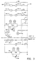
- FIG. 3 is an electrical schematic diagram of the host unit 14 and the remote unit 24.
- the host liquid line valve F is not utilized and is thus shown in the electrical schematic with a manually operable switch 87.
- switch 87 In the first embodiment of the invention switch 87 is placed in its open position, and since valve F is a normally open valve, i.e., it must be energized to close it, it will have no effect.
- switch 87 In a second embodiment of the invention, switch 87 is closed to render valve F operable. The invention will first be described without valve F.
- the host unit 14 includes a thermostat 88 having a temperature control module TCMH, a temperature sensor 90 disposed in the front compartment 12, a heat relay 1KH and a speed relay 2KH.
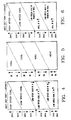
- Figure 4 is a diagram which illustrates the sequence in which the heat relay 1KH and the speed relay 2KH normally operate, with the sequence for a falling temperature descending along the left side of the diagram, and with the sequence for a rising temperature rising along the right side of the diagram.
- An upwardly pointing arrow indicates the associated relay is energized, and a downwardly pointing arrow indicates the associated relay is dropped out.
- the remote unit 24 includes a thermostat 92 having a temperature control module TCM, a temperature sensor 94 disposed in the rear compartment 20, a heat relay 1K and a speed relay 2K.
- Figure 5 is a diagram similar to that of Figure 4 except illustrating the operation of the heat and speed relays 1K and 2K, respectively, and the associated heat, cool and null modes.
- a "null" mode indicates the heating and cooling requirements are satisfied, and the temperature of the air in the associated compartment is within a predetermined small band relative to the temperature set point selected on the associated thermostat.
- thermostats 88 and 92 which thermostats are commercially available from the assignee of the present application
- the lock-out point which may be in the range of -9 to -6 degrees C (15 to 20 degrees F)
- the high speed heat mode is locked out, but low speed heat is still normally a viable mode which is initiated when the temperature is in a predetermined range below the set point.
- all host unit heat modes are locked out when the host unit receives a signal from the remote unit that the remote unit is in a cooling mode.
- This signal may be provided by heat lock out relay 3K which is connected to be energized by the same voltage which energizes the remote liquid line valve B when the temperature set point is below lock out.
- the heat lock-out relay 3K is simultaneously energized.
- Contacts 3K-1 and 3K-2 of the heat lock-out relay 3K are connected to cut out all heat modes when the remote unit 24 calls for a cooling mode and the temperature set point is below the lock-out point. While the host heat modes are locked out, the host unit is in low speed cool when it would otherwise be in a heat mode.
- a battery 96 energizes a pair of conductors 98 and 100, and the host and remote thermostats 88 and 92 are each connected between them.
- a throttle solenoid TS which controls the speed selection of the prime mover 30 is connected between the conductors 98 and 100 via normally open contacts 2KH-1 of the speed relay 2KH and normally closed contacts 1KH-3 of the host heat relay 1KH.
- the speed relay 2KH is picked up, contacts 2KH-1 close, and, if relay 1KH is dropped out, the throttle solenoid TS will be energized to advance the throttle to the high speed position.
- the speed relay 2KH drops out, contacts 2KH-1 open and the solenoid TS moves the throttle to the low speed position.
- the pilot solenoid PS is connected across conductors 98 and 100 via normally open contacts 1KH-2 of the heat relay 1KH and normally closed contacts 3K-3 of the heat lock-out relay 3K.
- the pilot solenoid PS When the heat relay 1KH is dropped out the pilot solenoid PS is deenergized and the three-way valve 32 is in the cooling position.
- the normally closed remote liquid line solenoid operated valve B is connected across conductors 98 and 100 via normally closed contacts 1K-2 of the heat relay 1K.
- contacts 1K-2 are closed, solenoid valve B is energized to open the valve and the remote unit 24 is in a cooling mode.
- solenoid valve B drops out to close the valve and terminate the remote cooling mode.
- the normally closed remote suction line solenoid valve C is connected to be energized by the same voltage which energizes the remote liquid line solenoid valve B, and the heat lock-out relay 3K is also connected to be responsive to the voltage applied to liquid line solenoid valve B, and to the location of the temperature set point relative to the predetermined heat lock-out temperature.
- the normally closed remote hot gas solenoid A is connected across conductors 98 and 100 via serially connected normally open contacts 1K-1 and 2K-1 of the heat and speed relays 1K and 2K, respectively.
- solenoid valve A When either or both of the heat and speed relays 1K and 2K are dropped out, solenoid valve A will be deenergized and closed, preventing a defrost or a heat cycle. Both the heat and speed relays 1K and 2K, respectively, must be energized before the hot gas line 82 to the remote unit 24 will be opened by the remote hot gas solenoid A.
- the normally open condenser inlet solenoid valve D is connected to be energized by the same voltage which energizes the remote hot gas solenoid A.
- the set point of the host unit 14 is below the heat lock-out temperature. This will be the normal situation, as the host unit 14 will normally be controlling the temperature of a frozen load to a predetermined temperature below -17.8 degrees C (0 degrees F).
- the heat relay 1K When the thermostat 92 of the remote unit 24 calls for a cooling mode, the heat relay 1K will drop out, contacts 1K-2 will close, the remote liquid line solenoid valve B will open to allow liquid refrigerant from the host unit 14 to enter the remote evaporator coil 74, the remote suction line valve C will energize and thus open to allow suction gas to be returned to the accumulator 54 by the host compressor 28, and the heat lock out relay 3K will pick up to lock out all heat modes, i.e., both low speed and high speed heat, in the host unit 14. In addition, valves A and D will be deenergized and thus closed and open, respectively.
- the cooling mode may be high speed cool, or low speed cool, and the remote cooling process will not be interfered with by the host unit going into a heating mode, as all heat modes have been locked out by the heat lock-out relay 3K, i.e., the pilot solenoid PS cannot be energized to switch the three-way valve 32 to the heat position.
- the host unit 14 will remain in a cooling mode all the time the remote unit 24 is in a cooling mode.
- the suction and liquid line solenoids B and C will drop out, returning the remote unit to a null mode in which both the remote liquid line 80 and the remote hot gas line 82 are closed by valves B and A, respectively.
- the host unit 14 will now be able to control to its temperature set point by cycling between low speed cool and low speed heat. The fact that the host unit cannot provide heat while the remote unit is in cool is not significant, since the host unit will normally be controlling a frozen load.
- the heat relay 1K and the speed relay 2K will both be energized as shown in Figure 5, which relays energize the normally closed remote hot gas solenoid valve A and the normally open condenser inlet solenoid valve D. Solenoid valves B and C will both be deenergized and thus closed.
- the heating mode of the remote unit will thus be highly effective whenever the host unit 14 is in a cooling mode, as all of the hot, high pressure discharge gas from the compressor 28 will be forced to flow to the remote evaporator unit 24.
- the circuit will include the host hot gas line 36, the remote hot gas line 82, the evaporator coil 74, and since valves C and D are both closed, the check valve CV2 will be open and the check valve CV1 will be closed, directing the output of the remote suction line 84 directly into the receiver tank 40.
- This arrangement not only prevents short circuiting the receiver, but it also increases the pressure in the receiver tank to force more liquid out of the receiver and increase the supply of refrigerant available for the remote heating mode.
- the heating mode of the remote unit 24 is thus highly effective, as all of the hot compressor discharge gas is directed to the remote unit 24, and more refrigerant is forced from the receiver into the active heating cycle. Defrost of the remote unit 24 will be the same as the heating mode, except the remote unit's evaporator fans will be turned off.
- the invention may be fine tuned to the needs of any specific situation by selective use of the heat lock-out relay 3K, and/or adding condenser shutters to the host unit 14.
- the system is independent of the refrigerant used, but R-502 will enhance the heating capabilities of the remote unit 24.
- the second embodiment of the invention which differs from the first embodiment by the addition of the host unit liquid line valve F, is rendered effective by closing switch 87.
- the solenoid valve F is connected such that the host liquid line 42 cannot be closed by valve F, unless refrigerant is being circulated to the remote unit 24.
- the host liquid line valve F is connected between conductors 98 and 100 via normally open contacts 1KH-1 of the host heat relay 1KH and the normally open contacts 3K-4 of the heat lock-out relay 3K.
- the host unit 14 is allowed to go into a null mode by energizing valve F, if the host unit's cooling requirements are satisfied.
- Figure 6 illustrates the modes of the host unit 14 when operating according to the second embodiment. The operation of the remote unit 24 will be the same as illustrated in the diagram of Figure 5.
- liquid line solenoids B and F would both be open, allowing their respective evaporators to provide cooling. If the host unit 14 reaches its temperature set point before the remote unit reaches its set point the heat relay 1KH picks up and the host liquid line solenoid F closes. This shuts off refrigerant to the host unit's evaporator coil 52, allowing the host unit to maintain temperature at set point without being forced to stay in a cooling mode, and without going into a heat mode. The remote unit 24 can thus continue to cool until it reaches its set point.
- the dropping out of the heat lock-out relay 3K when solenoid valve B drops causes the liquid line solenoid F to re-open at the same instant that the remote liquid line solenoid B closes.
- the host unit would then maintain set point by cycling between low speed cool and low speed heat.
- liquid line solenoid valve B would close while liquid line solenoid valve F would remain open.
- the liquid line solenoid valve F would remain open, and the host unit will then maintain its set point by cycling between low speed cool and low speed heat.
- the remote unit 24 should require cooling while the host unit 14 is in a heat mode, the liquid line solenoid valves F and B would close and open, respectively, the heat lock-out relay 3K would pick up and cause the pilot solenoid PS to drop out, returning the three-way valve 32 of the host unit 14 to the cooling position, until the cooling needs of the remote unit are satisfied.
- the system would always operate to circulate refrigerant through the compressor 28, with the heating and cooling needs of the remote unit both taking precedence over the heating needs of the host unit. Also, the fact that the host unit can go into null to maintain setpoint, allows the cooling needs of the remote unit to be better served during this period.
Landscapes
- Engineering & Computer Science (AREA)
- Physics & Mathematics (AREA)
- Mechanical Engineering (AREA)
- Thermal Sciences (AREA)
- General Engineering & Computer Science (AREA)
- Chemical & Material Sciences (AREA)
- Combustion & Propulsion (AREA)
- Devices That Are Associated With Refrigeration Equipment (AREA)
Claims (6)
- Verfahren zum Steuern der Temperatur eines in Abteile aufgeteilten Transportkühlsystems, wobei die Temperatur in einem ersten Abteil (12) eines Trailers auf einen ersten Einstellwert mittels einer Hauptkühleinheit (14), die einen Verdichter (28), einen Kondensator (38), einen Sammelbehälter (40) und einen Verdampfer (52) aufweist, und die Temperatur eines zweiten Trailerabteils (20) auf einen zweiten Einstellwert mittels eines entfernt angeordneten Verdampfers (24), der wahlweise mit der Hauptkühleinheit verbindbare Flüssigkeits-, Heißgas- und Saugleitungen (80,82,84) aufweist, gesteuert wird, dadurch gekennzeichnet, daß verhindert wird, daß die Haupteinheit in einen Heizbetrieb geht, wenn die Haupteinheit Wärme benötigt zum Aufrechterhalten des ersten Einstellwertes als Reaktion auf die entfernte Einheit, die Kühlung benötigt zum Aufrechterhalten des zweiten Einstellwertes, während die Haupteinheit auf einen ersten Einstellwert steuert, der unterhalb eines vorbestimmten Wertes ist, daß ein Heizbetrieb der Haupteinheit zu jeder Zeit, wenn die entfernte Einheit Kühlung benötigt, beendet wird und daß das gesamte Abgas von den Kompressoren zum entfernten Verdampfer gelenkt wird, wenn der entfernte Verdampfer Wärme benötigt zum Aufrechterhalten des zweiten Einstellwertes, während sich die Haupteinheit nicht in einem Heizbetrieb befindet.
- Verfahren nach Anspruch 1, wobei das Lenken des Abgases vom Kompressor das Einrichten der Heißgasleitung vom Kompressor zum entfernten Verdampfer, das Verhindern, daß Heißgas vom Kompressor in den Kondensator gelangt, und das Verbinden der Ansaugleitung des entfernten Verdampfers direkt mit dem Sammelbehälter umfaßt.
- Verfahren nach Anspruch 1, bei dem die Temperatur des ersten Abteils durch zyklisches Betreiben zwischen Kühl- und Nullbetriebsarten der Haupteinheit gesteuert wird, während sich der entfernte Verdampfer in einem Kühlbetrieb befindet, und wobei das Verfahren das Bereitstellen von ersten und zweiten Flüssigkeitsleitungs-Steuerorganen zum selektiven Schließen der Flüssigkeitsleitungen der Haupteinheit bzw. des entfernten Verdampfers, und das Blockieren der Steuerorgane, so daß das erste Flüssigkeitsleitungs-Steuerorgan die Hauptflüssigkeitsleitung nur dann schließen kann, während sich der entfernte Verdampfer in einem Kühlbetrieb befindet, umfaßt.
- Verfahren nach Anspruch 3, bei dem die Haupteinheit daran gehindert ist, in den Heizbetrieb zu gehen, wenn sich die entfernte Einheit in einem Kühlbetrieb befindet.
- In Abteile aufgeteiltes Transportkühlsystem mit einem Trailer (10), der aufweist:
ein erstes Abteil (12),
eine Haupteinheit (14) zum Steuern der Lufttemperatur des ersten Abteils mittels Heiz-, Kühl- und Nullbetriebsarten, wobei die Haupteinheit (14) einen geschlossenen Fluidkreislauf aufweist, welcher einen Verdichter (28), einen Kondensator (38), einen Sammelbehälter (40), einen Verdampfer (52) sowie Flüssigkeits-, Heißgas- und Saugleitungen (42,36,60) umfaßt,
ein zweites Abteil (20) im Trailer,
einen entfernt angeordneten Verdampfer (24) zum Steuern der Lufttemperatur des zweiten Abteils mittels Heiz-, Kühl- und Nullbetriebsarten, wobei der entfernt angeordnete Verdampfer mit den jeweiligen Flüssigkeits-, Heißgas- und Saugleitungen der Haupteinheit verbundene Flüssigkeits-, Heißgas- und Saugleitungen (80,82,84) enthält,
eine erste Einrichtung (D) für selektives Bewirken und Blockieren einer Fluidströmung von der Hochdruckseite des Kompressors (28) zum Kondensator (38), wenn sich die Haupteinheit (14) in einem Kühlbetrieb befindet,
zweite, dritte und vierte Einrichtungen (B,A,C) für jeweiliges und selektives Bewirken und Blockieren einer Fluidströmung zwischen den entfernten Flüssigkeits-, Heißgas- und Ansaugleitungen und der Haupteinheit (14),
ein Einweg-Bypassmittel (CV2), das die Ansaugleitung (84) des entfernten Verdampfers (24) und den Sammelbehälter (40) der Haupteinheit (14) verbindet,
und Steuermittel zum Auswählen der fluidblockierenden Stellungen des ersten (D), zweiten (B) und vierten (C) Mittels, wenn das dritte Mittel (A) die Heißgasleitung (36) der Haupteinheit (14) mit dem entfernten Verdampfer (24) verbindet,
und Mittel zum Verhindern, daß die Haupteinheit (14) einen Heizbetrieb beginnt, wenn das zweite Mittel (B) einen entfernten Kühlbetrieb beginnt und die Haupteinheit (14) auf eine Temperatur unterhalb des vorbestimmten Wertes steuert. - Transportkühlsystem nach Anspruch 5, das ein fünftes Mittel (F) in der Flüssigkeitsleitung der Haupteinheit (14) für selektives Bewirken und Blockieren einer Fluidströmung vom Sammelbehälter (40) zum Verdampfer (52) enthält, und bei dem das Steuermittel ein Mittel für zyklisches Betreiben des fünften Mittels (F) zum Steuern der Lufttemperatur im ersten Abteil (12) durch Kühl- und Nullbetriebsarten, wenn das zweite Mittel (B) einen Kühlbetrieb im entfernten Verdampfer (24) bereitstellt, und ein Mittel (3K-4) zum Verhindern, daß das fünfte Mittel (F) die Hauptflüssigkeitsleitung (42) blockiert, während der entfernte Verdampfer sich in einem Nullbetrieb befindet, enthält.
Applications Claiming Priority (2)
| Application Number | Priority Date | Filing Date | Title |
|---|---|---|---|
| US915827 | 1986-10-06 | ||
| US06/915,827 US4711095A (en) | 1986-10-06 | 1986-10-06 | Compartmentalized transport refrigeration system |
Publications (3)
| Publication Number | Publication Date |
|---|---|
| EP0265123A2 EP0265123A2 (de) | 1988-04-27 |
| EP0265123A3 EP0265123A3 (en) | 1989-07-19 |
| EP0265123B1 true EP0265123B1 (de) | 1992-01-08 |
Family
ID=25436312
Family Applications (1)
| Application Number | Title | Priority Date | Filing Date |
|---|---|---|---|
| EP87308904A Expired - Lifetime EP0265123B1 (de) | 1986-10-06 | 1987-10-02 | Kühlsystem für Mehrkammertransporte |
Country Status (4)
| Country | Link |
|---|---|
| US (2) | US4711095A (de) |
| EP (1) | EP0265123B1 (de) |
| JP (1) | JPS63213777A (de) |
| DE (1) | DE3775881D1 (de) |
Cited By (2)
| Publication number | Priority date | Publication date | Assignee | Title |
|---|---|---|---|---|
| DE4307931B4 (de) * | 1992-03-12 | 2005-04-07 | Thermo King Corp., Minneapolis | Verfahren zum Betrieb eines Mehrkammer-Transportkühlsystems |
| CN104508405A (zh) * | 2012-07-31 | 2015-04-08 | 大金工业株式会社 | 集装箱用制冷装置 |
Families Citing this family (32)
| Publication number | Priority date | Publication date | Assignee | Title |
|---|---|---|---|---|
| US4850197A (en) * | 1988-10-21 | 1989-07-25 | Thermo King Corporation | Method and apparatus for operating a refrigeration system |
| US4896512A (en) * | 1989-01-25 | 1990-01-30 | Thermo King Corporation | Compartmentalized transport refrigeration system |
| US4903495A (en) * | 1989-02-15 | 1990-02-27 | Thermo King Corp. | Transport refrigeration system with secondary condenser and maximum operating pressure expansion valve |
| US4912940A (en) * | 1989-05-15 | 1990-04-03 | Thermo King Corporation | Refrigerant evaporator suitable for remote mounting |
| US4932219A (en) * | 1989-10-26 | 1990-06-12 | Thermo King Corporation | Transport refrigeration system with selective receiver tank pressurization |
| US5065587A (en) * | 1991-01-28 | 1991-11-19 | Thermo King Corporation | Compartmentalized transport refrigeration system |
| US5107686A (en) * | 1991-01-28 | 1992-04-28 | Thermo King Corporation | Compartmentalized transport refrigeration system |
| US5129235A (en) * | 1991-08-26 | 1992-07-14 | Thermo King Corporation | Compartmentalized transport refrigeration system |
| US5172559A (en) * | 1991-10-31 | 1992-12-22 | Thermo King Corporation | Compartmentalized transport refrigeration system having means for enhancing the capacity of a heating cycle |
| US20020129613A1 (en) * | 2000-10-10 | 2002-09-19 | Thermo King Corporation | Cryogenic refrigeration unit suited for delivery vehicles |
| US6560978B2 (en) | 2000-12-29 | 2003-05-13 | Thermo King Corporation | Transport temperature control system having an increased heating capacity and a method of providing the same |
| US6751966B2 (en) * | 2001-05-25 | 2004-06-22 | Thermo King Corporation | Hybrid temperature control system |
| DE10224724A1 (de) * | 2001-06-04 | 2003-01-30 | Thermo King Corp | Steuerverfahren für ein CRYO-Kühlsystem mit Eigenantrieb |
| US6631621B2 (en) * | 2001-07-03 | 2003-10-14 | Thermo King Corporation | Cryogenic temperature control apparatus and method |
| US6698212B2 (en) * | 2001-07-03 | 2004-03-02 | Thermo King Corporation | Cryogenic temperature control apparatus and method |
| US6694765B1 (en) * | 2002-07-30 | 2004-02-24 | Thermo King Corporation | Method and apparatus for moving air through a heat exchanger |
| US6895764B2 (en) * | 2003-05-02 | 2005-05-24 | Thermo King Corporation | Environmentally friendly method and apparatus for cooling a temperature controlled space |
| US6910341B2 (en) * | 2003-09-26 | 2005-06-28 | Thermo King Corporation | Temperature control apparatus and method of operating the same |
| US7451614B2 (en) * | 2004-04-01 | 2008-11-18 | Perlick Corporation | Refrigeration system and components thereof |
| TW200617280A (en) * | 2004-11-29 | 2006-06-01 | wen-xiu Ou | Power generating method and engine utilizing the natural heat without fuel |
| US7089740B1 (en) * | 2005-02-22 | 2006-08-15 | Yi-Lung Phyllis Hsu | Method of generating power from naturally occurring heat without fuels and motors using the same |
| US8109327B2 (en) * | 2006-10-23 | 2012-02-07 | Thermo King Corporation | Temperature control system having heat exchange modules with indirect expansion cooling and in-tube electric heating |
| BRPI0722085A2 (pt) * | 2007-01-08 | 2014-04-01 | Carrier Corp | Sistema de transporte refrigerado e método para operar o mesmo |
| US20100107661A1 (en) * | 2007-02-02 | 2010-05-06 | Awwad Nader S | Method for operating transport refrigeration unit with remote evaporator |
| US20100050665A1 (en) * | 2007-08-13 | 2010-03-04 | B/E Aerospace, Inc. | Method and apparatus for maintaining a uniform temperature in a refrigeration system |
| KR20090041130A (ko) * | 2007-10-23 | 2009-04-28 | 현대자동차주식회사 | 차량용 난방 기동제어 방법 |
| WO2012166144A1 (en) * | 2011-06-02 | 2012-12-06 | Carrier Corporation | System and method for cooling a compartmentalized refrigeration enclosure |
| US8677779B2 (en) * | 2011-10-31 | 2014-03-25 | Ford Global Technologies, Llc | Air conditioner with series/parallel secondary evaporator and single expansion valve |
| CN104884305B (zh) * | 2012-12-27 | 2018-10-16 | 冷王公司 | 运输制冷系统的特定地理控制 |
| EP3014197B1 (de) | 2013-06-26 | 2022-01-12 | Carrier Corporation | Mehrkammern-transportkühlsystem mit verdampferisolierventil |
| CN106004635A (zh) * | 2016-06-27 | 2016-10-12 | 吴健 | 一种果蔬运输车 |
| SE541964C2 (en) * | 2016-07-12 | 2020-01-14 | Es Energy Save Holding Ab | Heat pump apparatus module |
Family Cites Families (8)
| Publication number | Priority date | Publication date | Assignee | Title |
|---|---|---|---|---|
| US2237249A (en) * | 1938-09-30 | 1941-04-01 | Honeywell Regulator Co | Refrigeration control system |
| US2403818A (en) * | 1943-08-26 | 1946-07-09 | Honeywell Regulator Co | Refrigeration system |
| US2960840A (en) * | 1956-02-27 | 1960-11-22 | Fred J Hosken | Method and apparatus for defrosting a refrigeration system |
| US3219102A (en) * | 1961-12-22 | 1965-11-23 | Thermo King Corp | Method and apparatus for deriving heat from refrigerant evaporator |
| GB988874A (en) * | 1962-01-09 | 1965-04-14 | Maurice Wishard Brainard | Heating and cooling system |
| US3664150A (en) * | 1970-12-30 | 1972-05-23 | Velt C Patterson | Hot gas refrigeration defrosting system |
| US4325224A (en) * | 1980-04-29 | 1982-04-20 | Thermo King Corp. | Method and apparatus for transport refrigeration system control |
| US4419866A (en) * | 1982-06-09 | 1983-12-13 | Thermo King Corporation | Transport refrigeration system control |
-
1986
- 1986-10-06 US US06/915,827 patent/US4711095A/en not_active Expired - Fee Related
-
1987
- 1987-04-09 US US07/036,539 patent/US4706468A/en not_active Expired - Fee Related
- 1987-10-02 DE DE8787308904T patent/DE3775881D1/de not_active Expired - Lifetime
- 1987-10-02 EP EP87308904A patent/EP0265123B1/de not_active Expired - Lifetime
- 1987-10-05 JP JP62250053A patent/JPS63213777A/ja active Pending
Cited By (3)
| Publication number | Priority date | Publication date | Assignee | Title |
|---|---|---|---|---|
| DE4307931B4 (de) * | 1992-03-12 | 2005-04-07 | Thermo King Corp., Minneapolis | Verfahren zum Betrieb eines Mehrkammer-Transportkühlsystems |
| CN104508405A (zh) * | 2012-07-31 | 2015-04-08 | 大金工业株式会社 | 集装箱用制冷装置 |
| CN104508405B (zh) * | 2012-07-31 | 2016-06-08 | 大金工业株式会社 | 集装箱用制冷装置 |
Also Published As
| Publication number | Publication date |
|---|---|
| EP0265123A3 (en) | 1989-07-19 |
| US4706468A (en) | 1987-11-17 |
| JPS63213777A (ja) | 1988-09-06 |
| US4711095A (en) | 1987-12-08 |
| DE3775881D1 (de) | 1992-02-20 |
| EP0265123A2 (de) | 1988-04-27 |
Similar Documents
| Publication | Publication Date | Title |
|---|---|---|
| US4711095A (en) | Compartmentalized transport refrigeration system | |
| US4685306A (en) | Compartmentalized transport refrigeration system | |
| US4712383A (en) | Compartmentalized transport refrigeration system | |
| US5065587A (en) | Compartmentalized transport refrigeration system | |
| US5596878A (en) | Methods and apparatus for operating a refrigeration unit | |
| US4977752A (en) | Transport refrigeration including methods and apparatus for optmizing same | |
| EP0392673B1 (de) | Transportkühlsystem mit Mitteln zum Vergrössern der Kapazität eines Heizzyklus | |
| US6708510B2 (en) | Advanced refrigeration system | |
| US5056324A (en) | Transport refrigeration system having means for enhancing the capacity of a heating cycle | |
| US20030024256A1 (en) | Automatic switching refrigeration system | |
| US5172559A (en) | Compartmentalized transport refrigeration system having means for enhancing the capacity of a heating cycle | |
| EP2420788A2 (de) | Temperatursteuerung mit Zonenpriorität in einem Transportkühlsystem mit mehreren Zonen | |
| US4920756A (en) | Transport refrigeration system with dehumidifier mode | |
| KR19980042426A (ko) | 자동차용 열펌프식 공조 시스템 | |
| JPH06174315A (ja) | 可変速度圧縮器を備えた複数温度形蒸発冷凍装置 | |
| US5193353A (en) | High capacity hot gas heating system for transport refrigeration system | |
| GB2205977A (en) | Method of operating a transport refrigeration system having a six cylinder compressor | |
| US5415006A (en) | Transport refrigeration unit having means for increasing the amount of refrigerant charge available | |
| US4327558A (en) | Unloadable transport refrigeration unit control | |
| US5107686A (en) | Compartmentalized transport refrigeration system | |
| JPS6155017B2 (de) | ||
| US4896512A (en) | Compartmentalized transport refrigeration system | |
| JP2003035462A (ja) | 冷蔵庫 | |
| JPS6225660Y2 (de) | ||
| JPH10315753A (ja) | 冷凍冷房装置 |
Legal Events
| Date | Code | Title | Description |
|---|---|---|---|
| PUAI | Public reference made under article 153(3) epc to a published international application that has entered the european phase |
Free format text: ORIGINAL CODE: 0009012 |
|
| AK | Designated contracting states |
Kind code of ref document: A2 Designated state(s): DE FR GB IT |
|
| PUAL | Search report despatched |
Free format text: ORIGINAL CODE: 0009013 |
|
| AK | Designated contracting states |
Kind code of ref document: A3 Designated state(s): DE FR GB IT |
|
| 17P | Request for examination filed |
Effective date: 19890904 |
|
| 17Q | First examination report despatched |
Effective date: 19900510 |
|
| GRAA | (expected) grant |
Free format text: ORIGINAL CODE: 0009210 |
|
| AK | Designated contracting states |
Kind code of ref document: B1 Designated state(s): DE FR GB IT |
|
| ET | Fr: translation filed | ||
| REF | Corresponds to: |
Ref document number: 3775881 Country of ref document: DE Date of ref document: 19920220 |
|
| ITF | It: translation for a ep patent filed | ||
| PLBE | No opposition filed within time limit |
Free format text: ORIGINAL CODE: 0009261 |
|
| STAA | Information on the status of an ep patent application or granted ep patent |
Free format text: STATUS: NO OPPOSITION FILED WITHIN TIME LIMIT |
|
| 26N | No opposition filed | ||
| PGFP | Annual fee paid to national office [announced via postgrant information from national office to epo] |
Ref country code: FR Payment date: 19930914 Year of fee payment: 7 |
|
| PGFP | Annual fee paid to national office [announced via postgrant information from national office to epo] |
Ref country code: GB Payment date: 19930922 Year of fee payment: 7 |
|
| PGFP | Annual fee paid to national office [announced via postgrant information from national office to epo] |
Ref country code: DE Payment date: 19931231 Year of fee payment: 7 |
|
| PG25 | Lapsed in a contracting state [announced via postgrant information from national office to epo] |
Ref country code: GB Effective date: 19941002 |
|
| GBPC | Gb: european patent ceased through non-payment of renewal fee |
Effective date: 19941002 |
|
| PG25 | Lapsed in a contracting state [announced via postgrant information from national office to epo] |
Ref country code: FR Effective date: 19950630 |
|
| PG25 | Lapsed in a contracting state [announced via postgrant information from national office to epo] |
Ref country code: DE Effective date: 19950701 |
|
| REG | Reference to a national code |
Ref country code: FR Ref legal event code: ST |
|
| PG25 | Lapsed in a contracting state [announced via postgrant information from national office to epo] |
Ref country code: IT Free format text: LAPSE BECAUSE OF NON-PAYMENT OF DUE FEES;WARNING: LAPSES OF ITALIAN PATENTS WITH EFFECTIVE DATE BEFORE 2007 MAY HAVE OCCURRED AT ANY TIME BEFORE 2007. THE CORRECT EFFECTIVE DATE MAY BE DIFFERENT FROM THE ONE RECORDED. Effective date: 20051002 |