EP0265146A2 - Lecteur de données portable équipé d'une imprimante modulaire amovible - Google Patents
Lecteur de données portable équipé d'une imprimante modulaire amovible Download PDFInfo
- Publication number
- EP0265146A2 EP0265146A2 EP87309027A EP87309027A EP0265146A2 EP 0265146 A2 EP0265146 A2 EP 0265146A2 EP 87309027 A EP87309027 A EP 87309027A EP 87309027 A EP87309027 A EP 87309027A EP 0265146 A2 EP0265146 A2 EP 0265146A2
- Authority
- EP
- European Patent Office
- Prior art keywords
- printer
- module
- printer module
- cartridge
- printer cartridge
- Prior art date
- Legal status (The legal status is an assumption and is not a legal conclusion. Google has not performed a legal analysis and makes no representation as to the accuracy of the status listed.)
- Withdrawn
Links
Images



Classifications
-
- G—PHYSICS
- G06—COMPUTING OR CALCULATING; COUNTING
- G06K—GRAPHICAL DATA READING; PRESENTATION OF DATA; RECORD CARRIERS; HANDLING RECORD CARRIERS
- G06K7/00—Methods or arrangements for sensing record carriers, e.g. for reading patterns
- G06K7/10—Methods or arrangements for sensing record carriers, e.g. for reading patterns by electromagnetic radiation, e.g. optical sensing; by corpuscular radiation
-
- G—PHYSICS
- G06—COMPUTING OR CALCULATING; COUNTING
- G06K—GRAPHICAL DATA READING; PRESENTATION OF DATA; RECORD CARRIERS; HANDLING RECORD CARRIERS
- G06K17/00—Methods or arrangements for effecting co-operative working between equipments covered by two or more of main groups G06K1/00 - G06K15/00, e.g. automatic card files incorporating conveying and reading operations
-
- G—PHYSICS
- G06—COMPUTING OR CALCULATING; COUNTING
- G06K—GRAPHICAL DATA READING; PRESENTATION OF DATA; RECORD CARRIERS; HANDLING RECORD CARRIERS
- G06K7/00—Methods or arrangements for sensing record carriers, e.g. for reading patterns
- G06K7/10—Methods or arrangements for sensing record carriers, e.g. for reading patterns by electromagnetic radiation, e.g. optical sensing; by corpuscular radiation
- G06K2007/10524—Hand-held scanners
Definitions
- the present invention relates generally to an integrated, self-contained handheld data scanner apparatus, and particularly to a removable printer module for use in conjunction with such apparatus.
- Bar code symbols consisting of a strip of alternating dark bars and light spaces, and bar code scanners for reading bar codes, have become widely used in many industries for a variety of tasks. For example, one large overnight package delivery service has recently advertised the use of bar codes and a handheld bar code scanner for purposes of computerized tracking of the location of packages from their time of pickup until their delivery.
- the typical bar code reading wand is a pen-like device having a light source and photodetector located in its tip.
- the tip of the wand is either rubbed in contact with or waved in close proximity to the bar code symbol.
- the photodetector senses changes in the reflectance of the symbol as the tip crosses the dark bars and light spaces of the symbols.
- the bar code symbol to be scanned must be located at a fixed focal distance.
- U.S. Patents Nos. 4,460,120, 4,409,470, 4,387,297, 4,360,798 and 4,251,798 See, for example, U.S. Patents Nos. 4,460,120, 4,409,470, 4,387,297, 4,360,798 and 4,251,798.
- the portable scanning head includes a resilient contact pad which contacts and conforms to the surface on which the bar code symbol to be scanned is imprinted.
- the present invention describes a removable printer module and the details of mechanical and electrical interconnection to a portable data scanner so that a lightweight portable unit including a printer is provided.
- the removable printer preferably includes a reversible printing cartridge arrangement so that the overall unit may be readily adapted for easy usage by both lefthanded and righthanded operators.
- Fig. 1 illustrates an overall unit 1 comprising an integrated self-contained laser based bar code scanner apparatus 90 interconnected to a printer module 10 constructed according to the present invention.
- the preferred self-contained apparatus 90 shown in Fig. 1 is rugged, compact, lightweight and intended for long periods of uninterrupted handheld use for noncontact barcode scanning over a range of focal distances in a variety of environments. These characteristics are desirable because it is expected that that apparatus will be carried by the operator to various locations. Further, the apparatus 90 eliminates interconnecting cables and belt mounted components. Consequently, the repetitive scanning of bar codes with the present apparatus can be a one-handed operation allowing the other hand free for other functions.
- the printer module 10 is designed consistently with the objectives of the apparatus 90 so that unit 1 is also portable and integrated.
- the self-contained apparatus 90 includes a number of modules: a scanner module 100, a frame module 200, a data module 300, including one or more data processing components, and a removable, rechargable battery module 400 combined to achieve the beneficial result of true portability in a single integrated unit without power or data transfer cabling to separate power packs or data processing apparatus.
- printer module 10 The details of printer module 10 are illustrated in Figs. 2-8.
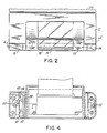
- Fig. 2 which is a front view of printer module 10, the exterior components of printer module 10 are shown.
- the printer module 10 is mechanically and electrically connected to base 210 of frame module 200 of the portable data scanner apparatus 90. Only a portion of the base 210 is shown in Fig. 2.
- Printer module 10 is a compact unit having an outer housing 12, a printer cartridge 13, two end caps 14 and 15, a clear facing 18 allowing the operator to see when paper needs to be added, and a serrated edge 19 for cutting off printer paper.
- the printer cartridge 13 fits into the outer housing 12 and the two end caps 14 and 15 along with a pair of pivot clamps 30 and 31 (shown in Fig. 5) lock the cartridge 13 in place in the housing 12 as will be further discussed below.
- a pair of pivot clamps 30 and 31 shown in Fig. 5
- the cartridge 13 can be readily removed.
- Cartridge 13 can be removed, rotated 180°, and reinserted in the housing 12 so that the paper of the printer module will exist on the opposite side of the printer module 10. This reversibility which will be discussed in greater detail below gives printer module 10 great flexibility for either righthanded or lefthanded operation.
- Fig. 3 is a sectional view which illustrates various internal details of printer module 10 relevant to the interconnection of apparatus 90 and printer module 10, and the reversibility of the printer cartridge 13.
- the printer cartridge 13 includes a printer mechanism 16, a paper roll mandrel 17 which will typically have a roll of pape. 27 mounted on it, and a printed circuit board 20, all of which are housed within a symmetrical printer cartridge housing 21.
- Printer cartridge 13 also includes a pair of electrical contact surfaces 38 and 39 symmetrically mounted on the opposite ends of the housing 21. Because the printer cartridge housing 21 is symmetrical, it and the printing components housed therein can be removed, rotated 180°, and placed back into the outer housing 12 of printer module 10. The details of the electrical connection of control signals and power to printer cartridge 13 in a manner which is consistent with the above reversibility are discussed below.
- the electrical contact surface 38 is located adjacent an electrical connector 41 with a spring biased contact pad 42.
- the contact pad 42 includes a plurality of contact strips or fingers which make contact with corresponding strips or fingers of the contact surface 38 (or surface 39 if cartridge 13 is reversed).
- the spring biased contact 42 is shown in a recessed position so that electrical contact is not made to the contact surface 38 of printer cartridge 13.
- the pivot clamp 30 is in a closed position and clamp 31 is in an open position. When both pivot clamps are open, the printer cartridge 13 can be readily removed. When both pivot clamps are closed, as shown in Fig. 5, the printer cartridge 33 is locked in place.
- the pivot clamps 30 and 31 include slots 34 and 35 respectively which facilitate rotation of the pivot clamps.
- the operator may use a United States 10 cents coin to provide leverage to lock and unlock the pivot clamps.
- detents 36 and 37 hold the clamps 30 and 31 locked in their closed position.
- the printed circuit board 43 extends upwardly from its end having the electrical connector 41 to make electrical connection with an input output electrical connector 46 which is preferably an RS 232 connector for the input or output of data to or from the unit 1 including the printer module 10.
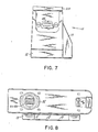
- Fig. 7 illustrates the external appearance of this connector 46, as well as, a side view of the printer module 10 attached to the base 210 of the apparatus 90.
- Printed circuit board 43 also includes an electrical connector 36 which is electrically connected to an electrical connector in apparatus 90. To summarize, data, control signals such as for controlling the operation of printer mechanism 16 and power from apparatus 90 are electrically connected through the electrical connector 36 to printed circuit board 43. The board 43 connects these data, control and power signals to the connector 46 so that data can be output from the overall unit 1 provided these signals are for external use. If information is to be printed, then printed circuit board 43 connects the signals through connector 41, spring biased contact pad 42 and surface contact 38 to the printed circuit board 20 in the printer cartridge 13. Printed circuit board 43 contains control circuitry for controlling the printer mechanism 16 and printer circuit board 20 connects control signals to the printer mechanism 16. Printer mechanism 16 causes the information to be printed on the paper of paper roll 27.
- the preferred mechanical connection is an interlocking one made with a bayonet configuration as illustrated in Figs. 3 and 8.
- Other interlocking means may be used.
- the interlocking means includes a collar 32 which is preferably a molded part of outer housing 22.
- Collar 32 has a bayonet configuration as shown in Fig. 8 which allows the printer module 10 to be mounted to an interface connector opening 213 in base 210 of the portable data scanner apparatus 90. Locking is achieved via a bayonet lock ring 217 which is also part of the base 210.
- printer module 10 Mechanical interconnection is summarized as follows.
- the collar 32 of printer module 10 is inserted into opening 213 with the printer module 10 positioned orthagonally to the base 210 of the portable data scanner apparatus 90.
- the printer module 10 is rotated so that it is aligned with the base 210.
- printer module 10 can be readily rotated between the orthagonal and aligned positions. Such rotation allows ready access to the base of the apparatus 90, and allows access to a locking screw 214 which locks battery module 400 in place.
- a latch 35 Once the printer module 10 is aligned with base 210, it is latched in place by a latch 35 which snaps into a molded recess 215 in the base 210. Latch 35 pushes to lock-on and pulls to unlock-off (off position is shown in dashed lines in Fig. 3).
- printer module 10 Electrical connection between printer module 10 and data scanner apparatus 90 is made as follows.
- An electrical connector 36 seen from the top in Fig. 8 and from the side in Fig. 3 is manually set to a detent position in which it is properly aligned with the opposing electrical connector in the apparatus 90 when the printer module 10 is orthagonal to base 210 and collar 32 is aligned for insertion into opening 213.
- Proper electrical interconnection is automatically made as the printer module 10 is mated through the bayonet opening and pushed up into the base of apparatus 90.
- This arrangement is particularly beneficial as it requires the operator only to perform the simple task of placing connector 36 in its detent position, to achieve proper alignment, and thereby eliminates a potential source of damage to the connector 36 and the electrical connector in the apparatus 90.
- Fig. 6 is a side view of the printer module 10.
- the printer module 10 preferably includes a slide switch 51 for turning the printer on and off.
- the slide switch 51 is electrically connected to the printed circuit board 43 located inside printer housing 12.
- Printer module 10 also preferably includes a paper advance switch 52 which is also electrically connected to the printed circuit board 43.
- the printer module 10 has a substantially flat base 53 which can serve as the base for the entire unit 1 when the operator wishes to put unit 1 down.
Landscapes
- Physics & Mathematics (AREA)
- Engineering & Computer Science (AREA)
- General Physics & Mathematics (AREA)
- Theoretical Computer Science (AREA)
- General Health & Medical Sciences (AREA)
- Electromagnetism (AREA)
- Health & Medical Sciences (AREA)
- Toxicology (AREA)
- Artificial Intelligence (AREA)
- Computer Vision & Pattern Recognition (AREA)
- Printers Characterized By Their Purpose (AREA)
- Facsimile Scanning Arrangements (AREA)
- Facsimiles In General (AREA)
Applications Claiming Priority (2)
| Application Number | Priority Date | Filing Date | Title |
|---|---|---|---|
| US918508 | 1986-10-14 | ||
| US06/918,508 US4727245A (en) | 1986-10-14 | 1986-10-14 | Portable data scanner with removable modular printer |
Publications (2)
| Publication Number | Publication Date |
|---|---|
| EP0265146A2 true EP0265146A2 (fr) | 1988-04-27 |
| EP0265146A3 EP0265146A3 (fr) | 1989-10-25 |
Family
ID=25440487
Family Applications (1)
| Application Number | Title | Priority Date | Filing Date |
|---|---|---|---|
| EP87309027A Withdrawn EP0265146A3 (fr) | 1986-10-14 | 1987-10-13 | Lecteur de données portable équipé d'une imprimante modulaire amovible |
Country Status (11)
| Country | Link |
|---|---|
| US (1) | US4727245A (fr) |
| EP (1) | EP0265146A3 (fr) |
| JP (1) | JPH01501184A (fr) |
| KR (1) | KR880701926A (fr) |
| AU (2) | AU607447B2 (fr) |
| BR (1) | BR8707499A (fr) |
| CA (1) | CA1298406C (fr) |
| DK (1) | DK324388D0 (fr) |
| IE (1) | IE872730L (fr) |
| MX (1) | MX160669A (fr) |
| WO (1) | WO1988002893A1 (fr) |
Families Citing this family (71)
| Publication number | Priority date | Publication date | Assignee | Title |
|---|---|---|---|---|
| US5313053A (en) * | 1990-01-18 | 1994-05-17 | Norand Corporation | Laser scanner module having integral interfacing with hand-held data capture terminal |
| US20070007353A1 (en) * | 1986-08-08 | 2007-01-11 | Danielson Arvin D | Laser scanner module having integral interface with hand-held data capture terminal, proximity and label sensing, and enhanced sensitivity and power efficiency |
| US5218187A (en) * | 1990-01-18 | 1993-06-08 | Norand Corporation | Hand-held data capture system with interchangeable modules |
| US5202817A (en) * | 1989-06-07 | 1993-04-13 | Norand Corporation | Hand-held data capture system with interchangeable modules |
| US6621942B1 (en) * | 1989-09-29 | 2003-09-16 | Intermec Ip Corp. | Data capture apparatus with handwritten data receiving component |
| US5949056A (en) * | 1986-09-10 | 1999-09-07 | Norand Corporation | Method and apparatus for optically reading an information pattern |
| US4890230A (en) * | 1986-12-19 | 1989-12-26 | Electric Industry Co., Ltd. | Electronic dictionary |
| GB2206432B (en) * | 1987-05-20 | 1991-07-24 | Furuno Electric Co | Bar code printing and/or reading apparatus |
| US5023438A (en) * | 1988-11-26 | 1991-06-11 | Nitto Kohki Co., Ltd. | Portable data input apparatus with different display modes |
| US5888087A (en) * | 1989-01-31 | 1999-03-30 | Norand Corporation | One-handed dock for a portable data collection terminal |
| US5331580A (en) * | 1989-01-31 | 1994-07-19 | Norand Corporation | Data capture system with communicating and recharging docking apparatus, and modular printer and hand-held data terminal means cooperable therewith |
| CA1329263C (fr) * | 1989-03-01 | 1994-05-03 | Mark Krichever | Lecteur de codes a barres |
| CA1334218C (fr) * | 1989-03-01 | 1995-01-31 | Jerome Swartz | Lecteur laser de codes a barres portatif |
| US5278551A (en) * | 1989-03-20 | 1994-01-11 | Nitto Kohki Co., Ltd. | Meter reading system |
| US6714983B1 (en) | 1989-04-14 | 2004-03-30 | Broadcom Corporation | Modular, portable data processing terminal for use in a communication network |
| US5515303A (en) * | 1989-04-14 | 1996-05-07 | Norand Corporation | Hand-held computerized data collection terminal with rechargeable battery pack sensor and battery power conservation |
| US7388742B2 (en) * | 1989-04-14 | 2008-06-17 | Broadcom Corporation | Portable computerized data communication device |
| US5331136A (en) * | 1990-01-18 | 1994-07-19 | Norand Corporation | Hand-held data capture system with interchangeable modules |
| US7537167B1 (en) * | 1993-08-31 | 2009-05-26 | Broadcom Corporation | Modular, portable data processing terminal for use in a radio frequency communication network |
| US5418684A (en) * | 1989-06-07 | 1995-05-23 | Norand Corporation | Hand-held data capture system with interchangeable modules |
| US5530619A (en) * | 1989-06-07 | 1996-06-25 | Norand Corporation | Hand-held data capture system with interchangeable modules and side-mounted function key |
| US5189291A (en) * | 1989-05-01 | 1993-02-23 | Symbol Technologies, Inc. | Bar code reader operable as remote scanner or with fixed terminal |
| ES2210223T3 (es) * | 1989-06-07 | 2004-07-01 | Broadcom Corporation | Sistema portatil de captura de datos con modulos intercambiables. |
| US6244512B1 (en) | 1989-06-08 | 2001-06-12 | Intermec Ip Corp. | Hand-held data capture system with interchangeable modules |
| US5347115A (en) * | 1990-01-12 | 1994-09-13 | Norand Corporation | Portable modular work station including printer and portable data collection terminal |
| US6431451B1 (en) * | 1991-02-25 | 2002-08-13 | Intermec Ip Corp. | Hand-held data capture system with interchangeable modules |
| AU8620691A (en) * | 1990-09-19 | 1992-04-15 | Mars, Incorporated | Method and apparatus for scanning of barcodes under adverse scanning conditions |
| US5340972A (en) * | 1991-05-13 | 1994-08-23 | Symbol Technologies, Inc. | Hands-free bar code scanner with finger activated optical control |
| US5237487A (en) * | 1992-03-02 | 1993-08-17 | Ncr Corporation | Transaction terminal having base module and portable module |
| US5335170A (en) * | 1992-09-04 | 1994-08-02 | Comtec Information Systems, Inc. | Modular system for inventory control |
| US7064749B1 (en) * | 1992-11-09 | 2006-06-20 | Adc Technology Inc. | Portable communicator |
| US20090322277A1 (en) * | 1992-11-30 | 2009-12-31 | Broadcom Corporation | Portable computerized data communication device |
| US6119944A (en) * | 1997-02-03 | 2000-09-19 | Symbol Technologies, Inc. | Down-loadable hand-held optical reader |
| US6871786B1 (en) * | 1993-03-26 | 2005-03-29 | Symbol Technologies, Inc. | Method and apparatus for reading and writing indicia such as bar codes using a scanned laser |
| US5960344A (en) | 1993-12-20 | 1999-09-28 | Norand Corporation | Local area network having multiple channel wireless access |
| US5479001A (en) * | 1994-07-22 | 1995-12-26 | Khyber Technologies Corporation | Right- and left-handed operable, grip-held pen computing device with removable data entry modules |
| US6739514B2 (en) * | 1995-03-20 | 2004-05-25 | Symbol Technologies, Inc. | Sales transaction system with electronic coupon processing |
| WO1997005736A1 (fr) * | 1995-07-26 | 1997-02-13 | Elonex Plc | Systeme d'ordinateur de bureau personnel pour la lecture optique et l'impression |
| US5859414A (en) * | 1995-12-29 | 1999-01-12 | Aironet Wireless Communications, Inc. | Interactive customer information terminal |
| JP3329174B2 (ja) * | 1996-02-29 | 2002-09-30 | セイコーエプソン株式会社 | 多機能型印刷装置 |
| US6697415B1 (en) | 1996-06-03 | 2004-02-24 | Broadcom Corporation | Spread spectrum transceiver module utilizing multiple mode transmission |
| US5821512A (en) * | 1996-06-26 | 1998-10-13 | Telxon Corporation | Shopping cart mounted portable data collection device with tethered dataform reader |
| US5821513A (en) * | 1996-06-26 | 1998-10-13 | Telxon Corporation | Shopping cart mounted portable data collection device with tethered dataform reader |
| US6119935A (en) * | 1996-06-26 | 2000-09-19 | Telxon Corporation | Shopping cart mounted portable data collection device with tethered dataform reader |
| US6314406B1 (en) * | 1996-06-26 | 2001-11-06 | Telxon Corporation | Customer information network |
| US20020194075A1 (en) * | 1996-12-19 | 2002-12-19 | O'hagan Timothy P. | Customer order notification system using mobile computers for use in retail establishiments |
| US6786420B1 (en) | 1997-07-15 | 2004-09-07 | Silverbrook Research Pty. Ltd. | Data distribution mechanism in the form of ink dots on cards |
| US6618117B2 (en) | 1997-07-12 | 2003-09-09 | Silverbrook Research Pty Ltd | Image sensing apparatus including a microcontroller |
| US6624848B1 (en) | 1997-07-15 | 2003-09-23 | Silverbrook Research Pty Ltd | Cascading image modification using multiple digital cameras incorporating image processing |
| US20040119829A1 (en) | 1997-07-15 | 2004-06-24 | Silverbrook Research Pty Ltd | Printhead assembly for a print on demand digital camera system |
| US6879341B1 (en) | 1997-07-15 | 2005-04-12 | Silverbrook Research Pty Ltd | Digital camera system containing a VLIW vector processor |
| US6690419B1 (en) * | 1997-07-15 | 2004-02-10 | Silverbrook Research Pty Ltd | Utilising eye detection methods for image processing in a digital image camera |
| US7110024B1 (en) | 1997-07-15 | 2006-09-19 | Silverbrook Research Pty Ltd | Digital camera system having motion deblurring means |
| AUPP702098A0 (en) | 1998-11-09 | 1998-12-03 | Silverbrook Research Pty Ltd | Image creation method and apparatus (ART73) |
| AUPP702198A0 (en) * | 1998-11-09 | 1998-12-03 | Silverbrook Research Pty Ltd | Image creation method and apparatus (ART79) |
| AU2005201837B2 (en) * | 1999-05-25 | 2006-10-26 | Google Llc | Memory module for a modular printing system |
| AU2005200081B2 (en) * | 1999-05-25 | 2005-02-03 | Google Llc | Modular printing system having interconnected memory, printer and media dispensing modules |
| AU2005200086B2 (en) * | 1999-05-25 | 2005-02-10 | Google Llc | Method of manufacturing memory module having image processor and multipple module connectors |
| AUPQ056099A0 (en) * | 1999-05-25 | 1999-06-17 | Silverbrook Research Pty Ltd | A method and apparatus (pprint01) |
| AU2005201835B2 (en) * | 1999-05-25 | 2006-06-22 | Google Llc | Method of manufacturing memory module for a compact modular camera system |
| AU2003261515B2 (en) * | 1999-05-25 | 2004-10-21 | Google Llc | A memory module including an image processor and multiple connectors for interconnection with other modules utilizing complementary connectors |
| AU2005200076B8 (en) * | 1999-05-25 | 2005-02-03 | Google Llc | Modular camera system having interconnected memory, camera and image effects modules |
| US7073717B1 (en) * | 1999-08-27 | 2006-07-11 | Paxar Americas, Inc. | Portable printer and data entry device connected thereto assembly |
| US6241407B1 (en) | 1999-09-16 | 2001-06-05 | Monarch Marking Systems, Inc. | Portable printer |
| US6203221B1 (en) * | 1999-10-07 | 2001-03-20 | Axiohm Transaction Solution, Inc. | Modular printer |
| GB0005166D0 (en) * | 2000-03-04 | 2000-04-26 | Renishaw Plc | Probe signal transmission system |
| AT4500U1 (de) | 2000-09-06 | 2001-07-25 | Teamaxess Ticketing Gmbh | Multidirektionaler barcodeleser |
| US6616049B1 (en) | 2001-04-10 | 2003-09-09 | Symbol Technologies, Inc. | Retail sales customer marketing system with electronic coupon processing |
| MX2007006388A (es) * | 2004-11-30 | 2007-06-20 | Panduit Corp | Sistema y metodo de etiquetado basado en el mercado. |
| TW200710741A (en) * | 2005-09-12 | 2007-03-16 | Speed Tech Corp | Card reader |
| CN107867068B (zh) * | 2017-11-09 | 2024-03-22 | 中山市毕升打印科技有限公司 | 一种手持便携式打印机 |
Family Cites Families (14)
| Publication number | Priority date | Publication date | Assignee | Title |
|---|---|---|---|---|
| US3245028A (en) * | 1964-02-17 | 1966-04-05 | Amphenol Corp | Connectors |
| DE6921504U (de) * | 1969-05-29 | 1970-11-12 | Triumph Werke Nuernberg Ag | Tischrechenmaschine |
| DE2040266A1 (de) * | 1970-08-13 | 1972-02-17 | Wetzer Geraetebau Kg | Digitaldrucker |
| US3986765A (en) * | 1975-02-07 | 1976-10-19 | Amp Incorporated | Power cord connector |
| US4101072A (en) * | 1976-10-21 | 1978-07-18 | The Singer Company | Data-gathering device for scanning data having a variable amplitude modulation and signal to noise ratio |
| US4251798A (en) * | 1978-05-31 | 1981-02-17 | Symbol Technologies | Portable laser scanning arrangement for and method of evaluating and validating bar code symbols |
| US4407692A (en) * | 1981-05-29 | 1983-10-04 | Monarch Marking Systems, Inc. | Hand-held electrically selectable labeler |
| US4409470A (en) * | 1982-01-25 | 1983-10-11 | Symbol Technologies, Inc. | Narrow-bodied, single-and twin-windowed portable laser scanning head for reading bar code symbols |
| US4574371A (en) * | 1982-02-20 | 1986-03-04 | Olympus Optical Company Limited | Apparatus for recording and reproducing information on an optical disc |
| US4613759A (en) * | 1984-06-04 | 1986-09-23 | Nippon Kogaku K.K. | Small photoelectric reading apparatus |
| DE199252T1 (de) * | 1985-04-19 | 1987-02-26 | Kabushiki Kaisha Sato, Tokio/Tokyo | Thermischer etikettendrucker. |
| JPS61259940A (ja) * | 1985-04-26 | 1986-11-18 | 株式会社サト− | サ−マルラベルプリンタ |
| JPS624045A (ja) * | 1985-06-26 | 1987-01-10 | 株式会社 サト− | 携帯用サ−マルラベルプリンタ |
| US5059778A (en) * | 1986-09-29 | 1991-10-22 | Mars Incorporated | Portable data scanner apparatus |
-
1986
- 1986-10-14 US US06/918,508 patent/US4727245A/en not_active Expired - Fee Related
-
1987
- 1987-10-09 WO PCT/US1987/002655 patent/WO1988002893A1/fr not_active Ceased
- 1987-10-09 JP JP62506887A patent/JPH01501184A/ja active Pending
- 1987-10-09 BR BR8707499A patent/BR8707499A/pt not_active Application Discontinuation
- 1987-10-09 AU AU81796/87A patent/AU607447B2/en not_active Ceased
- 1987-10-12 IE IE872730A patent/IE872730L/xx unknown
- 1987-10-13 EP EP87309027A patent/EP0265146A3/fr not_active Withdrawn
- 1987-10-13 CA CA000549136A patent/CA1298406C/fr not_active Expired - Lifetime
- 1987-10-14 MX MX8830A patent/MX160669A/es unknown
-
1988
- 1988-06-14 DK DK324388A patent/DK324388D0/da not_active Application Discontinuation
- 1988-06-14 KR KR1019880700667A patent/KR880701926A/ko not_active Ceased
-
1990
- 1990-12-06 AU AU67817/90A patent/AU623819B2/en not_active Ceased
Also Published As
| Publication number | Publication date |
|---|---|
| CA1298406C (fr) | 1992-03-31 |
| MX160669A (es) | 1990-04-06 |
| WO1988002893A1 (fr) | 1988-04-21 |
| AU6781790A (en) | 1991-02-28 |
| AU623819B2 (en) | 1992-05-21 |
| AU607447B2 (en) | 1991-03-07 |
| EP0265146A3 (fr) | 1989-10-25 |
| DK324388A (da) | 1988-06-14 |
| DK324388D0 (da) | 1988-06-14 |
| JPH01501184A (ja) | 1989-04-20 |
| AU8179687A (en) | 1988-05-06 |
| KR880701926A (ko) | 1988-11-07 |
| IE872730L (en) | 1988-04-14 |
| US4727245A (en) | 1988-02-23 |
| BR8707499A (pt) | 1988-12-06 |
Similar Documents
| Publication | Publication Date | Title |
|---|---|---|
| US4727245A (en) | Portable data scanner with removable modular printer | |
| US5576530A (en) | Portable data terminal including a scanning head that is secured to the terminal in a manner that allows the scanning head to be positioned in opposite orientations | |
| US4935610A (en) | Hand-held bar code reader | |
| US5747785A (en) | Integrated hand-held bar code processing device capable of automatic scan and data display | |
| US5816725A (en) | Portable modular work station including printer and portable data collection terminal | |
| US5335170A (en) | Modular system for inventory control | |
| AU608547B2 (en) | Portable data scanner apparatus | |
| US5675139A (en) | Interface arrangement for use with consumer devices | |
| US5214270A (en) | Modular handheld or fixed scanner | |
| US5793033A (en) | Portable data collection device with viewing assembly | |
| US6149062A (en) | Interface with hand-held data capture terminal, proximity and label sensing, and enhanced sensitivity and power efficiency | |
| US5664229A (en) | Accessory for conversion with housing with first connection includes host cable and host connector and second connection including a plug-in modular connector | |
| US5834753A (en) | Laser scanner module having integral interface with hand-held data capture terminal proximity and label sensing, and enhanced sensitivity and power efficiency | |
| US6036098A (en) | Miniature scan element operably connected to a personal computer interface card | |
| EP0724226B1 (fr) | Dispositif de lecture/écriture de carte à puce | |
| US20070007353A1 (en) | Laser scanner module having integral interface with hand-held data capture terminal, proximity and label sensing, and enhanced sensitivity and power efficiency | |
| CA2581577A1 (fr) | Ensemble de batteries multiples pour dispositifs portatifs | |
| WO2002009023A1 (fr) | Scanneur portable et systeme de support a berceau pour un ordinateur de poche | |
| US5708262A (en) | Miniature high speed scan element mounted on a personal computer interface card | |
| US8091783B2 (en) | Cartridge reader with bar code unit and RFID unit | |
| EP0373934A2 (fr) | Lecteur portable de code à barres | |
| US8203616B2 (en) | Imaging scanner | |
| JPH04149790A (ja) | ハンディ型端末装置 | |
| JPH05210757A (ja) | コンパクトバーコードスキャナ | |
| JP2001256429A (ja) | 携帯端末保持具 |
Legal Events
| Date | Code | Title | Description |
|---|---|---|---|
| PUAI | Public reference made under article 153(3) epc to a published international application that has entered the european phase |
Free format text: ORIGINAL CODE: 0009012 |
|
| AK | Designated contracting states |
Kind code of ref document: A2 Designated state(s): AT BE CH DE ES FR GB GR IT LI LU NL SE |
|
| PUAL | Search report despatched |
Free format text: ORIGINAL CODE: 0009013 |
|
| AK | Designated contracting states |
Kind code of ref document: A3 Designated state(s): AT BE CH DE ES FR GB GR IT LI LU NL SE |
|
| 17P | Request for examination filed |
Effective date: 19900419 |
|
| 17Q | First examination report despatched |
Effective date: 19911114 |
|
| STAA | Information on the status of an ep patent application or granted ep patent |
Free format text: STATUS: THE APPLICATION IS DEEMED TO BE WITHDRAWN |
|
| 18D | Application deemed to be withdrawn |
Effective date: 19930316 |
|
| RIN1 | Information on inventor provided before grant (corrected) |
Inventor name: ZOUZOULAS, JOHN Inventor name: DOBBINS, BOB M. Inventor name: ROSS, ROBERT D. |