EP0265197A2 - Ensemble de verrouillage - Google Patents
Ensemble de verrouillage Download PDFInfo
- Publication number
- EP0265197A2 EP0265197A2 EP87309194A EP87309194A EP0265197A2 EP 0265197 A2 EP0265197 A2 EP 0265197A2 EP 87309194 A EP87309194 A EP 87309194A EP 87309194 A EP87309194 A EP 87309194A EP 0265197 A2 EP0265197 A2 EP 0265197A2
- Authority
- EP
- European Patent Office
- Prior art keywords
- recess
- assembly
- engaging member
- guide member
- locking mechanism
- Prior art date
- Legal status (The legal status is an assumption and is not a legal conclusion. Google has not performed a legal analysis and makes no representation as to the accuracy of the status listed.)
- Withdrawn
Links
Images

Classifications
-
- B—PERFORMING OPERATIONS; TRANSPORTING
- B64—AIRCRAFT; AVIATION; COSMONAUTICS
- B64C—AEROPLANES; HELICOPTERS
- B64C25/00—Alighting gear
- B64C25/02—Undercarriages
- B64C25/08—Undercarriages non-fixed, e.g. jettisonable
- B64C25/10—Undercarriages non-fixed, e.g. jettisonable retractable, foldable, or the like
- B64C25/18—Operating mechanisms
- B64C25/26—Control or locking systems therefor
Definitions
- This invention relates to locking mechanisms and is more particularly, but not exclusively, concerned with locking mechanisms for aircraft landing gear.
- Aircraft landing gear commonly incorporates mechanisms for locking the landing gear in a retracted position (uplock position) so that the landing gear is not accidentally lowered during flight, and separate mechanisms for locking the landing gear in a fully lowered position (downlock position) to prevent collapse of the landing gear when engaged with the ground.
- a known locking mechansim for locking the landing gear in the uplock position comprises a hydraulically operated latch mounted on the aircraft frame for engaging an uplock pin appropriately positioned on the landing gear, and a known locking mechanism for locking the landing gear in the downlock position comprises a toggle for locking the landing gear in the extended position.
- the invention is concerned with providing a locking mechanism which is capable of performing both the uplock function and the downlock function in aircraft landing gear.
- a locking mechanism for locking an assembly in two different positions, the mechanism comprising a rockable guide member having a recess therein for receiving a part of the assembly to be locked, the guide member being pivotable between a first angular orientation in which a part of the assembly is received within the recess to lcok the assembly in a first position and a second angular orientation in which a part of the assembly is received within the recess to lock the assembly in a second position, an engaging member mounted on the guide member and movable relative to the recess between a locked position in which part received within the recess is prevented by the engaging member from moving out of the recess and an unlocked position in which a part received within the recess is not prevented by the engaging member from moving out of the recess, and actuating means for controlling movement of the engaging member relative to the recess.
- the mechanism may be adapted to receive an uplock pin on the landing gear within the recess to lock the landing gear in the uplock position and to receive a downlock pin on the landing gear within the recess to lock the landing gear in the downlock position.
- an uplock pin on the landing gear within the recess to lock the landing gear in the uplock position
- a downlock pin on the landing gear within the recess to lock the landing gear in the downlock position.
- the guide member is formed with at least one camming surface which is adapted to be engaged by a part of the assembly to pivot the guide member between the first and second angular orientations during change of the assembly between its first and second positions.
- the assembly part which engages the camming surface may be the part which is to be received within the recess or another part.
- the guide member is formed with two camming surfaces a first of which is adapted to be engaged by an assembly part to pivot the guide member into its first angular orientation and a second of which is adapted to be engaged by an assembly part to pivot the guide member into its second angular position.
- the first camming surface may be arranged to be engaged by one of the pins and the second camming surface may be arranged to be engaged by the other pin.
- the engaging member is advantageously pivotally mounted on the guide member so as to be pivotable between its locking position and its unlocked position.
- the part to be locked within the recess is capable of automatically moving the engaging member into its unlocked position when the part moves out of the recess and of automatically moving the engaging member into its locked position when the part moves into the recess.
- the mechanism should include means for latching the engaging member in its locked position.
- the latch means may comprise a latching arm pivotally mounted on the guide member and having an end portion which is arranged to be engaged with a portion of the engaging member in a first pivotal position of the latching arm and to be disengaged from said portion of the engaging member in a second pivotal position of the latching arm.
- disengagement of the latch means enables the part within the recess to automatically move the engaging member into its unlocked position to allow the part to move out of the recess.
- the mechanism may include a rocker engageable by a part of the engaging member and co-operable with the latch means to pivot the latching arm into its first pivotal position in which it is engageable with said portion of the engaging member when the rocker is engaged by said part of the engaging member.
- a rocker engageable by a part of the engaging member and co-operable with the latch means to pivot the latching arm into its first pivotal position in which it is engageable with said portion of the engaging member when the rocker is engaged by said part of the engaging member.
- the actuating means may be a hydraulic, mechanical or electromagnetic jack and conveniently comprises a body part mounted on the guide member and an actuator displaceable within the body part between first and second positions.
- the actuating means may be arranged to co-operate with the latch means so that displacement of the actuator to its first position causes disengagement of the latching arm from said portion of the engaging member.
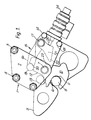
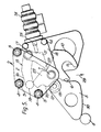
- Figures 1 to 6 show the mechanism diagrammatically from one side in six different positions of the mechanism.
- the illustrated locking mechanism which is provided on an aircraft frame for locking aircraft landing gear, incorporates a mounting unit 1 having two side plates, of which only the side plate 2 is visible in the figures, and nuts 3 and bolts 4 interconnecting the side plates.
- the mounting unit 1 is fixed to the aircraft frame.
- a guide plate 5 having a recess 6 is positioned between the side plates of the mounting unit 1 and is mounted on a pivot pin 7 so as to be rockable with respect to the mounting unit 1.
- the recess 6 is provided to receive either a downlock pin 8 or an uplock pin 9 of the aircraft landing gear.
- An engaging plate 10 is also mounted on the pivot pin 7 so as to be capable of limited pivotal movement with respect to the mounting unit 1 and also with respect to the guide plate 5.
- the engaging plate 10 has a hook portion forming a detent 11 shaped to engage the pin 8 or 9 to lock the pin 8 or 9 within the recess 6 when the engaging plate 10 is in a locked position as shown in Figures 1 and 4.
- the movement of the engaging plate 10, which has a recessed portion 12, is limited by means of a stop pin 13 on the guide plate 5.
- the mechanism includes a latch 15 comprising a latching arm 16 pivotally mounted on the guide plate 5 by means of a pivot pin 17 extending through the guid plate 6 and a cover plate 18 fixed to the guide plate by bolts 14.
- the latching arm 15 has a latch pin 19 at one end adapted to be received within a cut-out 20 in the edge of the engaging plate 10 to hold the engaging plate 10 in its locked position as shown in Figures 1 and 4.
- the pin 19 is urged into cut-out 20 by a spring (not shown) mounted between plate 10 and arm 16.
- a rocker 21 is also mounted on the pivot pin 17 so as to be pivotable with the latching arm 16.
- the rocker 21 has a foot portion 22 which can engage a shoulder 23 of the engaging plate 10 so as to pivot the latching arm 16 into its latching position.
- a hydraulic jack 24 is fixed to one edge of the guide plate 5 and has an actuator 25 which is displaceable under hydraulic control so as to pivot the rocker 21 and latching arm 16 about the pivot pin 17.
- Figure 1 shows the mechanism in the downlock positon with the downlock pin 8 locked within the recess 6 in the guide plate 5 so as to lock the landing gear in its fully lowered position.
- the downlock pin 8 may project from one side of the upper link of a folding sidestay (not shown) of the landing gear.
- Indicator switches (not shown) actuated by the latching arm 16 may serve to provide an electrical indication that the mechanism is in the locked position. In this position both of plates 5 and 10 are capable of limited rocking movements with respect to the unit 1 so that the locking mechanism is relatively immune to the effects of air frame deflection.
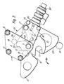
- the downlock pin 8 is released from the recess 6 by actuating the hydraulic jack 24 so that the latching arm 18 and the rocker 21 are pivoted in a clockwise direction.
- the downlock pin 8 now acts against the engaging plate 10 causing counter-clockwise pivoting of the engaging plate 10 under the effect of the downward force exerted by the downlock pin 8.
- the downlock pin 8 is thereby freed from the detent 11 and leaves the recess 6 in the direction of the arrow 26 as shown in Figure 2.
- the uplock pin 9 engages a camming edge 27 of the guide plate 5 as also shown in Figure 2.
- the uplock pin 9 may form an extension of a pivot pin coupling the folding sidestay to the leg (not shown) of the landing gear.
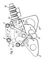
- the uplock pin 9 travels along the camming edge 27 and, in so doing, pivots the guide plate 5 counter-clockwise, together with the hydraulic jack 24, the engaging plate 10 and associated assembly, with respect to the mounting unit 1. Such pivoting continues until the uplock pin 9 enters the recess 6 as shown in Figure 3. The pin 9 thereby engages a portion 28 of the engaging plate 10 and pivots the engaging plate 10 clockwise with respect to the guide plate 5.
- a sequencing valve (not shown) is operated to reverse the hydraulic supply to the hydraulic jack 24 and cause retraction of the actuator 25.
- the latch pin 19 rides along the engaging plate 10 pivoting the latch 15. This resutls in corresponding pivoting of the latching arm 16 to engage the latch pin 19 within the cut-out 20 so as to lock the uplock pin 9 within the recess 6, as shown in Figure 4, for locking of the landing gear in its fully retracted position.
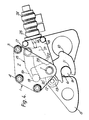
- the locked position of the mechanism as shown in Figure 4 corresponds to the locked positon as shown in Figure 1 except that the complete guide plate 5 and associated assembly is at a different orientation in the two figures corresponding to the required orientations for locking of the lowered landing gear by means of the downlock pin 8 and for locking of the retracted landing gear by means of the uplock pin 9.
- the downlock pin 8 travels along the camming edge 30 and, in so doing, pivots the guide plate 5 clockwise with respect to the mounting unit 1, as shown in Figure 6 (which shows the guide plate 5 in a position intermeditae to its two extreme orientations).
- Figure 6 which shows the guide plate 5 in a position intermeditae to its two extreme orientations.
- the guide plate 5 is pivoted to a position as shown in Figure 1, and the downlock pin 8 is locked within the recess 6 in a manner directly analogous to that described above with reference to locking of the uplock pin 9 within the recess 6.
- a single hydraulic jack is provided which is mounted on the guide plate enabling the jack to actuate the latch in both the downlock position and the uplock position of the mechanism.
- two hydraulic jacks are mounted on the mounting unit and are each arranged to actuate the latch in a respective on of the downlock and uplock positions.
- a single hydraulic jack is mounted on the mounting unit and a push-pull connection is established between the jack actuator and one end of a lever, one end of the lever being arranged to actuate the latch in the downlock position and the other end of the lever being arranged to actuate the latch in the uplock position.
- no separate frequencing valve is required for control of the hydraulic jack.
Landscapes
- Engineering & Computer Science (AREA)
- Mechanical Engineering (AREA)
- Aviation & Aerospace Engineering (AREA)
- Lock And Its Accessories (AREA)
- Forklifts And Lifting Vehicles (AREA)
Applications Claiming Priority (2)
| Application Number | Priority Date | Filing Date | Title |
|---|---|---|---|
| GB868625505A GB8625505D0 (en) | 1986-10-24 | 1986-10-24 | Locking mechanisms |
| GB8625505 | 1986-10-24 |
Publications (2)
| Publication Number | Publication Date |
|---|---|
| EP0265197A2 true EP0265197A2 (fr) | 1988-04-27 |
| EP0265197A3 EP0265197A3 (fr) | 1989-10-25 |
Family
ID=10606257
Family Applications (1)
| Application Number | Title | Priority Date | Filing Date |
|---|---|---|---|
| EP87309194A Withdrawn EP0265197A3 (fr) | 1986-10-24 | 1987-10-19 | Ensemble de verrouillage |
Country Status (2)
| Country | Link |
|---|---|
| EP (1) | EP0265197A3 (fr) |
| GB (1) | GB8625505D0 (fr) |
Cited By (15)
| Publication number | Priority date | Publication date | Assignee | Title |
|---|---|---|---|---|
| EP0384919A1 (fr) * | 1989-02-27 | 1990-09-05 | Feinmechanische Werke Mainz GmbH | Dispositif de griffe et de verrouillage pour des trappes ou trains d'alterrissage des avions |
| FR2683254A1 (fr) * | 1991-11-06 | 1993-05-07 | Messier Bugatti | Dispositif de verrouillage de securite a crochet basculant. |
| RU2122964C1 (ru) * | 1998-06-15 | 1998-12-10 | Акционерное общество открытого типа "ОКБ Сухого" | Механизм управления выпуском шасси летательного аппарата |
| WO2000048903A1 (fr) * | 1999-02-16 | 2000-08-24 | Bae Systems Plc | Mecanisme de verrouillage d'atterrisseur d'aeronef |
| FR2836669A1 (fr) * | 2002-03-04 | 2003-09-05 | Messier Bugatti | Dispositif d'accrochage, notamment pour l'accrochage d'un train d'atterrissage d'aeronef ou d'une trappe de train d'atterrissage d'aeronef |
| FR2836668A1 (fr) * | 2002-03-04 | 2003-09-05 | Messier Bugatti | Dispositif d'accrochage, notamment pour l'accrochage d'un train d'atterrissage d'aeronef ou d'une trappe de train d'atterrissage d'aeronef, et procede de fonctionnement dudit dispositif |
| WO2006081664A1 (fr) * | 2005-02-03 | 2006-08-10 | Héroux-Devtek Inc. | Ensemble de liberation de verrou de remplacement |
| JP2009274715A (ja) * | 2008-05-16 | 2009-11-26 | Ge Aviation Systems Ltd | ロック装置および航空機 |
| US7959195B2 (en) * | 2005-03-21 | 2011-06-14 | Goodrich Actuation Systems Limited | Lock arrangement |
| US8814094B2 (en) | 2008-04-04 | 2014-08-26 | Tactair Fluid Controls, Inc. | Locking mechanism with bi-modal actuator |
| GB2518007A (en) * | 2013-09-10 | 2015-03-11 | Messier Dowty Ltd | Lock and aircraft landing gear assembly |
| CN107600394A (zh) * | 2017-09-08 | 2018-01-19 | 中航飞机起落架有限责任公司 | 一种起落架电动上位锁装置 |
| GB2561383A (en) * | 2017-04-13 | 2018-10-17 | Airbus Operations Ltd | Aircraft uplock |
| CN114555464A (zh) * | 2019-10-17 | 2022-05-27 | 赛峰起落架系统公司 | 设有保持检测装置的上位锁 |
| US11498662B2 (en) | 2019-10-09 | 2022-11-15 | Goodrich Corporation | Electrically operated landing gear lock system |
Families Citing this family (1)
| Publication number | Priority date | Publication date | Assignee | Title |
|---|---|---|---|---|
| GB2581793A (en) * | 2019-02-25 | 2020-09-02 | Airbus Operations Ltd | Aircraft landing gear uplock system |
Family Cites Families (2)
| Publication number | Priority date | Publication date | Assignee | Title |
|---|---|---|---|---|
| FR1523401A (fr) * | 1967-03-22 | 1968-05-03 | Hispano Suiza Sa | Perfectionnements apportés aux dispositifs d'accrochage |
| GB2161202A (en) * | 1984-07-05 | 1986-01-08 | Dowty Rotol Ltd | Locking means for retractable devices |
-
1986
- 1986-10-24 GB GB868625505A patent/GB8625505D0/en active Pending
-
1987
- 1987-10-19 EP EP87309194A patent/EP0265197A3/fr not_active Withdrawn
Cited By (29)
| Publication number | Priority date | Publication date | Assignee | Title |
|---|---|---|---|---|
| EP0384919A1 (fr) * | 1989-02-27 | 1990-09-05 | Feinmechanische Werke Mainz GmbH | Dispositif de griffe et de verrouillage pour des trappes ou trains d'alterrissage des avions |
| FR2683254A1 (fr) * | 1991-11-06 | 1993-05-07 | Messier Bugatti | Dispositif de verrouillage de securite a crochet basculant. |
| EP0541422A1 (fr) * | 1991-11-06 | 1993-05-12 | Messier Bugatti | Dispositif de verrouillage de sécurité à crochet basculant |
| US5344197A (en) * | 1991-11-06 | 1994-09-06 | Messier-Bugatti | Safety locking device having a tilting hook |
| RU2122964C1 (ru) * | 1998-06-15 | 1998-12-10 | Акционерное общество открытого типа "ОКБ Сухого" | Механизм управления выпуском шасси летательного аппарата |
| WO2000048903A1 (fr) * | 1999-02-16 | 2000-08-24 | Bae Systems Plc | Mecanisme de verrouillage d'atterrisseur d'aeronef |
| US6279853B1 (en) | 1999-02-16 | 2001-08-28 | Bae Systems Plc | Aircraft undercarriage lock mechanism |
| FR2836668A1 (fr) * | 2002-03-04 | 2003-09-05 | Messier Bugatti | Dispositif d'accrochage, notamment pour l'accrochage d'un train d'atterrissage d'aeronef ou d'une trappe de train d'atterrissage d'aeronef, et procede de fonctionnement dudit dispositif |
| EP1342664A1 (fr) | 2002-03-04 | 2003-09-10 | Messier-Bugatti | Dispositif d'accrochage, notamment pour l'accrochage d'un train d'atterissage d'aéronef |
| EP1342663A1 (fr) | 2002-03-04 | 2003-09-10 | Messier-Bugatti | Dispositif d'accrochage et son procédé de fonctionnement, notamment pour un train d'atterrissage d'aéronef |
| US6802476B2 (en) | 2002-03-04 | 2004-10-12 | Messier-Bugatti | Latch device, in particular for latching an airplane landing gear or an airplane landing gear hatch, and a method of operating said device |
| US6811118B2 (en) | 2002-03-04 | 2004-11-02 | Messier-Bugatti | Latch device, in particular for latching an airplane landing gear or an airplane landing gear hatch |
| FR2836669A1 (fr) * | 2002-03-04 | 2003-09-05 | Messier Bugatti | Dispositif d'accrochage, notamment pour l'accrochage d'un train d'atterrissage d'aeronef ou d'une trappe de train d'atterrissage d'aeronef |
| WO2006081664A1 (fr) * | 2005-02-03 | 2006-08-10 | Héroux-Devtek Inc. | Ensemble de liberation de verrou de remplacement |
| US7959195B2 (en) * | 2005-03-21 | 2011-06-14 | Goodrich Actuation Systems Limited | Lock arrangement |
| US8814094B2 (en) | 2008-04-04 | 2014-08-26 | Tactair Fluid Controls, Inc. | Locking mechanism with bi-modal actuator |
| JP2009274715A (ja) * | 2008-05-16 | 2009-11-26 | Ge Aviation Systems Ltd | ロック装置および航空機 |
| GB2518007A (en) * | 2013-09-10 | 2015-03-11 | Messier Dowty Ltd | Lock and aircraft landing gear assembly |
| GB2523899A (en) * | 2013-09-10 | 2015-09-09 | Messier Dowty Ltd | Lock and aircraft landing gear assembly |
| GB2518007B (en) * | 2013-09-10 | 2015-11-04 | Messier Dowty Ltd | A lock and aircraft landing gear assembly |
| GB2523899B (en) * | 2013-09-10 | 2016-01-20 | Messier Dowty Ltd | A lock and aircraft landing gear assembly |
| US10569863B2 (en) | 2013-09-10 | 2020-02-25 | Safran Landing Systems Uk Ltd | Lock and aircraft landing gear assembly |
| US11242137B2 (en) | 2013-09-10 | 2022-02-08 | Safran Landing Systems Uk Ltd | Lock and aircraft landing gear assembly |
| GB2561383A (en) * | 2017-04-13 | 2018-10-17 | Airbus Operations Ltd | Aircraft uplock |
| CN110582445A (zh) * | 2017-04-13 | 2019-12-17 | 空中客车营运有限公司 | 飞行器上位锁 |
| US11492136B2 (en) | 2017-04-13 | 2022-11-08 | Airbus Operations Limited | Aircraft uplock |
| CN107600394A (zh) * | 2017-09-08 | 2018-01-19 | 中航飞机起落架有限责任公司 | 一种起落架电动上位锁装置 |
| US11498662B2 (en) | 2019-10-09 | 2022-11-15 | Goodrich Corporation | Electrically operated landing gear lock system |
| CN114555464A (zh) * | 2019-10-17 | 2022-05-27 | 赛峰起落架系统公司 | 设有保持检测装置的上位锁 |
Also Published As
| Publication number | Publication date |
|---|---|
| EP0265197A3 (fr) | 1989-10-25 |
| GB8625505D0 (en) | 1986-11-26 |
Similar Documents
| Publication | Publication Date | Title |
|---|---|---|
| EP0265197A2 (fr) | Ensemble de verrouillage | |
| US8814094B2 (en) | Locking mechanism with bi-modal actuator | |
| US5547130A (en) | Lock for an engine thrust reverser | |
| EP0580352A1 (fr) | Dispositif de verrouillage d'inverseur de poussée | |
| JPH02240U (fr) | ||
| EP3025362B1 (fr) | Système de commande de train d'atterrissage | |
| GB2039986A (en) | Device with independent hooks and automatic locking mechanism for hooking up loads under aircraft | |
| WO2002049873A3 (fr) | Commande externe d'un ensemble inclinable | |
| US4573649A (en) | Integrated alternate gear extension and ground-crew door opening/closing system for an aircraft | |
| US5475190A (en) | Operator of a handle or toggle of a switch | |
| US2937541A (en) | Fail-safe up lock mechanism | |
| CN108529454B (zh) | 用于吊臂收纳的吊臂联接系统 | |
| EP3938861B1 (fr) | Levier de vitesse de véhicule muni d'une came à bascule avec verrou neutre | |
| EP0292620B1 (fr) | Dispositif commandé par pédale | |
| EP1912861B1 (fr) | Dispositif de sécurisation pour système de chargement dans le compartiment de soute d un avion, comprenant au moins un loquet de sécurisation | |
| US2823551A (en) | Lifting jack | |
| CN111498081B (zh) | 用于飞行器部段的门组件 | |
| CN219451992U (zh) | 多功能梯内外梯的快速锁定机构 | |
| US2570586A (en) | Gust lock | |
| JPH05177569A (ja) | 自動工具交換用カップラー | |
| US4601454A (en) | Telescopic supporting post | |
| US3519111A (en) | Manual selector arrangement for an automatic gear box | |
| GB2082236A (en) | Mine roof support with cantilever extension on roof plate | |
| US2458845A (en) | Landing mechanism for airplanes | |
| JPH0120400Y2 (fr) |
Legal Events
| Date | Code | Title | Description |
|---|---|---|---|
| PUAI | Public reference made under article 153(3) epc to a published international application that has entered the european phase |
Free format text: ORIGINAL CODE: 0009012 |
|
| AK | Designated contracting states |
Kind code of ref document: A2 Designated state(s): DE ES FR GB IT |
|
| PUAL | Search report despatched |
Free format text: ORIGINAL CODE: 0009013 |
|
| AK | Designated contracting states |
Kind code of ref document: A3 Designated state(s): DE ES FR GB IT |
|
| STAA | Information on the status of an ep patent application or granted ep patent |
Free format text: STATUS: THE APPLICATION IS DEEMED TO BE WITHDRAWN |
|
| 18D | Application deemed to be withdrawn |
Effective date: 19900426 |
|
| RIN1 | Information on inventor provided before grant (corrected) |
Inventor name: BENNETT, IAN ROBERT |