EP0265267A2 - Automatische Nadelfadenzuführeinrichtung auf einer Nähmaschine - Google Patents
Automatische Nadelfadenzuführeinrichtung auf einer Nähmaschine Download PDFInfo
- Publication number
- EP0265267A2 EP0265267A2 EP87309359A EP87309359A EP0265267A2 EP 0265267 A2 EP0265267 A2 EP 0265267A2 EP 87309359 A EP87309359 A EP 87309359A EP 87309359 A EP87309359 A EP 87309359A EP 0265267 A2 EP0265267 A2 EP 0265267A2
- Authority
- EP
- European Patent Office
- Prior art keywords
- thread
- needle
- needle thread
- thread supply
- take
- Prior art date
- Legal status (The legal status is an assumption and is not a legal conclusion. Google has not performed a legal analysis and makes no representation as to the accuracy of the status listed.)
- Granted
Links
- 230000033001 locomotion Effects 0.000 claims abstract description 51
- 238000009958 sewing Methods 0.000 claims abstract description 32
- 239000004744 fabric Substances 0.000 claims abstract description 25
- 230000007246 mechanism Effects 0.000 claims description 16
- 230000001276 controlling effect Effects 0.000 claims description 14
- 230000004044 response Effects 0.000 claims description 3
- 238000006073 displacement reaction Methods 0.000 description 9
- 230000000875 corresponding effect Effects 0.000 description 5
- 230000004048 modification Effects 0.000 description 4
- 238000012986 modification Methods 0.000 description 4
- 239000013256 coordination polymer Substances 0.000 description 3
- 238000001514 detection method Methods 0.000 description 3
- 229920000136 polysorbate Polymers 0.000 description 2
- 230000001105 regulatory effect Effects 0.000 description 2
- 229940000425 combination drug Drugs 0.000 description 1
- 230000006835 compression Effects 0.000 description 1
- 238000007906 compression Methods 0.000 description 1
- 238000010276 construction Methods 0.000 description 1
- 230000003247 decreasing effect Effects 0.000 description 1
- 230000001419 dependent effect Effects 0.000 description 1
- 238000010586 diagram Methods 0.000 description 1
- 230000006870 function Effects 0.000 description 1
- 230000006872 improvement Effects 0.000 description 1
- 230000003993 interaction Effects 0.000 description 1
- 230000002787 reinforcement Effects 0.000 description 1
- 230000001502 supplementing effect Effects 0.000 description 1
Images



Classifications
-
- D—TEXTILES; PAPER
- D05—SEWING; EMBROIDERING; TUFTING
- D05B—SEWING
- D05B51/00—Applications of needle-thread guards; Thread-break detectors
Definitions
- the present invention relates to a sewing machine capable of automatic needle thread supply control, and more particularly, to improvement in the same which includes a pair of thread clamp members that make a needle thread free to pass and clamped with predetermined timings between a thread supply source and a thread take-up lever in a path leading from the thread supply source to a needle, and a thread passage control means which controls so that at least one of releasing speed and clamping speed may be in proportion to a rotational speed of an arm shaft.
- the take-up lever driven vertically in timed with rotation of the arm shaft performs supplying a needle thread toward a bobbin when the lever descends and also performs tightening a needle thread loop made at a needle eye and supplementing a predetermined amount of the needle thread from a thread supply spool when the lever ascends.
- a thread controller that provides the needle thread with passage resistance to enable tightening of the needle thread loop.
- This needle thread controller has a pair of thread control discs contacting each other under pressure of a compression spring and exerts a frictional resistance on a needle thread passing through between the pair of the thread control discs.
- the needle thread is supplied under interaction of tension that acts on the needle thread following the thread controller and resistive force of thread controller, therefore it is difficult to exactly control the force of tightening the needle thread and supply quantity of the needle thread and it is also difficult to adjust the needle thread control of stitches in response to thicknesses and types of work fabrics (that is, thickness and type of the needle thread to be selected according to these factors).
- an electrically actuated needle thread passage control device which comprises, in place of the above mentioned spring actuated thread controller, a pair of the thread control discs that contact under pressure of a solenoid actuator, and which allows the needle thread to pass at a predetermined timing during a given time period and does not allow to pass during a period except the above by driving the actuator in timed with the arm shaft rotation.
- this control device performs the same tightening of the needle thread and supplies the same quantity of the thread regardless of a thick or a thin thread and can not tighten the thread so as to generate tension corresponding to the thread thickness. This results in unstable thread control.
- the present invention is an invention in combination with a sewing machine having a needle thread supply source, an endwise reciprocatory needle with an eye, a feed member operating in synchronism with the reciprocation of the needle for imparting a feed motion to a work fabric, a take-up member movable between a first position where the needle thread is slackened to a maximum thread slack amount and a second position where the needle thread is taken up to a maximum thread take-up amount, and a needle thread supply path extending from the needle thread supply source through the take-up member to the eye of the needle, by providing an automatic needle thread supply control system comprising: thread securing means operative in synchronism with the reciprocation of the needle for securing the maximum thread take-up amount of the needle thread during a specific period which starts at a time determined so as to at least partly overlap with the period of the feed motion and terminates at a time when the eye of the needle is lowered near to the
- the present invention also is an invention in combination with a sewing machine having the same constitution as that of abovementioned aspect of the invention, by providing an automatic needle thread supply control system comprising: driving means for timing the start of holding the take-up member at the second position so that the period of holding the take-up member at the second position at least partly overlaps with the period of the feed motion, holding the take-up member at the second position until the eye of the needle is lowered near to the surface of a bed, and moving the take-up member in sychronism with the reciprocation of the needle after the eye of the needle has been lowered near to the surface of the bed; thread supply stopping means operative to permit and check the supply of the needle thread which is drawn out from the needle thread supply source as the fabric is fed by the feed member; and control means operative in synchronism with the reciprocation of the needle for controlling the timing and the period of operation of the thread supply stopping means according to the thickness of the fabric being sewn or the thickness of the needle thread being used so that the thread supply stopping means permits the supply
- the control means determines the timing of actuation and the period of operation of the thread supply stopping means according to the thickness of the fabric or the thickness of the needle thread every vertical movement of the needle and, while being actuated, the thread supply stopping means permits the free supply of the needle thread from the thread supply source to the take-up member.
- the take-up member is held at the maximum thread take-up position (second position), and thereby the fixed length of the thread stored by the loop taker is secured without being used for forming a stitch.
- an optimum length of the needle thread spontaneously determined according various stitching conditions, such as the type of fabric and stitch length, is supplied from the thread supply source.
- the take-up member After the period of actuation of the thread supply stopping means has elapsed the take-up member starts its motion in phase with the vertical reciprocatory motion of the needle upon the arrival of the eye of the needle at a position near the surface of the bed.
- the take-up member moves toward the maximum thread slackening position (first position)
- the needle thread is supplied to the loop taker, and then the needle thread and the bobbin threads are interlocked through the known motion of the loop taker.
- the point of interlock of the needle thread and the bobbin thread is completed at a moment when the take-up member arrives at the maximum thread take-up position after the needle thread and the bobbin thread has been interlocked.
- the thread supply stopping means comprises a pair of thread clamping members having clamping surfaces which engage in point contact to surely clamp the needle thread.
- control means comprises proportional control means operatively connected to the main shaft of the sewing machine to control the speed of at least either a motion for engaging or a motion for disengaging the thread clamping member of the thread supply stopping means in proportion to the rotating speed of the main shaft of the sewing machine.
- the proportional control means may comprise a rotary member operatively connected to the main shaft of the sewing machine, a detector for generating a pulse signal every predetermined angle of rotation of the rotary member, and actuating means for varying the relative position of the thread clamping members in response to the pulse signal at least either in engaging or in disengaging the thread clamping members.
- the proportional control means engages and disengages the thread clamping members through a smooth and continuous motion at a speed proportional to the rotating speed of the main shaft of the sewing machine. Accordingly, the phase of clamping the needle thread and the phase of the releasing the needle thread vary according to the thickness of the needle thread. That is, a thick needle thread, as compared with a thin needle thread, is clamped at an earlier phase and is released at a later phase, and hence a thick needle thread of a less length is supplied for forming a stitch, so that a higher tension is exerted on the loop to tighten the loop, where as a thin needle thread of a more length is supplied and a lower tension is exerted to the thin needle thread for tightening the loop.
- the tension of the needle thread is controlled stably according to the thickness of the needle thread and the rotating speed of the main shaft of the sewing machine.
- the present invention is also an invention in combination with a sewing machine having a needle thread supply source, an endwise reciprocatory needle with an eye, a take-up member movable between a maximum thread slack position and a maximum thread take-up position, and a needle thread supply path extending from the needle thread supply source through the take-up member to the eye of the needle, by providing an automatic needle thread supply control system comprising: a pair of thread clamping members movable toward and away from each other for checking and permitting the supply of the needle thread from the needle thread supply source toward the take-up; and proportional control means for controlling the speed of at least either a motion for engaging or a motion for disengaging the thread clamping members in proportion to a sewing speed; whereby the timing and the period of checking and permitting the supply of the needle thread are automatically changed according to the thickness of the needle thread being used.
- the proportional control means may comprise a cam member operatively connected to the main shaft of the sewing machine and a cam follower engageable with the cam member and operatively connected to one of the thread clamping members.
- the present invention is also an invention in combination with a sewing machine having a needle thread supply source, an endwise reciprocatory needle with an eye, and a needle thread supply path extending from the needle thread supply source and to the eye of the needle and including at least one bent portion, by providing an automatic needle thread supply control system comprising: a pair of thread contacting members located at the bent portion of the needle thread supply path and movable toward and away from each other in a specific direction which is substantially parallel to a plane including the needle thread supply path about the bent portion; and control means for controlling the movement of the thread contacting members to vary an amount of the needle thread to be supplied toward the eye of the needle.
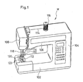
- Fig. 1 illustrates an electronic lock stitch sewing machine M incorporating a embodiment of the present invention. Illustrated in Fig. 1 are bed 102, a standard 104 extending upright from the right end of the bed 102, and an arm 106 horizontally extending from the upper end of the standard 104, overhanging the bed 102 and having a head 108 at the left end thereof.
- a needle bar 110 and a presser bar 118 are provided in the head 108.
- a needle 112 is attached to the lower end of the needle bar 110.
- the needle bar 110 is driven for vertical reciprocatory motion and for lateral jogging motion by the arm shaft 128 of the sewing machine.
- a presser foot 120 is attached to the lower end of the presser bar 118.
- the presser bar 118 is raised or lowered by means of an operating member (not shown).
- a throat plate 122 is provided on the bed 102, and a feed dog 123 is provided in the bed 102 so as to be moved upward through slots formed in the throat plate 122 by a feed mechanism.
- Predetermined stitches are formed in a work fabric through the cooperative operation of the needle bar 110 and the feed mechanism including the feed dog 123. Since the feed mechanism is of an ordinary know constitution, the description thereof will be omitted.
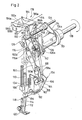
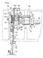
- Fig. 2 to 4 illustrate internal mechanisms disposed within the head 108 and part of the arm 106 near the hear 108 of the sewing machine M.
- the needle 112 is attached to the lower end of the needle bar 110, while the needle bar 110 is supported vertically movably by a needle bar support 124.
- the needle bar support 124 is supported pivotally at the upper end thereof with a pin 126 on the frame so as to jog laterally.
- the needle bar 110 is driven by the arm shaft 128 and a needle bar crank 130 secured to the free end of the arm shaft 128 for vertical motion relative to the needle bar support 124.
- the presser foot 120 is attached detachably to the lower end of the presser bar 118, while the presser bar 118 is secured to the frame by a mechanism (not shown) so as to be moved between an upper position and a lower position.
- a mechanism not shown
- the presser foot 120 presses a work fabric against the throat plate 122.
- the arm shaft 128 is supported rotatably in a bearing bush 132 or the like on the frame.
- An auxiliary shaft 134 is disposed above and beyond the arm shaft 128 so as to extend in parallel to the same.
- the auxiliary shaft 134 is journaled on the frame.
- a swing lever 136 is supported swingably at one end thereof on the auxiliary shaft 134.
- the swing lever 136 extends from the auxiliary shaft 134 to the left side of a take-up lever crank 138 fixedly mounted on the arm shaft 128.
- the crank pin 140 of the take-up lever crank 138 extend through a slot cam 142 formed in the swing lever 136.
- a connecting plate 144 is fixed to the left end of the crank pin 140.
- the needle bar crank 130 is connected rotatably to the connecting plate 144 with a pin 146 extending leftward from the connecting plate 144.
- the needle bar crank 130 is connected at the lower end thereof to the middle part of the needle bar 110.
- the upper part of the swing lever 136 is bent in a zigzag shape to form a take-up lever 148 (take-up member) which extends upward.
- a thread guide hole 148a is formed at the free end of the take-up lever 148.
- the slot cam 142 of the swing lever 136 consists of a circular arc section 142a having a radius of curvature coinciding with the radius of the circular locus of the crank pin 140 and permitting the rotation of the crank pin 140 through an angle of approximately 74° in a range about the uppermost position of the crank pin 140, and short straight sections 142b extending from the opposite ends of the circular arc section 142a, respectively.
- the slot cam 142 is reinforced along the periphery thereof with a reinforcement 136a.
- the take-up lever 148, the needle 112 attached to the lower end of the needleb ar 110 and the feed dog 123 of th feed mechanism perform motions represented by motion curves MA, MB and MD as functions as the phase angle of the arm shaft 128 as a parameter in Fig. 5, respectively.
- the take-up lever 148 is held at the uppermost position from a time after the arm shaft 128 has turned through an angle of approximately 40° from the start of the feed motion to a time when the eye of the needle 112 arrives at the upper surface of the throat plate 122. Accordingly, the take-up lever 148 is held at the upper most position substantially during the feed motion except the initial stage of the feed motion.
- the swing lever 136 may be designed so that the take-up lever 148 is held at the upper most position from the start of the feed motion. In either case, the swing lever 136 of the second embodiment is comparatively simple in construction and is able to operate smoothly and silently.
- a thread supply control mechanism will be described hereinafter with reference to Figs. 2 to 7.
- a plate member 150 forming part of the frame is disposed near and on the left hand side of the needle bar crank 130 disposed on the left hand side of the arm shaft 120.
- the plate member 150 extends at right angles to the arm shaft 128.
- a pre-tension device 152 for exerting a tension to the needle thread 114 is provided, when necessary, on the left side of the plate member 150 slightly before the arm shaft 128.
- the pre-tension device 152 has a pair of tension discs 152a which exert a tension to the needle thread passing therebetween. The tension of the needle thread is adjusted by regulating spring force applied to the tension discs 152a by operating a dial. The pre-tension device 152 may be omitted.
- a thread supply control device 154 which clamps or releases the needle thread 114 in synchronism with the rotation of the arm shaft 128 is provided in a thread path between a thread supply spool 116 and the thread guide hole 148a of the take-up lever 148.
- the thread supply control device 154 comprises a thread guide plate 156, and a swing lever 158 provided with a thread clamping wheel 164.
- the thread guide plate 156 (thread clamping member) is secured to the left side of the plate member 150 at a position below the pre-tension device 152.
- the swing lever 158 is disposed adjacent to the left side of the thread guide plate 156 and is pivotally attached to the plate member 150 with a hinge screw 162.
- a link plate 160 also is pivotally attached at the lower end thereof to the plate member 150 with the hinge screw 162.
- the thread clamping wheel 164 (thread clamping member) held on the swing lever 158 engages the thread clamping edge 156a of the thread guide plate 156 to clamp the needle thread 114 between the thread clamping edge 156a and the thread clamping wheel 164.
- the swing lever 158 is biased resiliently by a spring 166 having one end connected to the frame and the other end connected to the swing lever 158 so that the thread clamping wheel 164 is pressed against the thread clamping edge 156a.
- a contact wheel 168 attached to the upper end of the arm 158a of the swing lever 158 is in contact with the front surface of a contact lug 160a formed near the lower end of the link plate 160.
- an annular V-shaped groove 164a is formed in the circumference of the thread clamping wheel 164, while the thread clamping edge 156a of the thread guide plate 156 is formed in a U-shaped curve opening downward in a side view and in a U-shape in section.
- the V-shaped groove 164a of the thread clamping wheel 164 and the U-shaped thread clamping edge 156a of the thread guide plate engage to clamp the needle thread 114 therebetween.
- the needle thread 114 After passing the pre-tension device 152, the needle thread 114 is turned by the U-shape thread clamping edge 156a of the thread guide plate 156, and is guided via the thread guide hole 148a of the take-up lever 148 to the needle 112.
- the thread clamping edge 156a and the V-shaped groove 164a are engaged, the needle thread 114 is clamped firmly between the thread clamping edge 156a and the V-shape groove 164a at two points.
- the thread clamping wheel 164 is moved in parallel to a plane including the thread supply path returned at the thread clamping edge 156a and the thread clamping wheel 164 clamps the needle thread 114 across the same, a very high clamping pressure is applied the the needle thread 114. That is, if the thread clamping wheel 164 is pressed with a small force against the thread clamping edge 156a, the needle thread 114 can firmly be clamped.
- a rotary arm 170 having an elliptic cam groove 172 is fixedly mounted on the arm shaft 128 at a position opposite the right end of the auxiliary shaft 134, and a cam follower 174a attached to the free end of a first arm 174 engages the cam groove 172.
- a second arm 176 is fixedly mounted to the auxiliary shaft 134 at the left end of the same.
- a pin 176a attached to the free end of the second arm 176 is received in a slot 160b formed in the upper end of the link plate 160 to interconnect the second arm 176 and the link plate 160.
- the needle thread 114 is clamped between the thread guide plate 156 and the thread clamping wheel 164 so that the needle thread 114 is surely tightened.
- the swing lever 158 is driven in phase with the feed motion to release and supply the needle thread 114. While the needle thread 114 is thus released free, the feed motion and the needle jogging motion are accomplished, and then the needle thread 114 is clamped again before the needle 112 arrives at the throat plate 122. While the needle thread 114 is clamped, the stitching motion is carried out to form a needle thread loop by the shuttle.
- the needle thread of an amount necessary for feeding the work fabric and for jogging the needle 112 is surely supplied, while the needle thread 114 is not supplied uselessly while a loop of the needle thread 114 is formed, because the needle thread 114 is clamped during the loop forming period.
- the respective speed of the upward swing and downward swing of the first arm 174 are proportional to the rotating speed of the arm shaft 128, so that the needle thread clamping wheel 164 is moved toward and away from the thread clamping edge 156a at a speed proportional to the rotating speed of the arm shaft 128.
- a substantially fixed amount of the needle thread 114 is supplied in every stitching cycle regardless of the rotating speed of the arm shaft 128, and hence the tension of the needle thread in forming stitches is not affected by the stitching speed.
- a needle thread supply mechanism 178 which draws out the needle thread 114 from the thread supply spool 116 by a predetermined amount and stores the same while the take-up lever 148 is moved downward and the needle thread 114 is clamped between the needle thread clamping wheel 164 and the needle thread guide plate 156 will be described herinafter with reference to Figs. 2 to 4.
- a sleeve 180 is fitted rotatably on the auxiliary shaft 134 near a position where the auxiliary shaft 134 supports the swing lever 136 at one end, and the end of the swing lever 136 on the auxiliary shaft 134 is fixed to the sleeve 180.
- An L-shaped arm 182 having a thread catching hook 182a at the free end thereof is fixed to the sleeve 180.
- a thread guide member 184 substantially of a U-shape in front view is disposed on top of the left end of the arm 106 of the sewing machine M.
- the thread guide member 184 has a top wall 184a, a first guide wall 184b and a second guide wall 184c.
- the first guide wall 184b and a second guide wall 184c extend vertically downward from the opposite sides of the top guide wall 184a, respectively.
- the second guide wall 184c of the thread guide member 184 is fixed to the upper end of the plate member 150 with a screw 186.
- the thread guide member 184 is disposed near and above the L-shape arm 182.
- the first guide wall 184b and the second guide wall 184c are disposed opposite to each other with a predetermined distance therebetween.
- a first guide slit 188a and a second guide slit 188b are formed laterally opposite to each other in the first guide wall 184b and the second guide wall 184c, respectively.
- the respective rear ends of the first guide slit 188a and the second guide slit 188b are open to receive the needle thread 114 therein.
- a third guide slit 190 is formed in the upper part of the front end of the second guide wall 184c.
- the needle thread 114 pulled out from the thread supply spool 116 is extended sequentially through the first guide slit 188a, the second guide slit 188b, along the left side of the second guide wall 184c, via the third guide slit 190, the pre-tension device 152, the thread clamping edge 156a of the thread guide plate 156, where the needle thread 114 is returned upward, and then further through the thread guide hole 148a of the take-up lever 148, and thread guides 192 and 194 to the eye of the needle 112.
- Both the L-shape arm 182 and the swing lever 136 are fixed to the sleeve 180, and hence the L-shaped arm 182 and the swing lever 136 are driven for swing motion by the take-up lever crank 138 in phase with the rotation of the arm shaft 128.
- the take-up lever 148 is held at the uppermost position as indicated by continuous lines
- the L-shaped arm 182 is located, as indicated by dotted lines, behind the needle thread 114 passing the respectively front ends of the first guide slit 188a and the second guide slit 188b.
- the needle thread 114 is pulled out from the thread supply spool 116 by the L-shaped arm 182 of the needle thread supply mechanism 178, so that the needle thread 114 between the thread supply spool 116 and the thread clamping edge of the thread guide plate 156 is slackened.
- the take-up lever 148 is moved upward to tighten the needle thread 114, when the needle thread 114 is released from the restrain of the thread guide 156 and the thread clamping wheel 164, and then the needle thread 114 of a necessary amount is supplied via the take-up lever 148 to the needle 112 as the feed dog 123 performs the feed motion and the needle 112 is jogged.
- the feed motion of the feed dog 123 is started before the needle thread 114 is released, the amount of the needle thread 114 required for such a mode of feed motion is supplemented by the elastic extension of the needle thread 114, and the needle thread 114 is recovered from the elastic extension as the same is supplied after being released.
- the phases of the needle thread clamping and releasing operations are controlled automatically according to the thickness of the needle thread 114, and the needle thread 114 of a necessary amount dependent on the feed stroke and the needle jogging stroke is surely supplied for every stitching cycle. Accordingly, an optimum tension according to the thickness of the needle thread 114 is exerted to the needle thread 114.
- a U-shaped groove 164b may be formed in the circumference of the thread clamping wheel 164, as illustrated in Fig. 8, the thread clamping wheel 164 may be moved obliquely relative to the thread guide plate 156 as illustrated in Fig. 9, or the needle clamping wheel 164 may have a cylindrical circumference as illustrated in Fig. 10.
- a member secured to the swing lever 158 may be employed instead of the thread clamping wheel 164.
- the needle thread 114 is wound around the half of the circumference of the free wheel 156A, and a clamping member 164A substituting the thread clamping wheel 164 is brought into point-contact with the circumference of the free wheel 156A to clamp the needle thread as illustrated in Fig. 11.
- the thread supply control device 154A comprises the thread clamping wheel 164, a linear actuator 200 for driving the thread clamping wheel 164, a displacement sensor 201 for sensing the displacement of the thread clamping wheel 164, a phase angle sensor 202 for sensing the phase angle of the arm shaft 128, at timing sensor 203, and a control unit 204.
- the linear actuator 200 comprises a moving coil 205 connected to the thread clamping wheel 164, a metallic frame 206 vertically movably retaining the moving coil 205 and forming a magnetic path, and a permanent magnet 207 forming a uniform magnetic field around the moving coil 205.
- the vertical position of the moving coil is determined according to the intensity of current supplied to the moving coil 205.
- the displacement sensor 201 is a potentiometer comprising a contact 209 connected to the thread clamping wheel supporting member 208 of the moving coil 205, and electric resistor 210 connected to a reference voltage line.
- the phase angle sensor 202 comprises, for example, a disc having a plurality of slits formed along the circumference thereof at regular angular intervals and fixed to the arm shaft 128, and a photoelectric detector comprising a light emitting element and a light receiving element for detecting the slits.
- the timing sensor 203 is a limit switch or a contactless switch which detects the arrival of the needle bar 110 at the upper most position.
- the control unit 204 comprises a central processing unit (hereinafter abbreviated to "CPU") 211, a read-only memory (ROM) 212, a random access memory (RAM) 213, an input-output interface 214, a driving circuit 215 which receives control signals through the input-output interface 214 from the CPU 211 and supplied a driving current corresponding to the input signal to the moving coil 205, and AD converter 216 which converts an analog detection signal of the displacement sensor 201 into a digital signal corresponding to the analog detection signal and given the same to the input-output interface 214.
- the detection signals of the phase angle sensor 202 and the timing sensor 203 are given through the input-output interface 214 to the CPU 211.
- the input-output interface 214, the ROM 212 and the RAM 213 are connected through an address bus and a data bus to the CPU 211.
- the ROM 212 pre-stores a control program for controlling the linear actuator 200 in accordance with a timing signal S1 given by the timing sensor 203, a phase angle signal S2 given by the phase angle sensor 202 and displacement signal given by the displacement sensor 201 ro regulate the gap between the thread clamping wheel 164 and the thread clamping edge 156a of the thread guide plate 156.
- a predetermined current is supplied to the moving coil 205 until a predetermined number of phase angle signals S2 are given to the CPU 211 after a timing signal S1 has been given to the CPU 211, and thereby the thread clamping wheel 164 is held in contact with the thread clamping edge 156a to clamp the needle thread 114 therebetween.
- the CPU 211 controls the driving circuit 215 so as to reduce the driving current at a rate corresponding to the rotating speed of the arm shaft 128 as represented by a curve IP; consequently, the moving coil 205 is lowered gradually to increase the gap between the thread clamping wheel 164 and the thread clamping edge 156a as represented by a curve CP.
- the rotating speed of the arm shaft 128 is determined through computation on the basis of the phase angle signals S2.
- Various CP curves for various rotating speeds are stored as a memory map in the ROM 212.
- the magnitude of the driving current is controlled memontly through feedback control on the basis of the displacement signals given by the displacement sensor 201 in a mode as represented by the curve IP.
- the curves CP corresponding to the rotating speed of the arm shaft 128 are stored in the memory map of the ROM 212 to regulate the rate of increasing the gap between the thread clamping wheel 164 and the thread clamping edge 156a in proportion to the rotating speed of the arm shaft 128.
- the magnitude of the driving current is controlled in the same manner to decrease the gao between the thread clamping wheel 164 and the thread clamping edge 156a in clamping the needle thread 114.
- the timing of driving the moving coil 205 is determined by counting the phase angle signals S2, and then the magnitude of the driving current supplied to the moving coil 205 is regulated through feed-back control on the basis of the displacement signals according to a curve IQ so that the gap is decreased along a curve CQ stored in the memory map of the ROM 212.
- a thin needle thread is released at a point EF1 and is clamped at a point EC1
- a thick needle thread is released at a point EF2 and is clamped at a point EF2 as shown in Fig. 13.
- the linear actuator 200 employed in this embodiment may be substituted by a stepping motor or the like.
Landscapes
- Engineering & Computer Science (AREA)
- Textile Engineering (AREA)
- Sewing Machines And Sewing (AREA)
Applications Claiming Priority (2)
| Application Number | Priority Date | Filing Date | Title |
|---|---|---|---|
| JP251333/86 | 1986-10-22 | ||
| JP25133386A JPS63105790A (ja) | 1986-10-22 | 1986-10-22 | 糸通過制御可能なミシン |
Publications (3)
| Publication Number | Publication Date |
|---|---|
| EP0265267A2 true EP0265267A2 (de) | 1988-04-27 |
| EP0265267A3 EP0265267A3 (en) | 1989-08-23 |
| EP0265267B1 EP0265267B1 (de) | 1991-05-22 |
Family
ID=17221259
Family Applications (1)
| Application Number | Title | Priority Date | Filing Date |
|---|---|---|---|
| EP19870309359 Expired EP0265267B1 (de) | 1986-10-22 | 1987-10-22 | Automatische Nadelfadenzuführeinrichtung auf einer Nähmaschine |
Country Status (3)
| Country | Link |
|---|---|
| EP (1) | EP0265267B1 (de) |
| JP (1) | JPS63105790A (de) |
| AU (1) | AU592234B2 (de) |
Cited By (1)
| Publication number | Priority date | Publication date | Assignee | Title |
|---|---|---|---|---|
| CN116024738A (zh) * | 2023-03-02 | 2023-04-28 | 湘潭大学 | 一种多层堆叠碳纤维织物单线缝合机器人 |
Families Citing this family (1)
| Publication number | Priority date | Publication date | Assignee | Title |
|---|---|---|---|---|
| JP2019166039A (ja) * | 2018-03-23 | 2019-10-03 | ブラザー工業株式会社 | ミシン |
Family Cites Families (5)
| Publication number | Priority date | Publication date | Assignee | Title |
|---|---|---|---|---|
| US3307509A (en) * | 1964-12-31 | 1967-03-07 | United Shoe Machinery Corp | Outsole sewing machines |
| US4166423A (en) * | 1978-02-28 | 1979-09-04 | The Singer Company | Adaptive sewing machine |
| US4215641A (en) * | 1979-07-05 | 1980-08-05 | The Singer Company | Electronic control of needle thread in a sewing machine |
| US4619213A (en) * | 1983-09-30 | 1986-10-28 | Tokyo Juki Industrial Co., Ltd | Drive control mechanism of sewing machine |
| JPS62155774U (de) * | 1986-03-20 | 1987-10-03 |
-
1986
- 1986-10-22 JP JP25133386A patent/JPS63105790A/ja active Pending
-
1987
- 1987-10-21 AU AU79985/87A patent/AU592234B2/en not_active Ceased
- 1987-10-22 EP EP19870309359 patent/EP0265267B1/de not_active Expired
Cited By (2)
| Publication number | Priority date | Publication date | Assignee | Title |
|---|---|---|---|---|
| CN116024738A (zh) * | 2023-03-02 | 2023-04-28 | 湘潭大学 | 一种多层堆叠碳纤维织物单线缝合机器人 |
| CN116024738B (zh) * | 2023-03-02 | 2024-04-05 | 湘潭大学 | 一种多层堆叠碳纤维织物单线缝合机器人 |
Also Published As
| Publication number | Publication date |
|---|---|
| EP0265267A3 (en) | 1989-08-23 |
| EP0265267B1 (de) | 1991-05-22 |
| JPS63105790A (ja) | 1988-05-11 |
| AU592234B2 (en) | 1990-01-04 |
| AU7998587A (en) | 1988-04-28 |
Similar Documents
| Publication | Publication Date | Title |
|---|---|---|
| US4766827A (en) | Thread measuring and feeding apparatus for a sewing machine | |
| US4632048A (en) | Method of controlling upper thread in sewing machine | |
| JP2700557B2 (ja) | 自動糸調子ミシン | |
| US4791876A (en) | Automatic needle thread supply control system | |
| US4869186A (en) | Needle thread tension control system with differential clamping | |
| EP0265267A2 (de) | Automatische Nadelfadenzuführeinrichtung auf einer Nähmaschine | |
| US4960062A (en) | Sewing machine automatic thread tension device with thread elongation detector | |
| KR20010074486A (ko) | 재봉 또는 자수 기계 | |
| JPS6315989A (ja) | ミシンの自動糸調子装置 | |
| US5680827A (en) | Sewing machine having lower-thread tension changing device | |
| US4886004A (en) | Needle thread tension control including separate stopping and adjustable pre-tension devices | |
| JPH06134163A (ja) | オーバーロックミシンの自動糸調子装置 | |
| US4279210A (en) | Looper thread tension device | |
| JP2698919B2 (ja) | 縁かがり縫いミシンにおける空環及びその作製方法 | |
| GB2204883A (en) | Auxiliary thread take-up device | |
| US4757776A (en) | Thread pull-out mechanism for a sewing machine | |
| JP2579534B2 (ja) | 縁かがり縫いミシンの自動糸供給装置 | |
| JPH10235058A (ja) | 糸繰り出し装置を備えたミシン及びミシンの糸繰り出し方式 | |
| JPS63234995A (ja) | 自動糸調子可能な本縫ミシン | |
| JPH0521600B2 (de) | ||
| JPH0331265Y2 (de) | ||
| JPH01212595A (ja) | ミシンの糸繰出し制御装置 | |
| JPH0623179A (ja) | 上糸供給装置 | |
| JPH1033872A (ja) | ミシン | |
| JPS62176486A (ja) | ミシンにおける糸調子装置 |
Legal Events
| Date | Code | Title | Description |
|---|---|---|---|
| PUAI | Public reference made under article 153(3) epc to a published international application that has entered the european phase |
Free format text: ORIGINAL CODE: 0009012 |
|
| AK | Designated contracting states |
Kind code of ref document: A2 Designated state(s): CH IT LI SE |
|
| PUAL | Search report despatched |
Free format text: ORIGINAL CODE: 0009013 |
|
| AK | Designated contracting states |
Kind code of ref document: A3 Designated state(s): CH IT LI SE |
|
| 17P | Request for examination filed |
Effective date: 19900102 |
|
| 17Q | First examination report despatched |
Effective date: 19900320 |
|
| GRAA | (expected) grant |
Free format text: ORIGINAL CODE: 0009210 |
|
| AK | Designated contracting states |
Kind code of ref document: B1 Designated state(s): CH IT LI SE |
|
| ITF | It: translation for a ep patent filed | ||
| PGFP | Annual fee paid to national office [announced via postgrant information from national office to epo] |
Ref country code: SE Payment date: 19910927 Year of fee payment: 5 |
|
| PGFP | Annual fee paid to national office [announced via postgrant information from national office to epo] |
Ref country code: CH Payment date: 19911025 Year of fee payment: 5 |
|
| PLBE | No opposition filed within time limit |
Free format text: ORIGINAL CODE: 0009261 |
|
| STAA | Information on the status of an ep patent application or granted ep patent |
Free format text: STATUS: NO OPPOSITION FILED WITHIN TIME LIMIT |
|
| 26N | No opposition filed | ||
| PG25 | Lapsed in a contracting state [announced via postgrant information from national office to epo] |
Ref country code: SE Effective date: 19921023 |
|
| PG25 | Lapsed in a contracting state [announced via postgrant information from national office to epo] |
Ref country code: LI Effective date: 19921031 Ref country code: CH Effective date: 19921031 |
|
| REG | Reference to a national code |
Ref country code: CH Ref legal event code: PL |
|
| EUG | Se: european patent has lapsed |
Ref document number: 87309359.5 Effective date: 19930510 |
|
| PG25 | Lapsed in a contracting state [announced via postgrant information from national office to epo] |
Ref country code: IT Free format text: LAPSE BECAUSE OF NON-PAYMENT OF DUE FEES;WARNING: LAPSES OF ITALIAN PATENTS WITH EFFECTIVE DATE BEFORE 2007 MAY HAVE OCCURRED AT ANY TIME BEFORE 2007. THE CORRECT EFFECTIVE DATE MAY BE DIFFERENT FROM THE ONE RECORDED. Effective date: 20051022 |