EP0265365A1 - End-Hall-Ionenquelle - Google Patents
End-Hall-Ionenquelle Download PDFInfo
- Publication number
- EP0265365A1 EP0265365A1 EP87630203A EP87630203A EP0265365A1 EP 0265365 A1 EP0265365 A1 EP 0265365A1 EP 87630203 A EP87630203 A EP 87630203A EP 87630203 A EP87630203 A EP 87630203A EP 0265365 A1 EP0265365 A1 EP 0265365A1
- Authority
- EP
- European Patent Office
- Prior art keywords
- anode
- cathode
- ion source
- region
- ion
- Prior art date
- Legal status (The legal status is an assumption and is not a legal conclusion. Google has not performed a legal analysis and makes no representation as to the accuracy of the status listed.)
- Granted
Links
- 230000005291 magnetic effect Effects 0.000 claims abstract description 44
- 230000007423 decrease Effects 0.000 claims abstract description 5
- 150000002500 ions Chemical class 0.000 claims description 100
- 238000010884 ion-beam technique Methods 0.000 claims description 23
- 238000009826 distribution Methods 0.000 claims description 8
- 230000005684 electric field Effects 0.000 claims description 3
- 239000003302 ferromagnetic material Substances 0.000 claims description 3
- 230000035699 permeability Effects 0.000 claims description 3
- 230000004907 flux Effects 0.000 claims description 2
- 239000012141 concentrate Substances 0.000 claims 1
- 210000002381 plasma Anatomy 0.000 description 29
- 239000007789 gas Substances 0.000 description 17
- 238000011109 contamination Methods 0.000 description 8
- 230000000694 effects Effects 0.000 description 8
- 239000000463 material Substances 0.000 description 8
- 239000000523 sample Substances 0.000 description 7
- 238000013459 approach Methods 0.000 description 6
- 238000000034 method Methods 0.000 description 6
- 230000008569 process Effects 0.000 description 6
- QVGXLLKOCUKJST-UHFFFAOYSA-N atomic oxygen Chemical compound [O] QVGXLLKOCUKJST-UHFFFAOYSA-N 0.000 description 5
- 230000007935 neutral effect Effects 0.000 description 5
- 239000001301 oxygen Substances 0.000 description 5
- 229910052760 oxygen Inorganic materials 0.000 description 5
- WFKWXMTUELFFGS-UHFFFAOYSA-N tungsten Chemical compound [W] WFKWXMTUELFFGS-UHFFFAOYSA-N 0.000 description 5
- 229910052721 tungsten Inorganic materials 0.000 description 5
- 239000010937 tungsten Substances 0.000 description 5
- XKRFYHLGVUSROY-UHFFFAOYSA-N Argon Chemical compound [Ar] XKRFYHLGVUSROY-UHFFFAOYSA-N 0.000 description 4
- 230000001133 acceleration Effects 0.000 description 4
- 239000000696 magnetic material Substances 0.000 description 4
- 238000005259 measurement Methods 0.000 description 4
- 238000012360 testing method Methods 0.000 description 4
- OKTJSMMVPCPJKN-UHFFFAOYSA-N Carbon Chemical compound [C] OKTJSMMVPCPJKN-UHFFFAOYSA-N 0.000 description 3
- 229910052799 carbon Inorganic materials 0.000 description 3
- 238000010276 construction Methods 0.000 description 3
- 238000009792 diffusion process Methods 0.000 description 3
- 238000005516 engineering process Methods 0.000 description 3
- 230000003628 erosive effect Effects 0.000 description 3
- 230000004927 fusion Effects 0.000 description 3
- 238000004519 manufacturing process Methods 0.000 description 3
- 230000002829 reductive effect Effects 0.000 description 3
- 238000004544 sputter deposition Methods 0.000 description 3
- 238000004804 winding Methods 0.000 description 3
- 229910052786 argon Inorganic materials 0.000 description 2
- 230000008901 benefit Effects 0.000 description 2
- 230000003247 decreasing effect Effects 0.000 description 2
- 230000006872 improvement Effects 0.000 description 2
- 239000011261 inert gas Substances 0.000 description 2
- 230000007246 mechanism Effects 0.000 description 2
- 238000012986 modification Methods 0.000 description 2
- 230000004048 modification Effects 0.000 description 2
- 230000003472 neutralizing effect Effects 0.000 description 2
- 230000000979 retarding effect Effects 0.000 description 2
- 229910001220 stainless steel Inorganic materials 0.000 description 2
- 239000010935 stainless steel Substances 0.000 description 2
- 230000004580 weight loss Effects 0.000 description 2
- 230000005355 Hall effect Effects 0.000 description 1
- 235000015842 Hesperis Nutrition 0.000 description 1
- 235000012633 Iberis amara Nutrition 0.000 description 1
- 230000002730 additional effect Effects 0.000 description 1
- 230000002411 adverse Effects 0.000 description 1
- 238000004458 analytical method Methods 0.000 description 1
- 230000002547 anomalous effect Effects 0.000 description 1
- 238000000429 assembly Methods 0.000 description 1
- 230000000712 assembly Effects 0.000 description 1
- 238000004364 calculation method Methods 0.000 description 1
- JJWKPURADFRFRB-UHFFFAOYSA-N carbonyl sulfide Chemical compound O=C=S JJWKPURADFRFRB-UHFFFAOYSA-N 0.000 description 1
- 238000006243 chemical reaction Methods 0.000 description 1
- 238000004140 cleaning Methods 0.000 description 1
- 238000012937 correction Methods 0.000 description 1
- 238000000151 deposition Methods 0.000 description 1
- 230000008021 deposition Effects 0.000 description 1
- 238000009795 derivation Methods 0.000 description 1
- 238000011161 development Methods 0.000 description 1
- 238000010586 diagram Methods 0.000 description 1
- 239000012535 impurity Substances 0.000 description 1
- 230000003993 interaction Effects 0.000 description 1
- 238000000752 ionisation method Methods 0.000 description 1
- 229910052751 metal Inorganic materials 0.000 description 1
- 239000002184 metal Substances 0.000 description 1
- 239000000203 mixture Substances 0.000 description 1
- 238000006386 neutralization reaction Methods 0.000 description 1
- 230000008520 organization Effects 0.000 description 1
- 230000002093 peripheral effect Effects 0.000 description 1
- 238000011160 research Methods 0.000 description 1
- 238000007493 shaping process Methods 0.000 description 1
- 239000010409 thin film Substances 0.000 description 1
Images


Classifications
-
- H—ELECTRICITY
- H01—ELECTRIC ELEMENTS
- H01J—ELECTRIC DISCHARGE TUBES OR DISCHARGE LAMPS
- H01J27/00—Ion beam tubes
- H01J27/02—Ion sources; Ion guns
- H01J27/08—Ion sources; Ion guns using arc discharge
- H01J27/14—Other arc discharge ion sources using an applied magnetic field
- H01J27/146—End-Hall type ion sources, wherein the magnetic field confines the electrons in a central cylinder
-
- H—ELECTRICITY
- H01—ELECTRIC ELEMENTS
- H01J—ELECTRIC DISCHARGE TUBES OR DISCHARGE LAMPS
- H01J27/00—Ion beam tubes
- H01J27/02—Ion sources; Ion guns
Definitions
- the present invention pertains to ion sources. More particularly, it relates to ion sources capable of producing high-current, low-energy ion beams.
- ion sources capable of producing high-current, low-energy ion beams.
- Earlier work led to the development of electrically- energized ion beam sources for use in connection with vehicles moving in outer space.
- a plasma was produced and yielded ions which were extracted and accelerated in order to provide a thrusting force. That technology eventually led to designs for the use of ion sources in a wide range of industrial applications as referenced in AIAA Journal, Vol. 20, No. 6, June 1982, beginning at page 745.
- ions were selected by a screen grid and withdrawn by an accelerator grid.
- gridless ion sources To offset the limitations upon gridded ion sources, others have developed what may be termed gridless ion sources. In those, the accelerating potential difference for the ions is generated using a magnetic field in conjunction with an electric current. The ion current densities possible with this acceleration process are typically much greater than those possible with the gridded sources, particularly at low ion energy. Moreover, the hardware associated with the gridless acceleration process tends to be simpler and more rugged.
- One known gridless ion source is of the end-Hall type as disclosed by A.I. Morosov in Physical Principles of Cosmic Electro-jet Engines, Vol. 1, Atomizdat, Moscow, 1978, pp. 13-15.
- a closed-drift ion source in which the opening for ion acceleration is annular rather than circular. This was described by H.R. Kaufman in "Technology of Closed-drift Thrusters", AIAA Journal, Vol. 23, pp. 78-87, January 1985.
- the closed-drift type of ion source is typically more efficient for use in its original purpose of electric space propulsion.
- the extended-acceleration version of such a closed-drift ion source is sensitive to contamination from the surrounding environment, and the previously-disclosed anode-layer version of the closed-drift ion source is relatively inflexible in operation.
- Another object of the present invention is to provide an end-Hall source for use in property enhancement applications of the kind wherein large currents of low-energy ions are used in conjunction with the deposition of thin films to increase adhesion, to control stress, to increase either density or hardness, to produce a preferred orientation or to improve step coverage.
- a further object of the present invention is to enable the provision of the device of this sort which is simple, mechanically rugged and reliable.
- Still another object of the present invention is to shape and control the magnetic field in a manner better to obtain the other objectives.
- Yet another object of the present invention is to ensure the movement of ions in the desired direction in order to reduce erosion caused by ions moving in the opposite direction.
- an ion source takes a form that includes means for introducing a gas, ionizable to produce a plasma, into a region within the source.
- An anode is disposed within the source near one end of that region, and a cathode also is disposed within the region but spaced from the anode.
- a potential difference is impressed between the anode and cathode to produce electrons flowing generally in a direction from that cathode toward the anode in bombardment of the gas to create and sustain the plasma.
- Included with the source are means for creating within the region a magnetic field the strength of which decreases in the direction from the anode to the cathode and the direc tion of which field is generally between the anode and the cathode.
- An end-Hall ion source 20 includes a cathode 22 beyond which is spaced an anode 24.
- an electromagnet winding 26 disposed around an inner magnetically permeable pole piece 28.
- the different parts of the anode and magnetic assemblies are of generally cylindrical configuration which leads not only to symmetry in the ultimate ion beam but also facilitates assembly as by stacking the different components one on top of the next.
- Magnet 26 is confined between lower and upper plates 30 and 32. Plate 30 is of magnetically permeable material, and plate 32 is of non-magnetic material.
- Anode 24 Surrounding anode 24 and magnet winding 26 is a cylindrical wall 34 of magnetic material atop which is secured an outer pole piece 36 again of magnetically permeable material.
- Anode 24 is of a non-magnetic material which has high electrical conductivity, such as carbon or a metal, and it is held in place by rings 38 and 40 also of non-magnetic material.
- a distributor 42 held in a spaced position between plate 32 and ring 38 is a distributor 42. Circumferentially-spaced around its peripheral portion are apertures 44 located beneath anode 24 and outwardly of opening 46 into the bottom of anode 24 and from which its interior wall 48 tapers upwardly and outwardly to its upper surface 50.
- a bore 52 Disposed centrally within inner pole piece 28 is a bore 52 which leads into a manifold 54 located beneath apertures 44 through which the gas to be ionized is fed uniformly into the discharge region at opening 46.
- Cathode 22 is secured between bushings 56 and 58 electrically separated from but mechanically mounted from outer pole piece 36.
- Bushings 56 and 58 are electrically connected through straps 60 and 62 to terminals 64 and 66. From those terminals, insulated electrical leads continue through the interior of source 20 to suitable connectors (not shown) at the outer end of the unit.
- ion source 20 may have any orientation relative to the surroundings.
- wall 34 may be secured within a standard kind of flange shaped to fit within a conventional port as used in vacuum chambers.
- Figure 2 depicts the overall system as utilized in operation.
- Alternating current supply 80 energizes cathode 22 with a current lc at a voltage V c .
- a center tap of the supply is returned to system ground as shown through a meter I e which measures the electron emission from the cathode.
- Anode 24 is connected to the positive potential of a discharge supply 82 returned to system ground and delivers a current I d at a voltage V d .
- Magnet 26 is energized by a direct current from a magnet supply 84 which delivers a current I m at a voltage V m .
- the magnetically permeable structure, such as well 34 also is connected to system ground.
- a gas flow controller 88 operates an adjustable valve 86 in the conduit which feeds the ionizable gas into bore 52.
- Cathode supply 80 establishes the emission of electrons from cathode 22.
- Anode potential is controlled by all of: the anode current, the strength of the magnetic field and the gas flow.
- the neutral atoms or molecules of the working gas are introduced to the ion source through ports or apertures 44.
- Energetic electrons from the cathode approximately follow magnetic field lines 90 back to the discharge region enclosed by anode 24, in order to strike atoms or molecules within that region. Some of those collisions produce ions.
- the mixture of electrons and ions in that discharge region forms a conductive gas or plasma. Because the density of the neutral atoms or molecules falls off rapidly in the direction from the anode toward the cathode, most of the ionizing collisions with neutrals occur in the region laterally enclosed by anode 24.
- Magnetic field lines 90 thus approximate equipotential contours in the discharge plasma, with the magnetic field lines close to the axis being near cathode potential and those near anode 24 being closer to anode potential.
- Such a radial variation in potential was found to exist by the use of Langmuir probe surveys of the discharge. It was also found that there is a variation of potential along the magnetic field lines, tending to accelerate ions from the anode to the cathode. The cause of this variation along magnetic field lines is discussed later. The ions that are formed, therefore, tend to be initially accelerated both toward the cathode and toward the axis of symmetry.
- those ions do not stop at the axis of the ion source but continue on, often to be reflected by the positive potentials on the opposite side of the axis. Depending upon where an ion is formed, it may cross the axis more than once before leaving the ion source.
- the ions that leave the source and travel on outwardly beyond cathode 22 tend to form a broad beam.
- the positive space charge and current of the ions of that broad beam are neutralized by some of the electrons which leave cathode 22.
- Most of the electrons from cathode 22 flow back toward anode 24 and both generate ions and establish the potential difference to accelerate the ions outwardly past cathode 22.
- the current to the anode is almost entirely composed of electrons, including both the original electrons from cathode 22 and the secondary electrons that result from the ionization of neutrals. Because the secondary electron current to anode 24 equals the total ion production, the excess electron emission from cathode 22 is sufficient to current- neutralize the ion beam when the electron emission from cathode 22 equals the anode current.
- the cathode emission l e can be considered as being made up of a discharge current I d that flows back toward the anode and a neutralizing current In that flows out with the ion beam: Because the ions that are formed are directed by the radial and axial electric fields to flow almost entirely into the ion beam, the current l a to the anode is primarily due to electrons.
- This electron current is made up of the discharge current I d from the cathode plus the secondary electron current Is from the ionization process, or: Equating le and la then gives: From conservation of charge, the ion-beam current I b equals the current Is of secondary electrons, so that: For the condition of equal electron emission and anode current, then, the electron current available for neutralizing the ion beam equals the ion-beam current.
- the time-averaged force of a non-uniform magnetic field on an electron moving in a circular orbit within source 20 is of interest.
- That force is parallel to the magnetic field and in the direction of decreasing field strength.
- two-thirds of the electron energy is associated with motion normal to the magnetic field, so as to interact with that field.
- the potential difference in the plasma is calculable by integrating the electric field required to balance the magnetic-field forces on the electron, yielding: where k is the Boltzman constant, T e is the electron temperature in K, e is the electron charge and B and B o are the magnetic field strengths in two locations.
- the grouping, kT e /e is the electron temperature in electron-Volts. Assuming B > Bo, the plasma potential at B is greater than that at Bo.
- Variation of plasma potential as given by equation (8) is significant in that it enables control of the acceleration of the ions by a variation in the plasma potential parallel to the magnetic field, which is caused by the interaction of electrons with the magnetic field. This is different from high-energy applications as in fusion, where the magnetic field is strong enough to act directly on the ions. The latter is called the "mirror effect" and is described by a different equation.
- the ions are at least primarily generated in the discharge plasma within anode 24 and accelerated into the resultant ion beam.
- the potential of the discharge plasma extends over a substantial range.
- the ions have an equivalent range of kinetic energy after being accelerated into the beam.
- the distribution of ion energy on the axis of the ion beam has been measured with a retarding potential probe. With the assumption of singly-charged ions, the retarding potential, in Volts, can be translated into ion kinetic energy as expressed in electron-Volts.
- Kinetic energy distributions obtained in this matter have been characterized in terms of mean energy and the rms derivations from mean energy and are depicted in figures 4 and 5 for a wide range of operating conditions. It is found that the mean energy (in electron-Volts) typically corresponds to about sixty-percent of the anode potential (in Volts), while the rms deviation from the mean energy corresponds to about thirty-percent in the apparatus of the specific embodiment.
- the mean energies were obtained on the ion-beam axis.
- the mean off-axis values were found to be similar but were often several electron-Volts lower.
- Charge-exchange and momentum-exchange processes with the background gas in the vacuum chamber result in an excess of low-energy ions at large angles to the beam axis. These processes are believed to be the cause of most, or all, of the observed variation and mean energy with off-axis angle.
- the ion beam profiles obtained from the end-Hall source of the present specific embodiment can be approximated with where A depends on beam intensity n is a beam-shape factor, and a is the angle from the beam axis.
- n typically range from two to four.
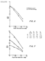
- the beam currents as presented in figures 6 and 7 were obtained by using the approximation of equation (9) and integrating the corrected current density over an angle a from zero to ninety degrees.
- Cathode lifetime tests were conducted with argon. Using tungsten cathodes with a diameter of 0.50mm (0.020 inch), lifetimes of twenty to twenty- two hours were obtained at an anode current of five amperes which corresponded to an ion beam current of about one ampere. Lifetime tests were also conducted with oxygen, again using the same type of tungsten cathode. With oxygen, lifetimes at an anode current of five amperes range from nine to fourteen hours.
- any other reactive gas employed for plasma production it is to be noted that the hollow-cathode gas flow was introduced at a considerable distance from the main discharge within anode 24. Accordingly, only a fraction of the inert gas would return to the discharge region to be ionized.
- the components considered as possibly subject to erosion are the cathode 22, distributor 42 and anode 24.
- the impurity ratios for those three components were, respectively, ⁇ 4 ⁇ 10- 4 with a tungsten cathode, ⁇ 13 ⁇ 10- 4 for a carbon distributor and -0 for a carbon anode.
- oxygen the ratios were ⁇ 17 ⁇ 10- 4 for a tungsten cathode ⁇ 3 ⁇ 10- 4 for a stainless steel distributor and ⁇ 2 ⁇ 10- 4 for a stainless steel anode.
- a hollow cathode could eliminate the cathode as a contamination source. This would leave only the smaller contributions of the distributor and the anode.
- other materials may be used in the alternative for construction of either the distributor or the anode. In any event, contamination is generally low, making the source suited for many applications.
- One result of that increased ratio is the creation of a potential gradient in the plasma which tends to direct the ions outward from source 20 into a beam. Through the effect on the potential distribution and, therefore, on the ions, that effect is used to direct the ions in the desired direction. This reduces the effect of erosion which would be caused by ions moving in the opposite direction and striking interior portions of source 20.
- permeable material is used to shape and control the magnetic field. That is, it is a ferromagnetic material that exhibits a relative permeability (with reference to a vacuum) that is substantially greater than unity and preferably at least one or two orders of magnitude greater.
- Distributer 42 is located behind the anode (opposite the direction of the cathode 22.) Ion source 20 has been operated with that distributor at ground potential, typically the vacuum chamber potential, and to which ground the center tap of the cathode is attached. In normal operation, ground is usually within several volts of the potential of the ion beam. With that manner of operation, it was found that the distributor could be struck by energetic ions in the discharge region, so that sputtering due to those collisions could become a major source of sputter contamination from source 20 itself.
- distributor 42 electrically isolating distributor 42.
- distributor - 42 electrically floats at a positive potential. This reduces the energy of the positive ions striking it and probably also reduces the number of ions which may strike it.
- others of the conductive elements within the established magnetic field may be electrically isolated from the anode and the cathode, thereby being allowed to float electrically. That also may include additional field shaping elements located between the anode and the cathode.
- gas distribution is controlled so that most of the gas flow passes through anode 24. Because the electrons can cross the magnetic field easier by going downstream, crossing and then returning to the anode, increased plasma density downstream of the anode provides a lower impedance path and reduces the operating voltage necessary. Plasma density in a region can be controlled by controlling the gas flow to that region. Thus, the gas distribution may be used to control the operating voltage.
- source 20 and all essential elements, except cathode 22, are circular or annular in shape. Accordingly, the ion beam produced exhibits a circular cross-section across its width or diameter. This ordinarily is suitable for most bombardment uses.
- a beam pattern which is elliptical or even rectangular.
- a narrow but wide beam pattern may be more suitable. That is accomplished by changing the shape of anode 24 to be elliptical or rectangular rather than annular as specifically illustrated in figure 1.
Landscapes
- Chemical & Material Sciences (AREA)
- Engineering & Computer Science (AREA)
- Combustion & Propulsion (AREA)
- Electron Sources, Ion Sources (AREA)
Applications Claiming Priority (2)
| Application Number | Priority Date | Filing Date | Title |
|---|---|---|---|
| US06/920,798 US4862032A (en) | 1986-10-20 | 1986-10-20 | End-Hall ion source |
| US920798 | 1986-10-20 |
Publications (2)
| Publication Number | Publication Date |
|---|---|
| EP0265365A1 true EP0265365A1 (de) | 1988-04-27 |
| EP0265365B1 EP0265365B1 (de) | 1993-01-07 |
Family
ID=25444422
Family Applications (1)
| Application Number | Title | Priority Date | Filing Date |
|---|---|---|---|
| EP87630203A Expired - Lifetime EP0265365B1 (de) | 1986-10-20 | 1987-10-15 | End-Hall-Ionenquelle |
Country Status (4)
| Country | Link |
|---|---|
| US (1) | US4862032A (de) |
| EP (1) | EP0265365B1 (de) |
| JP (1) | JPS63108646A (de) |
| DE (1) | DE3783432T2 (de) |
Cited By (9)
| Publication number | Priority date | Publication date | Assignee | Title |
|---|---|---|---|---|
| EP0781921A1 (de) * | 1995-12-29 | 1997-07-02 | Societe Europeenne De Propulsion | Ionenquelle mit geschlossener Elektronendrift |
| EP0800197A1 (de) * | 1996-04-01 | 1997-10-08 | Matra Marconi Space France S.A. | Halleffekt-Plasmabeschleuniger |
| WO1999022396A3 (en) * | 1997-10-24 | 1999-09-10 | Filplas Vacuum Technology Pte | Enhanced macroparticle filter and cathode arc source |
| WO2002037521A3 (en) * | 2000-11-03 | 2003-03-13 | Tokyo Electron Ltd | Hall effect ion source at high current density |
| WO2005008066A1 (en) * | 2003-06-17 | 2005-01-27 | Kaufman & Robinson, Inc. | Modular gridless ion source |
| FR2859487A1 (fr) * | 2003-09-04 | 2005-03-11 | Essilor Int | Procede de depot d'une couche amorphe contenant majoritairement du fluor et du carbone et dispositif convenant a sa mise en oeuvre |
| US7014738B2 (en) | 1997-10-24 | 2006-03-21 | Filplas Vacuum Technology Pte Ltd. | Enhanced macroparticle filter and cathode arc source |
| US7511271B2 (en) | 2005-02-18 | 2009-03-31 | Hitachi Science Systems, Ltd. | Scanning electron microscope |
| EP1390964A4 (de) * | 2001-04-20 | 2009-12-30 | Applied Process Technologies | Dipol-ionenquelle |
Families Citing this family (112)
| Publication number | Priority date | Publication date | Assignee | Title |
|---|---|---|---|---|
| US5225057A (en) * | 1988-02-08 | 1993-07-06 | Optical Coating Laboratory, Inc. | Process for depositing optical films on both planar and non-planar substrates |
| US5618388A (en) * | 1988-02-08 | 1997-04-08 | Optical Coating Laboratory, Inc. | Geometries and configurations for magnetron sputtering apparatus |
| US5798027A (en) * | 1988-02-08 | 1998-08-25 | Optical Coating Laboratory, Inc. | Process for depositing optical thin films on both planar and non-planar substrates |
| US4950957A (en) * | 1988-11-04 | 1990-08-21 | Westinghouse Electric Corp. | Extended ion sources and method for using them in an insulation defect detector |
| EP0463408A3 (en) * | 1990-06-22 | 1992-07-08 | Hauzer Techno Coating Europe Bv | Plasma accelerator with closed electron drift |
| US5455081A (en) * | 1990-09-25 | 1995-10-03 | Nippon Steel Corporation | Process for coating diamond-like carbon film and coated thin strip |
| GB9127433D0 (en) * | 1991-12-27 | 1992-02-19 | Matra Marconi Space Uk | Propulsion system for spacecraft |
| FR2693770B1 (fr) * | 1992-07-15 | 1994-10-14 | Europ Propulsion | Moteur à plasma à dérive fermée d'électrons. |
| US5616179A (en) * | 1993-12-21 | 1997-04-01 | Commonwealth Scientific Corporation | Process for deposition of diamondlike, electrically conductive and electron-emissive carbon-based films |
| US5888593A (en) * | 1994-03-03 | 1999-03-30 | Monsanto Company | Ion beam process for deposition of highly wear-resistant optical coatings |
| US5508368A (en) * | 1994-03-03 | 1996-04-16 | Diamonex, Incorporated | Ion beam process for deposition of highly abrasion-resistant coatings |
| US5846649A (en) * | 1994-03-03 | 1998-12-08 | Monsanto Company | Highly durable and abrasion-resistant dielectric coatings for lenses |
| US5618619A (en) * | 1994-03-03 | 1997-04-08 | Monsanto Company | Highly abrasion-resistant, flexible coatings for soft substrates |
| US5523646A (en) * | 1994-08-17 | 1996-06-04 | Tucciarone; John F. | An arc chamber assembly for use in an ionization source |
| US5576600A (en) * | 1994-12-23 | 1996-11-19 | Dynatenn, Inc. | Broad high current ion source |
| US5763989A (en) * | 1995-03-16 | 1998-06-09 | Front Range Fakel, Inc. | Closed drift ion source with improved magnetic field |
| DE59602769D1 (de) * | 1995-05-16 | 1999-09-23 | Dresden Vakuumtech Gmbh | Ionenquelle |
| DE19531141C2 (de) * | 1995-05-16 | 1997-03-27 | Dresden Vakuumtech Gmbh | Ionenquelle |
| RU2084085C1 (ru) * | 1995-07-14 | 1997-07-10 | Центральный научно-исследовательский институт машиностроения | Ускоритель с замкнутым дрейфом электронов |
| US5793195A (en) * | 1995-08-30 | 1998-08-11 | Kaufman & Robinson, Inc. | Angular distribution probe |
| EP0778415B1 (de) * | 1995-12-09 | 2007-10-17 | Matra Marconi Space France S.A. | Steuerbarer Hall-Effekt-Antrieb |
| IL126413A0 (en) * | 1996-04-01 | 1999-05-09 | Int Scient Products | A hall effect plasma accelerator |
| CA2250917A1 (en) * | 1996-04-01 | 1997-10-09 | International Scientific Products | A hall effect plasma thruster |
| EP0827179B1 (de) * | 1996-08-30 | 2001-11-28 | Varian, Inc. | Einfach-Potential Ionenquelle |
| US5855745A (en) * | 1997-04-23 | 1999-01-05 | Sierra Applied Sciences, Inc. | Plasma processing system utilizing combined anode/ ion source |
| US6086962A (en) | 1997-07-25 | 2000-07-11 | Diamonex, Incorporated | Method for deposition of diamond-like carbon and silicon-doped diamond-like carbon coatings from a hall-current ion source |
| US5973447A (en) * | 1997-07-25 | 1999-10-26 | Monsanto Company | Gridless ion source for the vacuum processing of materials |
| US6271529B1 (en) | 1997-12-01 | 2001-08-07 | Ebara Corporation | Ion implantation with charge neutralization |
| WO1999028624A1 (en) * | 1997-12-04 | 1999-06-10 | Primex Technologies, Inc. | Cathode current sharing apparatus and method therefor |
| US6368678B1 (en) | 1998-05-13 | 2002-04-09 | Terry Bluck | Plasma processing system and method |
| US6215124B1 (en) | 1998-06-05 | 2001-04-10 | Primex Aerospace Company | Multistage ion accelerators with closed electron drift |
| US6612105B1 (en) | 1998-06-05 | 2003-09-02 | Aerojet-General Corporation | Uniform gas distribution in ion accelerators with closed electron drift |
| US6208080B1 (en) | 1998-06-05 | 2001-03-27 | Primex Aerospace Company | Magnetic flux shaping in ion accelerators with closed electron drift |
| AUPP479298A0 (en) | 1998-07-21 | 1998-08-13 | Sainty, Wayne | Ion source |
| US6392244B1 (en) | 1998-09-25 | 2002-05-21 | Seagate Technology Llc | Ion beam deposition of diamond-like carbon overcoats by hydrocarbon source gas pulsing |
| US6518693B1 (en) | 1998-11-13 | 2003-02-11 | Aerojet-General Corporation | Method and apparatus for magnetic voltage isolation |
| US6449941B1 (en) * | 1999-04-28 | 2002-09-17 | Lockheed Martin Corporation | Hall effect electric propulsion system |
| US6733590B1 (en) * | 1999-05-03 | 2004-05-11 | Seagate Technology Llc. | Method and apparatus for multilayer deposition utilizing a common beam source |
| US6259102B1 (en) * | 1999-05-20 | 2001-07-10 | Evgeny V. Shun'ko | Direct current gas-discharge ion-beam source with quadrupole magnetic separating system |
| US6870164B1 (en) * | 1999-10-15 | 2005-03-22 | Kaufman & Robinson, Inc. | Pulsed operation of hall-current ion sources |
| WO2001053564A1 (en) * | 2000-01-21 | 2001-07-26 | Advanced Energy Industries, Inc. | Method and apparatus for neutralization of ion beam using ac or dc ion source |
| WO2001073883A2 (en) * | 2000-03-24 | 2001-10-04 | Cymbet Corporation | Low-temperature fabrication of thin-film energy-storage devices |
| US6710524B2 (en) | 2000-04-11 | 2004-03-23 | Satis Vacuum Industries Vertrieb Ag | Plasma source |
| US6849854B2 (en) * | 2001-01-18 | 2005-02-01 | Saintech Pty Ltd. | Ion source |
| US6456011B1 (en) * | 2001-02-23 | 2002-09-24 | Front Range Fakel, Inc. | Magnetic field for small closed-drift ion source |
| US6488821B2 (en) | 2001-03-16 | 2002-12-03 | 4 Wave Inc. | System and method for performing sputter deposition using a divergent ion beam source and a rotating substrate |
| US6444945B1 (en) | 2001-03-28 | 2002-09-03 | Cp Films, Inc. | Bipolar plasma source, plasma sheet source, and effusion cell utilizing a bipolar plasma source |
| US7023128B2 (en) * | 2001-04-20 | 2006-04-04 | Applied Process Technologies, Inc. | Dipole ion source |
| US6750600B2 (en) * | 2001-05-03 | 2004-06-15 | Kaufman & Robinson, Inc. | Hall-current ion source |
| RU2208871C1 (ru) * | 2002-03-26 | 2003-07-20 | Минаков Валерий Иванович | Плазменный источник электронов |
| US6724160B2 (en) * | 2002-04-12 | 2004-04-20 | Kaufman & Robinson, Inc. | Ion-source neutralization with a hot-filament cathode-neutralizer |
| US6608431B1 (en) | 2002-05-24 | 2003-08-19 | Kaufman & Robinson, Inc. | Modular gridless ion source |
| WO2004003954A1 (en) * | 2002-06-27 | 2004-01-08 | Kaufman & Robinson, Inc. | Industrial hollow cathode |
| US7667379B2 (en) * | 2002-06-27 | 2010-02-23 | Kaufman & Robinson, Inc. | Industrial hollow cathode with radiation shield structure |
| US7294209B2 (en) | 2003-01-02 | 2007-11-13 | Cymbet Corporation | Apparatus and method for depositing material onto a substrate using a roll-to-roll mask |
| US6906436B2 (en) * | 2003-01-02 | 2005-06-14 | Cymbet Corporation | Solid state activity-activated battery device and method |
| US7603144B2 (en) | 2003-01-02 | 2009-10-13 | Cymbet Corporation | Active wireless tagging system on peel and stick substrate |
| US20040131760A1 (en) * | 2003-01-02 | 2004-07-08 | Stuart Shakespeare | Apparatus and method for depositing material onto multiple independently moving substrates in a chamber |
| US7300166B2 (en) * | 2003-03-05 | 2007-11-27 | Electrochromix, Inc. | Electrochromic mirrors and other electrooptic devices |
| DE10318566B4 (de) * | 2003-04-15 | 2005-11-17 | Fresnel Optics Gmbh | Verfahren und Werkzeug zur Herstellung transparenter optischer Elemente aus polymeren Werkstoffen |
| US6963162B1 (en) | 2003-06-12 | 2005-11-08 | Dontech Inc. | Gas distributor for an ion source |
| WO2005038849A1 (en) * | 2003-10-15 | 2005-04-28 | Saintech Pty Ltd | Ion source with modified gas delivery |
| US7211351B2 (en) * | 2003-10-16 | 2007-05-01 | Cymbet Corporation | Lithium/air batteries with LiPON as separator and protective barrier and method |
| US7498586B2 (en) * | 2003-10-31 | 2009-03-03 | Saintech Pty, Ltd. | Ion source control system |
| US7030576B2 (en) * | 2003-12-02 | 2006-04-18 | United Technologies Corporation | Multichannel hall effect thruster |
| US7098667B2 (en) * | 2003-12-31 | 2006-08-29 | Fei Company | Cold cathode ion gauge |
| CN1957487A (zh) | 2004-01-06 | 2007-05-02 | Cymbet公司 | 具有一个或者更多个可限定层的层式阻挡物结构和方法 |
| US7342236B2 (en) * | 2004-02-23 | 2008-03-11 | Veeco Instruments, Inc. | Fluid-cooled ion source |
| US7116054B2 (en) * | 2004-04-23 | 2006-10-03 | Viacheslav V. Zhurin | High-efficient ion source with improved magnetic field |
| US7617092B2 (en) * | 2004-12-01 | 2009-11-10 | Microsoft Corporation | Safe, secure resource editing for application localization |
| CN100463099C (zh) * | 2004-12-08 | 2009-02-18 | 鸿富锦精密工业(深圳)有限公司 | 离子源 |
| US7509795B2 (en) * | 2005-01-13 | 2009-03-31 | Lockheed-Martin Corporation | Systems and methods for plasma propulsion |
| US7624566B1 (en) | 2005-01-18 | 2009-12-01 | The United States Of America As Represented By The Administrator Of National Aeronautics And Space Administration | Magnetic circuit for hall effect plasma accelerator |
| US7500350B1 (en) | 2005-01-28 | 2009-03-10 | The United States Of America As Represented By The Administrator Of The National Aeronautics And Space Administration | Elimination of lifetime limiting mechanism of hall thrusters |
| US7476869B2 (en) * | 2005-02-18 | 2009-01-13 | Veeco Instruments, Inc. | Gas distributor for ion source |
| US7425711B2 (en) * | 2005-02-18 | 2008-09-16 | Veeco Instruments, Inc. | Thermal control plate for ion source |
| US7439521B2 (en) * | 2005-02-18 | 2008-10-21 | Veeco Instruments, Inc. | Ion source with removable anode assembly |
| US7566883B2 (en) * | 2005-02-18 | 2009-07-28 | Veeco Instruments, Inc. | Thermal transfer sheet for ion source |
| JP2009502011A (ja) | 2005-07-15 | 2009-01-22 | シンベット・コーポレイション | 軟質および硬質電解質層付き薄膜電池および方法 |
| US7776478B2 (en) | 2005-07-15 | 2010-08-17 | Cymbet Corporation | Thin-film batteries with polymer and LiPON electrolyte layers and method |
| US7728498B2 (en) * | 2006-03-25 | 2010-06-01 | Kaufman & Robinson, Inc. | Industrial hollow cathode |
| US7312579B2 (en) * | 2006-04-18 | 2007-12-25 | Colorado Advanced Technology Llc | Hall-current ion source for ion beams of low and high energy for technological applications |
| EP2092544A2 (de) * | 2006-10-19 | 2009-08-26 | Applied Process Technologies, Inc. | Ionenquelle mit geschlossener streuung |
| US9447779B2 (en) | 2006-11-09 | 2016-09-20 | Alexander Kapulkin | Low-power hall thruster |
| US7853364B2 (en) * | 2006-11-30 | 2010-12-14 | Veeco Instruments, Inc. | Adaptive controller for ion source |
| US7589474B2 (en) * | 2006-12-06 | 2009-09-15 | City University Of Hong Kong | Ion source with upstream inner magnetic pole piece |
| WO2008106448A2 (en) * | 2007-02-26 | 2008-09-04 | Veeco Instruments Inc. | Ion sources and methods of operating an electromagnet of an ion source |
| US7800083B2 (en) * | 2007-11-06 | 2010-09-21 | Axcelis Technologies, Inc. | Plasma electron flood for ion beam implanter |
| US7863582B2 (en) * | 2008-01-25 | 2011-01-04 | Valery Godyak | Ion-beam source |
| WO2009106208A1 (en) | 2008-02-29 | 2009-09-03 | Merck Patent Gmbh | Alignment film for liquid crystals obtainable by direct particle beam deposition |
| EP2368257A4 (de) * | 2008-12-08 | 2016-03-09 | Gen Plasma Inc | Magnetfeld-ionenquellenvorrichtung mit geschlossener drift und selbstreinigender anode und verfahren zur substratmodifizierung damit |
| FR2950115B1 (fr) * | 2009-09-17 | 2012-11-16 | Snecma | Propulseur plasmique a effet hall |
| US8698401B2 (en) * | 2010-01-05 | 2014-04-15 | Kaufman & Robinson, Inc. | Mitigation of plasma-inductor termination |
| US8508134B2 (en) | 2010-07-29 | 2013-08-13 | Evgeny Vitalievich Klyuev | Hall-current ion source with improved ion beam energy distribution |
| US9853325B2 (en) | 2011-06-29 | 2017-12-26 | Space Charge, LLC | Rugged, gel-free, lithium-free, high energy density solid-state electrochemical energy storage devices |
| US11996517B2 (en) | 2011-06-29 | 2024-05-28 | Space Charge, LLC | Electrochemical energy storage devices |
| US11527774B2 (en) | 2011-06-29 | 2022-12-13 | Space Charge, LLC | Electrochemical energy storage devices |
| US10601074B2 (en) | 2011-06-29 | 2020-03-24 | Space Charge, LLC | Rugged, gel-free, lithium-free, high energy density solid-state electrochemical energy storage devices |
| US10658705B2 (en) | 2018-03-07 | 2020-05-19 | Space Charge, LLC | Thin-film solid-state energy storage devices |
| GB201210994D0 (en) | 2012-06-21 | 2012-08-01 | Univ Surrey | Ion accelerators |
| US9347127B2 (en) * | 2012-07-16 | 2016-05-24 | Veeco Instruments, Inc. | Film deposition assisted by angular selective etch on a surface |
| US8994258B1 (en) | 2013-09-25 | 2015-03-31 | Kaufman & Robinson, Inc. | End-hall ion source with enhanced radiation cooling |
| US10273944B1 (en) | 2013-11-08 | 2019-04-30 | The United States Of America As Represented By The Administrator Of National Aeronautics And Space Administration | Propellant distributor for a thruster |
| JP6180952B2 (ja) | 2014-01-31 | 2017-08-16 | 東芝メモリ株式会社 | デバイス製造装置及び磁気デバイスの製造方法 |
| JP6318447B2 (ja) * | 2014-05-23 | 2018-05-09 | 三菱重工業株式会社 | プラズマ加速装置及びプラズマ加速方法 |
| CN104362065B (zh) * | 2014-10-23 | 2017-02-15 | 中国电子科技集团公司第四十八研究所 | 一种用于离子束刻蚀机的大口径平行束离子源 |
| RU2648268C1 (ru) * | 2016-12-14 | 2018-03-23 | федеральное государственное бюджетное образовательное учреждение высшего образования "Санкт-Петербургский горный университет" | Способ определения параметров нейтральной и электронной компонент неравновесной плазмы |
| WO2018118223A1 (en) | 2016-12-21 | 2018-06-28 | Phase Four, Inc. | Plasma production and control device |
| US20190107103A1 (en) | 2017-10-09 | 2019-04-11 | Phase Four, Inc. | Electrothermal radio frequency thruster and components |
| US10636645B2 (en) * | 2018-04-20 | 2020-04-28 | Perkinelmer Health Sciences Canada, Inc. | Dual chamber electron impact and chemical ionization source |
| US12195205B2 (en) | 2019-09-04 | 2025-01-14 | Phase Four, Inc. | Propellant injector system for plasma production devices and thrusters |
| CN113993261B (zh) * | 2021-09-15 | 2023-03-21 | 西安交通大学 | 磁增强型等离子体桥电子源 |
Citations (6)
| Publication number | Priority date | Publication date | Assignee | Title |
|---|---|---|---|---|
| GB1543530A (en) * | 1977-03-18 | 1979-04-04 | Dmitriev J | Ion source |
| DE2904049A1 (de) * | 1978-02-03 | 1979-08-09 | Thomson Csf | Ionenquelle |
| DE2913464A1 (de) * | 1979-04-04 | 1980-10-16 | Deutsche Forsch Luft Raumfahrt | Gleichstrom-plasmabrenner |
| GB2076587A (en) * | 1980-05-02 | 1981-12-02 | Telephone Public Corp | Plasma deposition apparatus |
| EP0095879A2 (de) * | 1982-06-01 | 1983-12-07 | International Business Machines Corporation | Verfahren und Vorrichtung zur Oberflächenbehandlung mit einem Niederenergie- und Hochintensitätsionenbündel |
| EP0174058A2 (de) * | 1984-08-31 | 1986-03-12 | Kyoto University | Hall-Beschleuniger mit Vorionisationsentladung |
Family Cites Families (10)
| Publication number | Priority date | Publication date | Assignee | Title |
|---|---|---|---|---|
| US3309873A (en) * | 1964-08-31 | 1967-03-21 | Electro Optical Systems Inc | Plasma accelerator using hall currents |
| US3388291A (en) * | 1964-08-31 | 1968-06-11 | Electro Optical Systems Inc | Annular magnetic hall current accelerator |
| US3360682A (en) * | 1965-10-15 | 1967-12-26 | Giannini Scient Corp | Apparatus and method for generating high-enthalpy plasma under high-pressure conditions |
| US3735591A (en) * | 1971-08-30 | 1973-05-29 | Usa | Magneto-plasma-dynamic arc thruster |
| US3956666A (en) * | 1975-01-27 | 1976-05-11 | Ion Tech, Inc. | Electron-bombardment ion sources |
| DE2633778C3 (de) * | 1976-07-28 | 1981-12-24 | Messerschmitt-Bölkow-Blohm GmbH, 8000 München | Ionentriebwerk |
| JPS5562734A (en) * | 1978-11-01 | 1980-05-12 | Toshiba Corp | Ion source and ion etching method |
| US4361472A (en) * | 1980-09-15 | 1982-11-30 | Vac-Tec Systems, Inc. | Sputtering method and apparatus utilizing improved ion source |
| US4548033A (en) * | 1983-06-22 | 1985-10-22 | Cann Gordon L | Spacecraft optimized arc rocket |
| US4684848A (en) * | 1983-09-26 | 1987-08-04 | Kaufman & Robinson, Inc. | Broad-beam electron source |
-
1986
- 1986-10-20 US US06/920,798 patent/US4862032A/en not_active Expired - Lifetime
-
1987
- 1987-07-06 JP JP62168495A patent/JPS63108646A/ja active Granted
- 1987-10-15 EP EP87630203A patent/EP0265365B1/de not_active Expired - Lifetime
- 1987-10-15 DE DE8787630203T patent/DE3783432T2/de not_active Expired - Lifetime
Patent Citations (6)
| Publication number | Priority date | Publication date | Assignee | Title |
|---|---|---|---|---|
| GB1543530A (en) * | 1977-03-18 | 1979-04-04 | Dmitriev J | Ion source |
| DE2904049A1 (de) * | 1978-02-03 | 1979-08-09 | Thomson Csf | Ionenquelle |
| DE2913464A1 (de) * | 1979-04-04 | 1980-10-16 | Deutsche Forsch Luft Raumfahrt | Gleichstrom-plasmabrenner |
| GB2076587A (en) * | 1980-05-02 | 1981-12-02 | Telephone Public Corp | Plasma deposition apparatus |
| EP0095879A2 (de) * | 1982-06-01 | 1983-12-07 | International Business Machines Corporation | Verfahren und Vorrichtung zur Oberflächenbehandlung mit einem Niederenergie- und Hochintensitätsionenbündel |
| EP0174058A2 (de) * | 1984-08-31 | 1986-03-12 | Kyoto University | Hall-Beschleuniger mit Vorionisationsentladung |
Non-Patent Citations (1)
| Title |
|---|
| J.L. VOSSEN "Thin Film Processes", Part II-5, "Ion Beam Deposition", 1978 Academic Press, Inc., New York pages 176-181 * page 179, line 29 - page 181, line 6; fig. 4 * * |
Cited By (19)
| Publication number | Priority date | Publication date | Assignee | Title |
|---|---|---|---|---|
| FR2743191A1 (fr) * | 1995-12-29 | 1997-07-04 | Europ Propulsion | Source d'ions a derive fermee d'electrons |
| US5945781A (en) * | 1995-12-29 | 1999-08-31 | Societe Nationale D'etude Et De Construction De Moteurs D'aviation | Ion source with closed electron drift |
| EP0781921A1 (de) * | 1995-12-29 | 1997-07-02 | Societe Europeenne De Propulsion | Ionenquelle mit geschlossener Elektronendrift |
| EP0800197A1 (de) * | 1996-04-01 | 1997-10-08 | Matra Marconi Space France S.A. | Halleffekt-Plasmabeschleuniger |
| US7014738B2 (en) | 1997-10-24 | 2006-03-21 | Filplas Vacuum Technology Pte Ltd. | Enhanced macroparticle filter and cathode arc source |
| WO1999022396A3 (en) * | 1997-10-24 | 1999-09-10 | Filplas Vacuum Technology Pte | Enhanced macroparticle filter and cathode arc source |
| GB2347148A (en) * | 1997-10-24 | 2000-08-30 | Filplas Vacuum Technology Pte | Enhanced macroparticle filter and cathode arc source |
| GB2347148B (en) * | 1997-10-24 | 2002-11-13 | Filplas Vacuum Technology Pte | Enhanced macroparticle filter and cathode arc source |
| US6511585B1 (en) | 1997-10-24 | 2003-01-28 | Filplas Vacuum Technology Pte Ltd. | Enhanced macroparticle filter and cathode arc source |
| WO2002037521A3 (en) * | 2000-11-03 | 2003-03-13 | Tokyo Electron Ltd | Hall effect ion source at high current density |
| US6819053B2 (en) | 2000-11-03 | 2004-11-16 | Tokyo Electron Limited | Hall effect ion source at high current density |
| EP1390964A4 (de) * | 2001-04-20 | 2009-12-30 | Applied Process Technologies | Dipol-ionenquelle |
| WO2005008066A1 (en) * | 2003-06-17 | 2005-01-27 | Kaufman & Robinson, Inc. | Modular gridless ion source |
| FR2859487A1 (fr) * | 2003-09-04 | 2005-03-11 | Essilor Int | Procede de depot d'une couche amorphe contenant majoritairement du fluor et du carbone et dispositif convenant a sa mise en oeuvre |
| WO2005024086A1 (fr) * | 2003-09-04 | 2005-03-17 | Essilor International | Procede de depot d’une couche amorphe contenant majoritairement du fluor et du carbone et dispositif convenant a sa mise en oeuvre |
| JP2007504360A (ja) * | 2003-09-04 | 2007-03-01 | エシロール アンテルナショナル コムパニー ジェネラル ドプテイク | フッ素及び炭素を専ら含有する非結晶層を付着させるための方法及びこれを実施するための装置 |
| JP4772680B2 (ja) * | 2003-09-04 | 2011-09-14 | エシロール アンテルナショナル コムパニー ジェネラル ドプテイク | フッ素及び炭素を専ら含有する非結晶層を付着させるための方法及びこれを実施するための装置 |
| US20160024643A1 (en) * | 2003-09-04 | 2016-01-28 | Essilor International (Compagnie Generale D'optique) | Method for depositing an amorphous layer primarily containing fluorine and carbon, and device suited for carrying out this method |
| US7511271B2 (en) | 2005-02-18 | 2009-03-31 | Hitachi Science Systems, Ltd. | Scanning electron microscope |
Also Published As
| Publication number | Publication date |
|---|---|
| US4862032A (en) | 1989-08-29 |
| DE3783432D1 (de) | 1993-02-18 |
| DE3783432T2 (de) | 1993-05-06 |
| JPH0578133B2 (de) | 1993-10-28 |
| JPS63108646A (ja) | 1988-05-13 |
| EP0265365B1 (de) | 1993-01-07 |
Similar Documents
| Publication | Publication Date | Title |
|---|---|---|
| EP0265365B1 (de) | End-Hall-Ionenquelle | |
| US5646476A (en) | Channel ion source | |
| EP0462165B1 (de) | Ionenstrahlkanone | |
| US4486665A (en) | Negative ion source | |
| Kaufman et al. | End‐Hall ion source | |
| US7116054B2 (en) | High-efficient ion source with improved magnetic field | |
| RU2092983C1 (ru) | Плазменный ускоритель | |
| EP0505327B1 (de) | Elektronzyklotronresonanz-Ionentriebwerk | |
| US20020145389A1 (en) | Magnetic field for small closed-drift ion source | |
| US6224725B1 (en) | Unbalanced magnetron sputtering with auxiliary cathode | |
| US4559477A (en) | Three chamber negative ion source | |
| US6294862B1 (en) | Multi-cusp ion source | |
| Belov et al. | Pulsed high-intensity source of polarized protons | |
| EP0480688A2 (de) | Plasmaquellenvorrichtung für Ionenimplantierung | |
| EP0094473B1 (de) | Verfahren und Vorrichtung zur Erzeugung eines Ionenstrahles | |
| US20090159441A1 (en) | Plasma Film Deposition System | |
| US6740212B2 (en) | Rectangular magnetron sputtering cathode with high target utilization | |
| US6242749B1 (en) | Ion-beam source with uniform distribution of ion-current density on the surface of an object being treated | |
| CA1268864A (en) | End-hall ion source | |
| Takao et al. | Development of small-scale microwave discharge ion thruster | |
| Papernyi et al. | Separation of the heavy and light ion components in a plasma flow propagating in a curvilinear magnetic field | |
| Kotov | Broad beam low-energy ion source for ion-beam assisted deposition and material processing | |
| Taylor et al. | Atomic Energy of Canada Limited | |
| Rawat et al. | Effects of axial magnetic field in a magnetic multipole line cusp ion source | |
| Sanchez et al. | Extraction characteristics of ions in a magnetized sheet plasma |
Legal Events
| Date | Code | Title | Description |
|---|---|---|---|
| PUAI | Public reference made under article 153(3) epc to a published international application that has entered the european phase |
Free format text: ORIGINAL CODE: 0009012 |
|
| AK | Designated contracting states |
Kind code of ref document: A1 Designated state(s): CH DE FR GB LI NL |
|
| 17P | Request for examination filed |
Effective date: 19881020 |
|
| 17Q | First examination report despatched |
Effective date: 19890720 |
|
| GRAA | (expected) grant |
Free format text: ORIGINAL CODE: 0009210 |
|
| AK | Designated contracting states |
Kind code of ref document: B1 Designated state(s): CH DE FR GB LI NL |
|
| ET | Fr: translation filed | ||
| REF | Corresponds to: |
Ref document number: 3783432 Country of ref document: DE Date of ref document: 19930218 |
|
| PLBE | No opposition filed within time limit |
Free format text: ORIGINAL CODE: 0009261 |
|
| STAA | Information on the status of an ep patent application or granted ep patent |
Free format text: STATUS: NO OPPOSITION FILED WITHIN TIME LIMIT |
|
| 26N | No opposition filed | ||
| REG | Reference to a national code |
Ref country code: GB Ref legal event code: IF02 |
|
| PGFP | Annual fee paid to national office [announced via postgrant information from national office to epo] |
Ref country code: CH Payment date: 20061012 Year of fee payment: 20 |
|
| PGFP | Annual fee paid to national office [announced via postgrant information from national office to epo] |
Ref country code: NL Payment date: 20061016 Year of fee payment: 20 |
|
| PGFP | Annual fee paid to national office [announced via postgrant information from national office to epo] |
Ref country code: DE Payment date: 20061023 Year of fee payment: 20 Ref country code: GB Payment date: 20061023 Year of fee payment: 20 |
|
| REG | Reference to a national code |
Ref country code: GB Ref legal event code: PE20 |
|
| REG | Reference to a national code |
Ref country code: CH Ref legal event code: PL |
|
| NLV7 | Nl: ceased due to reaching the maximum lifetime of a patent |
Effective date: 20071015 |
|
| PG25 | Lapsed in a contracting state [announced via postgrant information from national office to epo] |
Ref country code: NL Free format text: LAPSE BECAUSE OF EXPIRATION OF PROTECTION Effective date: 20071015 |
|
| PG25 | Lapsed in a contracting state [announced via postgrant information from national office to epo] |
Ref country code: GB Free format text: LAPSE BECAUSE OF EXPIRATION OF PROTECTION Effective date: 20071014 |
|
| PGFP | Annual fee paid to national office [announced via postgrant information from national office to epo] |
Ref country code: FR Payment date: 20061016 Year of fee payment: 20 |