EP0265368A1 - Rückspülfilter und Druckregler dazu - Google Patents
Rückspülfilter und Druckregler dazu Download PDFInfo
- Publication number
- EP0265368A1 EP0265368A1 EP87630208A EP87630208A EP0265368A1 EP 0265368 A1 EP0265368 A1 EP 0265368A1 EP 87630208 A EP87630208 A EP 87630208A EP 87630208 A EP87630208 A EP 87630208A EP 0265368 A1 EP0265368 A1 EP 0265368A1
- Authority
- EP
- European Patent Office
- Prior art keywords
- housing
- central tube
- filter
- filter body
- inlet
- Prior art date
- Legal status (The legal status is an assumption and is not a legal conclusion. Google has not performed a legal analysis and makes no representation as to the accuracy of the status listed.)
- Granted
Links
Images

Classifications
-
- B—PERFORMING OPERATIONS; TRANSPORTING
- B01—PHYSICAL OR CHEMICAL PROCESSES OR APPARATUS IN GENERAL
- B01D—SEPARATION
- B01D29/00—Filters with filtering elements stationary during filtration, e.g. pressure or suction filters, not covered by groups B01D24/00 - B01D27/00; Filtering elements therefor
- B01D29/11—Filters with filtering elements stationary during filtration, e.g. pressure or suction filters, not covered by groups B01D24/00 - B01D27/00; Filtering elements therefor with bag, cage, hose, tube, sleeve or like filtering elements
- B01D29/114—Filters with filtering elements stationary during filtration, e.g. pressure or suction filters, not covered by groups B01D24/00 - B01D27/00; Filtering elements therefor with bag, cage, hose, tube, sleeve or like filtering elements arranged for inward flow filtration
-
- B—PERFORMING OPERATIONS; TRANSPORTING
- B01—PHYSICAL OR CHEMICAL PROCESSES OR APPARATUS IN GENERAL
- B01D—SEPARATION
- B01D29/00—Filters with filtering elements stationary during filtration, e.g. pressure or suction filters, not covered by groups B01D24/00 - B01D27/00; Filtering elements therefor
- B01D29/50—Filters with filtering elements stationary during filtration, e.g. pressure or suction filters, not covered by groups B01D24/00 - B01D27/00; Filtering elements therefor with multiple filtering elements, characterised by their mutual disposition
- B01D29/52—Filters with filtering elements stationary during filtration, e.g. pressure or suction filters, not covered by groups B01D24/00 - B01D27/00; Filtering elements therefor with multiple filtering elements, characterised by their mutual disposition in parallel connection
- B01D29/54—Filters with filtering elements stationary during filtration, e.g. pressure or suction filters, not covered by groups B01D24/00 - B01D27/00; Filtering elements therefor with multiple filtering elements, characterised by their mutual disposition in parallel connection arranged concentrically or coaxially
-
- B—PERFORMING OPERATIONS; TRANSPORTING
- B01—PHYSICAL OR CHEMICAL PROCESSES OR APPARATUS IN GENERAL
- B01D—SEPARATION
- B01D29/00—Filters with filtering elements stationary during filtration, e.g. pressure or suction filters, not covered by groups B01D24/00 - B01D27/00; Filtering elements therefor
- B01D29/62—Regenerating the filter material in the filter
- B01D29/66—Regenerating the filter material in the filter by flushing, e.g. counter-current air-bumps
- B01D29/668—Regenerating the filter material in the filter by flushing, e.g. counter-current air-bumps with valves, e.g. rotating valves for coaxially placed filtering elements
-
- B—PERFORMING OPERATIONS; TRANSPORTING
- B01—PHYSICAL OR CHEMICAL PROCESSES OR APPARATUS IN GENERAL
- B01D—SEPARATION
- B01D29/00—Filters with filtering elements stationary during filtration, e.g. pressure or suction filters, not covered by groups B01D24/00 - B01D27/00; Filtering elements therefor
- B01D29/62—Regenerating the filter material in the filter
- B01D29/66—Regenerating the filter material in the filter by flushing, e.g. counter-current air-bumps
- B01D29/68—Regenerating the filter material in the filter by flushing, e.g. counter-current air-bumps with backwash arms, shoes or nozzles
- B01D29/682—Regenerating the filter material in the filter by flushing, e.g. counter-current air-bumps with backwash arms, shoes or nozzles with a rotary movement with respect to the filtering element
-
- B—PERFORMING OPERATIONS; TRANSPORTING
- B01—PHYSICAL OR CHEMICAL PROCESSES OR APPARATUS IN GENERAL
- B01D—SEPARATION
- B01D29/00—Filters with filtering elements stationary during filtration, e.g. pressure or suction filters, not covered by groups B01D24/00 - B01D27/00; Filtering elements therefor
- B01D29/62—Regenerating the filter material in the filter
- B01D29/70—Regenerating the filter material in the filter by forces created by movement of the filter element
-
- Y—GENERAL TAGGING OF NEW TECHNOLOGICAL DEVELOPMENTS; GENERAL TAGGING OF CROSS-SECTIONAL TECHNOLOGIES SPANNING OVER SEVERAL SECTIONS OF THE IPC; TECHNICAL SUBJECTS COVERED BY FORMER USPC CROSS-REFERENCE ART COLLECTIONS [XRACs] AND DIGESTS
- Y10—TECHNICAL SUBJECTS COVERED BY FORMER USPC
- Y10T—TECHNICAL SUBJECTS COVERED BY FORMER US CLASSIFICATION
- Y10T137/00—Fluid handling
- Y10T137/7722—Line condition change responsive valves
- Y10T137/7781—With separate connected fluid reactor surface
- Y10T137/7793—With opening bias [e.g., pressure regulator]
-
- Y—GENERAL TAGGING OF NEW TECHNOLOGICAL DEVELOPMENTS; GENERAL TAGGING OF CROSS-SECTIONAL TECHNOLOGIES SPANNING OVER SEVERAL SECTIONS OF THE IPC; TECHNICAL SUBJECTS COVERED BY FORMER USPC CROSS-REFERENCE ART COLLECTIONS [XRACs] AND DIGESTS
- Y10—TECHNICAL SUBJECTS COVERED BY FORMER USPC
- Y10T—TECHNICAL SUBJECTS COVERED BY FORMER US CLASSIFICATION
- Y10T137/00—Fluid handling
- Y10T137/7722—Line condition change responsive valves
- Y10T137/7781—With separate connected fluid reactor surface
- Y10T137/7793—With opening bias [e.g., pressure regulator]
- Y10T137/7797—Bias variable during operation
- Y10T137/7798—Ancillary reactor surface responds to inlet pressure
-
- Y—GENERAL TAGGING OF NEW TECHNOLOGICAL DEVELOPMENTS; GENERAL TAGGING OF CROSS-SECTIONAL TECHNOLOGIES SPANNING OVER SEVERAL SECTIONS OF THE IPC; TECHNICAL SUBJECTS COVERED BY FORMER USPC CROSS-REFERENCE ART COLLECTIONS [XRACs] AND DIGESTS
- Y10—TECHNICAL SUBJECTS COVERED BY FORMER USPC
- Y10T—TECHNICAL SUBJECTS COVERED BY FORMER US CLASSIFICATION
- Y10T137/00—Fluid handling
- Y10T137/7722—Line condition change responsive valves
- Y10T137/7781—With separate connected fluid reactor surface
- Y10T137/7793—With opening bias [e.g., pressure regulator]
- Y10T137/7808—Apertured reactor surface surrounds flow line
-
- Y—GENERAL TAGGING OF NEW TECHNOLOGICAL DEVELOPMENTS; GENERAL TAGGING OF CROSS-SECTIONAL TECHNOLOGIES SPANNING OVER SEVERAL SECTIONS OF THE IPC; TECHNICAL SUBJECTS COVERED BY FORMER USPC CROSS-REFERENCE ART COLLECTIONS [XRACs] AND DIGESTS
- Y10—TECHNICAL SUBJECTS COVERED BY FORMER USPC
- Y10T—TECHNICAL SUBJECTS COVERED BY FORMER US CLASSIFICATION
- Y10T137/00—Fluid handling
- Y10T137/7722—Line condition change responsive valves
- Y10T137/7781—With separate connected fluid reactor surface
- Y10T137/7834—Valve seat or external sleeve moves to open valve
Definitions
- the present invention relates to a back-flushable filter and also to a pressure-regulator particularly useful therewith.
- An object of the present invention is to provide a filter device of a structure which permits back-flushing the filter body in a quick and convenient manner whenever desired to clean the filter body of the solid particles lodged within it. Another object is to provide a pressure-regulator which can be constructed as part of the filter device itself, and thereby substantially reduces the total cost of the filter plus pressure-regulator.
- a filter device comprising a central tube having an inlet end and an outlet end connectible into a fluid line for the fluid to be filtered; a housing enclosing the central tube and defining an internal chamber therewith; and a filter body within the internal chamber, the central tube including an inlet opening therethrough at the inlet end, and outlet opening therethrough at the outlet end, and a plug between the inlet and outlet openings directing the fluid to flow from the inlet opening through the filter body and out through the outlet opening; the housing and filter body being mounted for sliding movement axially of the central tube from a normal filtering position wherein the housing inlet opening communicates with the upstream side of the filter body, to a back-flushing position wherein the inlet opening communicates with the downstream side of at least a portion of the filter body; and a passageway formed in the outlet end of the housing permitting the outletting therethrough of the fluid when the housing has been moved to the back-flushing position.
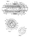
- the filter illustrated in the drawings incorporates a pressure-regulator feature which automatically prevents an undue build-up of pressure within the filter, and also a back-flushable feature which permits the filter body to be cleaned in a quick and convenient manner without opening the filter housing.
- a pressure-regulator feature which automatically prevents an undue build-up of pressure within the filter
- a back-flushable feature which permits the filter body to be cleaned in a quick and convenient manner without opening the filter housing.
- the pressure-regulated back-flushable filter illustrated in the drawings comprises a central tube 2 and a housing 4 enclosing the central tube and defining an internal chamber 6 therewith in which is disposed a filter body, generally designated 8.
- End 2a of the central tube 2 constitutes the inlet end connectible to the fluid supply line, (e.g., a water irrigation line), and end 2b constitutes the outlet end of the tube through which the irrigating water flows after being filtered by the filter body 8 within the housing 4.
- a solid plug 10 is fixed, e.g., by one or more pins 12, within the central tube 2 adjacent its inlet end 2a.
- Central tube 2 is formed with a circular array of inlet openings 14 at the inlet side of plug 10, and with a plurality of circular arrays of outlet openings 16 at the outlet side of the plug. It will thus be seen that plug 10 directs the water from the inlet end 2a through the inlet openings 14 into chamber 6, then through the filter body 8 to the oulet openings 16 and out through the outlet end 2b.
- the filter housing 4 is of cylindrical shape and is comprised of two sections 4a, 4b having flanged confronting faces clamped together by a strap-clamp 18.
- the inlet end of housing section 4a is formed with a central opening 20a for accomodating the inlet end 2a of the central tube 2; and the outlet end of housing section 4b is also formed with a central opening 20b for accomodating the outlet end 2b of the central tube.
- opening 20a in housing section 4a is of substantially the same diameter as the outer diameter of the central tube 2, but opening 20b in housing section 4b is of slightly larger diameter and accomodates a bushing 22 which is fixed by pin 23, to central tube 2.
- Bushing 22 includes an enlarged head 22a engageable with the outer face of housing section 4b and a tubular section 22b surrounding the central tube 22 and slidably receiving the outlet end of housing section 4b.
- the two openings 20a, 20b in the housing sections 4a, 4b are circumscribed by annular ribs 24a, 24b for receiving sealing rings 25a, 25b.
- Filter body 8 includes a plurality of annular filter discs 26 and a plurality of annular partition discs 28, all arranged as a stack and slidably received on the outer face of the central tube 2.
- the filter discs 26 may be of any known construction including ribbed side faces defining filtering passages for filtering the water passing between the discs.
- the partition discs 28 divide the filter discs 26 into a plurality of filter sections each including a plurality of filter discs 26 between a pair of partition discs 28
- the partition discs 28 have internal diameters which are substantially the same as the outer diameter of the central tube 2, but the filter discs 26 have inner diameters which are substantially larger.
- each of the filter sections between two partition discs 28 defines a compartment 30a-30f between the outer face of the central tube and the inner faces of the filter discs 26.
- the first compartment 30a is bounded by a valve member 32 for a reason to be described below
- the last compartment 30f is bounded by an end disc 34 received over the tubular section 22b of bushing 22.
- End disc 34 is formed with a circular array of axially-extending fingers 36 (Fig. 3), to space the end disc from the inner face of the end wall of housing secion 4b, and thereby to provide a space 38 for the fluid to flow during a back-flusing operation, as will be described below.
- Central tube 2 is formed with a circular array of the outlet opening 16 aligned with each of the compartment 30a-30f of the filter body 8.
- filter body 8 is formed with six filter sections each including a compartment 30a-30f, and therefore the central tube is formed with six circular arrays of outlet openings 16.
- valve member 32 cooperates with the inlet opening 14 through the central tube 2 in order to regulate the pressure within the housing 4.
- Valve member 32 comprises a tubular section 32a slidably received over the outer face of central tube 2, and an annular flange 32b having an outer diameter substantially equal to that of the filter discs 26 and partition discs 28.
- the annular flange 32b of valve member 32 is pressed against the stack of filter discs 26 by a spring 40 interposed between the annular flange 32b and another disc 42 at the inlet end of the housing 4 bearing against annular rib 24a.
- disc 42 is more particularly illustrated in Fig. 2. It is also of annular shape, having an inner diameter substantially the same as the outer diameter of the central tube 2. However, disc 42 is formed with a pair of inwardly-extending projections 44 received within recesses 46 formed in the outer face of the central tube 2. Each recess 46 is very short, extending axially of the tube for a distance substantially equal to the thickness of disc 42. Disc 42 is also formed with a plurality of outer fingers 48 engageable with the inner face of housing section 4a.
- Disc 42 is further formed with a plurality of radially-extending slots 50, starting at its outer face and terminating short of its inner face. These slots are staggered with a plurality of further radially-extending slots 51 starting at the inner face of the disc and terminating short of the outer face.
- This slotted construction of disc 42 imparts sufficient flexibility to the disc to permit it to be expanded in the radial direction a sufficient distance to unseat its inner projections 44 from the short recesses 46 formed in the outer face of the central tube 2, when it is desired to perform a back-flushing operation as will be described more particularly below.
- the outer fingers 48 of disc 42 are received in the spaces between a plurality of axially-extending, circumferentially-spaced ribs 52 formed on the inner face of housing section 4a.
- the inner face of housing section 4b is similarly formed with a plurality of axially-extending circumferentially-spaced ribs 54.
- the ribs of both set 52, 54 are spaced from each other several times their widths so that there is ample space between ribs 52 for receiving the outer fingers 48 of disc 42.
- both sets of ribs 52, 54 include projections 52a, 54a projecting from the clamped confronting ends of the two housing sections 4a, 4b, which projections interfit with each other when the two sections are clamped together as shown in Fig. 1.
- Disc 42 is called a coupling disc, since it is effective to couple or decouple the housing 4 with respect to the central tube 2.
- the inner projections 44 of coupling disc 42 are seated within the short recesses 46 formed in the outer surface of the central tube 2, and thereby couple the housing 4 to the central tube, permitting only restricted movement (rightwardly, Fig. 1) of the housing with respect to the central tube according to the contracting of spring 40.
- slots 50, 51 permit the coupling disc to expand radially and to unseat its projections 44 from the short recesses 46 in the outer face of the central tube 2, thereby decoupling the housing from the central tube and permitting the housing unrestricted movement (rightwardly, Fig. 1) with respect to the central tube.
- the latter operation is performed when it is desired to back-flush the filtr, in a manner described below particularly with reference to Fig. 4.
- the pressure-regulated back-flushable filter illustrated in the drawings operates as follows:
- Figs. 1 and 2 illustrate the condition of the filter during the normal filter mode, wherein projections 44 of the coupling disc 42 are seated within the short recesses 46 formed in the outer face of the central tube 2.
- coupling disc 42 forms a seat for one end of spring 40, the opposite end of the spring bearing against the annular flange 32b of valve member 32, urging that valve member rightwardly, and also thereby urging the filter discs 26 and partition discs 28 leftwardly limited by the fingers 36 of end discs 34 bearing against the inner face of housing section 4b.
- the filter discs 26 are pressed firmly against each other in the form of a tight stack so as to filter the water inletted via the inlet end 2a of the central tube 2.
- the water passes through inlet openings 14 into chamber 6l; through the spaces between the axial ribs 52a, 52b formed on the inner faces of the housing sections 4a, 4b; radially through the filter discs 26 of the plural sections of the filter body 8 defined by the partition discs 28; through the compartment 30a-30f of the filter body; through the outlet openings 16 aligned with these compartments; and finally through the outlet end 2b of the central tube.
- Fig. 1 also illustrates the condition of the parts when the pressure within housing 4 is below a predetermined maximum pressure. Should the pressure within housing 4 begin to rise above its predetermined maximum, a differential pressure is produced within housing 4 tending to move the housing rightwardly against the force of spring 40. That is, since opening 20a formed in housing section 4a is of smaller diameter than opening 20b formed in housing section 4b, the larger surface area of the end wall of housing section 4a, as compared to that of housing section 4b, will cause the pressure of the water within the housing to exert a larger force against the end wall of housing section 4a than that against the end wall of housing section 4b. This differential pressure will move the two housing sections (clamped by clamping band 18) in the rightward direction.
- valve member 32 moves rightwardly to cover part of the inlet openings 14, thereby restricting the cross-sectional area of these openings and the flow of the water inletted into chamber 6, until the pressure within the filter housing is reduced to the predetermined maximum pressure.
- This arrangement thus prevents the pressure within the housing from rising above a predetermined maximum value during the normal filtering mode of operation.
- the maximum pressure is determined by spring 40; this spring can be selected to cause valve member to completely close inlet openings 14, so that the device also acts as a shut-off valve.
- Th filter housing 4 is permitted to move unrestrictedly rightwardly along the length of the central tube.
- the rightward movement of the housing is assisted by the above-described differential pressure produced within the housing by the larger surface area of the end wall of housing section 4a exposed to the fluid pressure as compared to the surface area of the end wall of section 4b. This force may be sufficient by itself to move housing 4 rightwardly, or it may aid the user in manually moving housing 4 rightwardly.
- housing 4 moves rightwardly with respect to the central tube 2 until compartment 30a of filter body 8 becomes aligned with the inlet openings 14 in the central tube; when the housing is so positioned, disc 34 of the filter body 8 has cleared the tubular section 22b of bushing 22 fixed to the central tube 2.
- compartment 30a of the filter body 8, and the filter discs 26 constituting this section of the filter body are thoroughly back-flushed of dirt particles that have accumulated on the outer faces, and between the side faces, of the filter discs 26 of this section of the filter body.
- Housing 4 is then moved further rightwardly, either automatically by the above-described differential pressure, or manually and aided by the differential pressure, to bring the compartment 30b of the next section of the filter body 8 into alignment with inlet openings 14, whereupon that section of the filter body is back-flushed in the same manner as described above. Continued movement of housing 4 rightwardly successively back-flushes the remaining filter sections via their compartments 30c, 30d, 30e, 30f.
- housing 4 When the complete filter body 8 has thus been cleaned by back-flushing, housing 4 is manually moved leftwardly to its inital position against flange 22a of bushing 22 and is rotated to seat the inner projections 44 of coupling disc 42 back into the short recesses 46 in the outer face of the central tube 2, whereupon the cleaned filter thereafter operates according to the above-described filter mode of operation.
Landscapes
- Chemical Kinetics & Catalysis (AREA)
- Chemical & Material Sciences (AREA)
- Filtration Of Liquid (AREA)
- Macromonomer-Based Addition Polymer (AREA)
- Fluid-Pressure Circuits (AREA)
- Ink Jet (AREA)
- Details Of Valves (AREA)
- Filtering Of Dispersed Particles In Gases (AREA)
- Lubrication Details And Ventilation Of Internal Combustion Engines (AREA)
- Medical Preparation Storing Or Oral Administration Devices (AREA)
- Electrical Discharge Machining, Electrochemical Machining, And Combined Machining (AREA)
- Oscillators With Electromechanical Resonators (AREA)
- Networks Using Active Elements (AREA)
Priority Applications (1)
| Application Number | Priority Date | Filing Date | Title |
|---|---|---|---|
| AT87630208T ATE70987T1 (de) | 1986-10-16 | 1987-10-15 | Rueckspuelfilter und druckregler dazu. |
Applications Claiming Priority (2)
| Application Number | Priority Date | Filing Date | Title |
|---|---|---|---|
| IL80341A IL80341A (en) | 1986-10-16 | 1986-10-16 | Pressure-regulator and back-flushable filter inculding same |
| IL80341 | 1986-10-16 |
Publications (2)
| Publication Number | Publication Date |
|---|---|
| EP0265368A1 true EP0265368A1 (de) | 1988-04-27 |
| EP0265368B1 EP0265368B1 (de) | 1992-01-02 |
Family
ID=11057213
Family Applications (1)
| Application Number | Title | Priority Date | Filing Date |
|---|---|---|---|
| EP87630208A Expired - Lifetime EP0265368B1 (de) | 1986-10-16 | 1987-10-15 | Rückspülfilter und Druckregler dazu |
Country Status (9)
| Country | Link |
|---|---|
| US (1) | US4806217A (de) |
| EP (1) | EP0265368B1 (de) |
| AT (1) | ATE70987T1 (de) |
| AU (1) | AU597735B2 (de) |
| DE (1) | DE3775704D1 (de) |
| ES (1) | ES2029283T3 (de) |
| GR (1) | GR3004125T3 (de) |
| IL (1) | IL80341A (de) |
| ZA (1) | ZA877741B (de) |
Families Citing this family (24)
| Publication number | Priority date | Publication date | Assignee | Title |
|---|---|---|---|---|
| IL74873A (en) * | 1985-04-10 | 1990-07-12 | Drori Mordeki | Multiple disc type filter and disc construction useful therein |
| US4995968A (en) * | 1985-11-21 | 1991-02-26 | Snelling Peter J | Filters |
| US5858231A (en) * | 1987-02-10 | 1999-01-12 | Drori; Mordeki | Filter apparatus |
| US4978450A (en) * | 1986-02-11 | 1990-12-18 | Mordeki Drori | Filtering element |
| DE3727277A1 (de) * | 1986-08-20 | 1988-02-25 | Toshiba Ceramics Co | Verfahren und vorrichtung zum filtern einer fluessigkeit |
| IL83329A (en) * | 1987-07-26 | 1991-08-16 | Drori Mordeki | Filter apparatus |
| US5015379A (en) * | 1988-03-16 | 1991-05-14 | Mordeki Drori | Coiled filter strip with upstream and downstream butt ends |
| US5290445A (en) * | 1988-05-27 | 1994-03-01 | Pall Corporation | Filtering apparatus |
| IL93160A (en) * | 1990-01-24 | 1992-12-01 | Rosenberg Peretz | Back-flushable filter |
| US5228993A (en) * | 1990-02-09 | 1993-07-20 | Mordeki Drori | Cleanable filter system with longitudinally movable and rotatable cleaning member |
| US5151175A (en) * | 1991-07-12 | 1992-09-29 | Royal Claude S | System to automatically drain filter backwash water |
| US5242581A (en) * | 1992-03-30 | 1993-09-07 | Facet Quantek, Inc. | Shut-off valve |
| IL110586A (en) * | 1994-03-28 | 2000-07-26 | Super Disc Filters Ltd | Back-flushable filters |
| AUPM921894A0 (en) * | 1994-11-04 | 1994-11-24 | Medical Plastics (Aust) Pty Ltd | Filtering apparatus |
| US7192528B2 (en) * | 2004-02-17 | 2007-03-20 | Jnm Technologies, Inc. | Self-cleaning filter apparatus |
| US20060086820A1 (en) * | 2004-10-27 | 2006-04-27 | Byers Bruce E | Self-cleaning fluid delivery system |
| US20060151363A1 (en) * | 2005-01-07 | 2006-07-13 | Claudiu-Ioan Ratiu | Modular disc filter with integrated and automated self-flushing operator |
| US20070194150A1 (en) * | 2005-10-19 | 2007-08-23 | Orbit Irrigation Products, Inc. | Combined valve, filter, and regulator irrigation apparatus |
| US20070119974A1 (en) * | 2005-10-19 | 2007-05-31 | Orbit Irrigation Products, Inc. | Combined valve, filter, and regulator irrigation apparatus |
| US20070262168A1 (en) * | 2005-10-19 | 2007-11-15 | Ericksen Kent C | Combined valve, filter, and regulator irrigation apparatus |
| US8231794B2 (en) * | 2007-07-05 | 2012-07-31 | Spintek Filtration, Inc. | Water filtration system |
| US20090229675A1 (en) * | 2008-03-17 | 2009-09-17 | Scot Hoskisson | In-line filter/flow regulator/anti-siphon device |
| WO2011112872A2 (en) | 2010-03-12 | 2011-09-15 | Levitt David J | Fluid filtration and particle concentration device and methods |
| US10286338B2 (en) | 2014-01-13 | 2019-05-14 | Spiral Water Technologies, Inc. | Flow control features for fluid filtration device and methods |
Citations (5)
| Publication number | Priority date | Publication date | Assignee | Title |
|---|---|---|---|---|
| US3368680A (en) * | 1965-05-04 | 1968-02-13 | Rosaen Filter Co | Filter with element subassembly |
| US3542202A (en) * | 1969-04-11 | 1970-11-24 | Technical Fabricators | Filter unit |
| GB2137895A (en) * | 1983-04-14 | 1984-10-17 | Mordeki Drori | Backwashable filter |
| EP0149931A1 (de) * | 1983-11-17 | 1985-07-31 | GEORGES MOATTI, Société Anonyme | Filter mit mehreren Aufnahmekammern für das Filtrat und für eine andere Flüssigkeit welche durch den Rückstand den Hauptfiltrierung gebildet ist |
| EP0205407A2 (de) * | 1985-06-10 | 1986-12-17 | Mordeki Drori | Scheibenfilter |
Family Cites Families (8)
| Publication number | Priority date | Publication date | Assignee | Title |
|---|---|---|---|---|
| US2002717A (en) * | 1932-06-20 | 1935-05-28 | Robuell Company | Reducing valve |
| US2488649A (en) * | 1944-11-16 | 1949-11-22 | Bendix Aviat Corp | Suction throttling valve |
| US3890999A (en) * | 1972-12-15 | 1975-06-24 | Eugene D Moskow | Fluid pressure regulator |
| IL55622A0 (en) * | 1978-09-22 | 1978-12-17 | Drori Mordeki | Backflushing fluid filter |
| AU5250379A (en) * | 1978-11-17 | 1980-05-22 | Mordeki Drori | Backwashable filter |
| IL57119A0 (en) * | 1979-04-23 | 1979-07-25 | Rosenberg P | Ressure regultor |
| US4592839A (en) * | 1983-06-09 | 1986-06-03 | Peretz Rosenberg | Multiple-disc filter |
| US4561465A (en) * | 1983-09-06 | 1985-12-31 | Aeroquip Corporation | Axial flow pressure regulator |
-
1986
- 1986-10-16 IL IL80341A patent/IL80341A/xx not_active IP Right Cessation
-
1987
- 1987-10-06 US US07/105,072 patent/US4806217A/en not_active Expired - Fee Related
- 1987-10-15 AT AT87630208T patent/ATE70987T1/de not_active IP Right Cessation
- 1987-10-15 ES ES198787630208T patent/ES2029283T3/es not_active Expired - Lifetime
- 1987-10-15 DE DE8787630208T patent/DE3775704D1/de not_active Expired - Lifetime
- 1987-10-15 AU AU79819/87A patent/AU597735B2/en not_active Ceased
- 1987-10-15 ZA ZA877741A patent/ZA877741B/xx unknown
- 1987-10-15 EP EP87630208A patent/EP0265368B1/de not_active Expired - Lifetime
-
1992
- 1992-03-24 GR GR920400507T patent/GR3004125T3/el unknown
Patent Citations (5)
| Publication number | Priority date | Publication date | Assignee | Title |
|---|---|---|---|---|
| US3368680A (en) * | 1965-05-04 | 1968-02-13 | Rosaen Filter Co | Filter with element subassembly |
| US3542202A (en) * | 1969-04-11 | 1970-11-24 | Technical Fabricators | Filter unit |
| GB2137895A (en) * | 1983-04-14 | 1984-10-17 | Mordeki Drori | Backwashable filter |
| EP0149931A1 (de) * | 1983-11-17 | 1985-07-31 | GEORGES MOATTI, Société Anonyme | Filter mit mehreren Aufnahmekammern für das Filtrat und für eine andere Flüssigkeit welche durch den Rückstand den Hauptfiltrierung gebildet ist |
| EP0205407A2 (de) * | 1985-06-10 | 1986-12-17 | Mordeki Drori | Scheibenfilter |
Also Published As
| Publication number | Publication date |
|---|---|
| IL80341A0 (en) | 1987-01-30 |
| DE3775704D1 (de) | 1992-02-13 |
| ES2029283T3 (es) | 1992-08-01 |
| EP0265368B1 (de) | 1992-01-02 |
| ZA877741B (en) | 1988-10-26 |
| GR3004125T3 (de) | 1993-03-31 |
| ATE70987T1 (de) | 1992-01-15 |
| AU597735B2 (en) | 1990-06-07 |
| US4806217A (en) | 1989-02-21 |
| IL80341A (en) | 1989-03-31 |
| AU7981987A (en) | 1988-04-21 |
Similar Documents
| Publication | Publication Date | Title |
|---|---|---|
| EP0265368B1 (de) | Rückspülfilter und Druckregler dazu | |
| US4295963A (en) | Backwashable fluid filter | |
| US4632757A (en) | Filters cleanable by reverse flushing | |
| US4592839A (en) | Multiple-disc filter | |
| US3988244A (en) | Cartridge filter | |
| US4683060A (en) | Multiple-disc type filters | |
| DE60222826T2 (de) | Filter mit zwei Abschnitten zur Abgasnachbehandlung | |
| JP2872403B2 (ja) | 液体フィルター用逃がし弁 | |
| US4614581A (en) | Backwashable filter | |
| US3289841A (en) | Bidirectional filter | |
| EP0857271B1 (de) | Durchflussregelventil mit nicht-verstopfender mehrstufendrosselung | |
| JPS631085B2 (de) | ||
| EP0202186B1 (de) | Gleichstromfilter und insbesondere dafür gebräuchliche Filterscheiben | |
| US4714552A (en) | In-line fluid filtering devices and disc-filters useful in such devices | |
| WO1997021480A1 (en) | A filter element for a fluid filter | |
| US4572784A (en) | Multiple-disc filters | |
| US5171433A (en) | Back-flushable filter | |
| GB1562361A (en) | Industrial water filter with spiral housing | |
| US5575911A (en) | Back-flushable filter having valved flusing pathway | |
| US5558761A (en) | Fluid filtering unit with movable collector for cleaning | |
| US12048889B2 (en) | Filter assembly for a servovalve | |
| USRE34218E (en) | Easily-cleanable filters | |
| US4598730A (en) | Flow control valve | |
| JP6824532B2 (ja) | インラインストレーナ | |
| JPH0344250Y2 (de) |
Legal Events
| Date | Code | Title | Description |
|---|---|---|---|
| PUAI | Public reference made under article 153(3) epc to a published international application that has entered the european phase |
Free format text: ORIGINAL CODE: 0009012 |
|
| AK | Designated contracting states |
Kind code of ref document: A1 Designated state(s): AT BE CH DE ES FR GB GR IT LI NL |
|
| 17P | Request for examination filed |
Effective date: 19881010 |
|
| 17Q | First examination report despatched |
Effective date: 19900919 |
|
| GRAA | (expected) grant |
Free format text: ORIGINAL CODE: 0009210 |
|
| AK | Designated contracting states |
Kind code of ref document: B1 Designated state(s): AT BE CH DE ES FR GB GR IT LI NL |
|
| PG25 | Lapsed in a contracting state [announced via postgrant information from national office to epo] |
Ref country code: NL Effective date: 19920102 Ref country code: AT Effective date: 19920102 |
|
| REF | Corresponds to: |
Ref document number: 70987 Country of ref document: AT Date of ref document: 19920115 Kind code of ref document: T |
|
| REF | Corresponds to: |
Ref document number: 3775704 Country of ref document: DE Date of ref document: 19920213 |
|
| ET | Fr: translation filed | ||
| ITF | It: translation for a ep patent filed | ||
| NLV1 | Nl: lapsed or annulled due to failure to fulfill the requirements of art. 29p and 29m of the patents act | ||
| REG | Reference to a national code |
Ref country code: ES Ref legal event code: FG2A Ref document number: 2029283 Country of ref document: ES Kind code of ref document: T3 |
|
| PLBE | No opposition filed within time limit |
Free format text: ORIGINAL CODE: 0009261 |
|
| STAA | Information on the status of an ep patent application or granted ep patent |
Free format text: STATUS: NO OPPOSITION FILED WITHIN TIME LIMIT |
|
| 26N | No opposition filed | ||
| REG | Reference to a national code |
Ref country code: GR Ref legal event code: FG4A Free format text: 3004125 |
|
| PGFP | Annual fee paid to national office [announced via postgrant information from national office to epo] |
Ref country code: GB Payment date: 19971013 Year of fee payment: 11 |
|
| PGFP | Annual fee paid to national office [announced via postgrant information from national office to epo] |
Ref country code: CH Payment date: 19971023 Year of fee payment: 11 |
|
| PGFP | Annual fee paid to national office [announced via postgrant information from national office to epo] |
Ref country code: GR Payment date: 19971024 Year of fee payment: 11 Ref country code: ES Payment date: 19971024 Year of fee payment: 11 |
|
| PGFP | Annual fee paid to national office [announced via postgrant information from national office to epo] |
Ref country code: BE Payment date: 19971030 Year of fee payment: 11 |
|
| PGFP | Annual fee paid to national office [announced via postgrant information from national office to epo] |
Ref country code: FR Payment date: 19971113 Year of fee payment: 11 |
|
| PGFP | Annual fee paid to national office [announced via postgrant information from national office to epo] |
Ref country code: DE Payment date: 19971115 Year of fee payment: 11 |
|
| PG25 | Lapsed in a contracting state [announced via postgrant information from national office to epo] |
Ref country code: GB Free format text: LAPSE BECAUSE OF NON-PAYMENT OF DUE FEES Effective date: 19981015 |
|
| PG25 | Lapsed in a contracting state [announced via postgrant information from national office to epo] |
Ref country code: ES Free format text: LAPSE BECAUSE OF NON-PAYMENT OF DUE FEES Effective date: 19981016 |
|
| PG25 | Lapsed in a contracting state [announced via postgrant information from national office to epo] |
Ref country code: LI Free format text: LAPSE BECAUSE OF NON-PAYMENT OF DUE FEES Effective date: 19981031 Ref country code: GR Free format text: LAPSE BECAUSE OF NON-PAYMENT OF DUE FEES Effective date: 19981031 Ref country code: CH Free format text: LAPSE BECAUSE OF NON-PAYMENT OF DUE FEES Effective date: 19981031 Ref country code: BE Free format text: LAPSE BECAUSE OF NON-PAYMENT OF DUE FEES Effective date: 19981031 |
|
| BERE | Be: lapsed |
Owner name: ROSENBERG PERETZ Effective date: 19981031 |
|
| GBPC | Gb: european patent ceased through non-payment of renewal fee |
Effective date: 19981015 |
|
| REG | Reference to a national code |
Ref country code: CH Ref legal event code: PL |
|
| PG25 | Lapsed in a contracting state [announced via postgrant information from national office to epo] |
Ref country code: FR Free format text: LAPSE BECAUSE OF NON-PAYMENT OF DUE FEES Effective date: 19990630 |
|
| REG | Reference to a national code |
Ref country code: FR Ref legal event code: ST |
|
| PG25 | Lapsed in a contracting state [announced via postgrant information from national office to epo] |
Ref country code: DE Free format text: LAPSE BECAUSE OF NON-PAYMENT OF DUE FEES Effective date: 19990803 |
|
| REG | Reference to a national code |
Ref country code: ES Ref legal event code: FD2A Effective date: 19991113 |
|
| PG25 | Lapsed in a contracting state [announced via postgrant information from national office to epo] |
Ref country code: IT Free format text: LAPSE BECAUSE OF NON-PAYMENT OF DUE FEES;WARNING: LAPSES OF ITALIAN PATENTS WITH EFFECTIVE DATE BEFORE 2007 MAY HAVE OCCURRED AT ANY TIME BEFORE 2007. THE CORRECT EFFECTIVE DATE MAY BE DIFFERENT FROM THE ONE RECORDED. Effective date: 20051015 |