EP0265405B1 - Appareil pour mélanger un matériau sec avec un liquide - Google Patents
Appareil pour mélanger un matériau sec avec un liquide Download PDFInfo
- Publication number
- EP0265405B1 EP0265405B1 EP87850307A EP87850307A EP0265405B1 EP 0265405 B1 EP0265405 B1 EP 0265405B1 EP 87850307 A EP87850307 A EP 87850307A EP 87850307 A EP87850307 A EP 87850307A EP 0265405 B1 EP0265405 B1 EP 0265405B1
- Authority
- EP
- European Patent Office
- Prior art keywords
- vessel
- pipe
- liquid
- mixing
- powder material
- Prior art date
- Legal status (The legal status is an assumption and is not a legal conclusion. Google has not performed a legal analysis and makes no representation as to the accuracy of the status listed.)
- Expired - Lifetime
Links
- 239000007788 liquid Substances 0.000 title claims abstract description 28
- 239000000463 material Substances 0.000 title claims abstract description 25
- 238000002156 mixing Methods 0.000 title claims abstract description 24
- 239000000843 powder Substances 0.000 claims abstract description 28
- 239000002002 slurry Substances 0.000 claims abstract description 18
- 238000003801 milling Methods 0.000 claims description 14
- 230000001788 irregular Effects 0.000 claims description 2
- 239000011268 mixed slurry Substances 0.000 claims 2
- 239000000203 mixture Substances 0.000 abstract description 13
- 238000000034 method Methods 0.000 abstract description 7
- 239000000428 dust Substances 0.000 description 9
- AXCZMVOFGPJBDE-UHFFFAOYSA-L calcium dihydroxide Chemical compound [OH-].[OH-].[Ca+2] AXCZMVOFGPJBDE-UHFFFAOYSA-L 0.000 description 7
- 239000000920 calcium hydroxide Substances 0.000 description 7
- 229910001861 calcium hydroxide Inorganic materials 0.000 description 7
- 235000011116 calcium hydroxide Nutrition 0.000 description 7
- XLYOFNOQVPJJNP-UHFFFAOYSA-N water Substances O XLYOFNOQVPJJNP-UHFFFAOYSA-N 0.000 description 7
- OSGAYBCDTDRGGQ-UHFFFAOYSA-L calcium sulfate Chemical compound [Ca+2].[O-]S([O-])(=O)=O OSGAYBCDTDRGGQ-UHFFFAOYSA-L 0.000 description 4
- 239000007787 solid Substances 0.000 description 4
- 230000002745 absorbent Effects 0.000 description 3
- 239000002250 absorbent Substances 0.000 description 3
- 238000003756 stirring Methods 0.000 description 3
- 235000008733 Citrus aurantifolia Nutrition 0.000 description 2
- 235000011941 Tilia x europaea Nutrition 0.000 description 2
- GBAOBIBJACZTNA-UHFFFAOYSA-L calcium sulfite Chemical compound [Ca+2].[O-]S([O-])=O GBAOBIBJACZTNA-UHFFFAOYSA-L 0.000 description 2
- 239000001175 calcium sulphate Substances 0.000 description 2
- 235000011132 calcium sulphate Nutrition 0.000 description 2
- 239000004295 calcium sulphite Substances 0.000 description 2
- 235000010261 calcium sulphite Nutrition 0.000 description 2
- 238000000576 coating method Methods 0.000 description 2
- 239000010881 fly ash Substances 0.000 description 2
- 239000004571 lime Substances 0.000 description 2
- 239000002245 particle Substances 0.000 description 2
- 239000000725 suspension Substances 0.000 description 2
- 229910000746 Structural steel Inorganic materials 0.000 description 1
- NINIDFKCEFEMDL-UHFFFAOYSA-N Sulfur Chemical compound [S] NINIDFKCEFEMDL-UHFFFAOYSA-N 0.000 description 1
- 239000005864 Sulphur Substances 0.000 description 1
- 230000015572 biosynthetic process Effects 0.000 description 1
- 238000010276 construction Methods 0.000 description 1
- 238000001739 density measurement Methods 0.000 description 1
- 230000007613 environmental effect Effects 0.000 description 1
- 230000001747 exhibiting effect Effects 0.000 description 1
- 230000005484 gravity Effects 0.000 description 1
- 239000000383 hazardous chemical Substances 0.000 description 1
- 231100000206 health hazard Toxicity 0.000 description 1
- 239000012535 impurity Substances 0.000 description 1
- 230000007257 malfunction Effects 0.000 description 1
- 238000000465 moulding Methods 0.000 description 1
- 239000012779 reinforcing material Substances 0.000 description 1
- 239000000126 substance Substances 0.000 description 1
Images
Classifications
-
- B—PERFORMING OPERATIONS; TRANSPORTING
- B01—PHYSICAL OR CHEMICAL PROCESSES OR APPARATUS IN GENERAL
- B01F—MIXING, e.g. DISSOLVING, EMULSIFYING OR DISPERSING
- B01F35/00—Accessories for mixers; Auxiliary operations or auxiliary devices; Parts or details of general application
- B01F35/71—Feed mechanisms
- B01F35/717—Feed mechanisms characterised by the means for feeding the components to the mixer
- B01F35/71775—Feed mechanisms characterised by the means for feeding the components to the mixer using helical screws
-
- B—PERFORMING OPERATIONS; TRANSPORTING
- B01—PHYSICAL OR CHEMICAL PROCESSES OR APPARATUS IN GENERAL
- B01F—MIXING, e.g. DISSOLVING, EMULSIFYING OR DISPERSING
- B01F35/00—Accessories for mixers; Auxiliary operations or auxiliary devices; Parts or details of general application
- B01F35/71—Feed mechanisms
-
- B—PERFORMING OPERATIONS; TRANSPORTING
- B01—PHYSICAL OR CHEMICAL PROCESSES OR APPARATUS IN GENERAL
- B01F—MIXING, e.g. DISSOLVING, EMULSIFYING OR DISPERSING
- B01F35/00—Accessories for mixers; Auxiliary operations or auxiliary devices; Parts or details of general application
- B01F35/71—Feed mechanisms
- B01F35/712—Feed mechanisms for feeding fluids
-
- B—PERFORMING OPERATIONS; TRANSPORTING
- B01—PHYSICAL OR CHEMICAL PROCESSES OR APPARATUS IN GENERAL
- B01F—MIXING, e.g. DISSOLVING, EMULSIFYING OR DISPERSING
- B01F35/00—Accessories for mixers; Auxiliary operations or auxiliary devices; Parts or details of general application
- B01F35/71—Feed mechanisms
- B01F35/717—Feed mechanisms characterised by the means for feeding the components to the mixer
- B01F35/71755—Feed mechanisms characterised by the means for feeding the components to the mixer using means for feeding components in a pulsating or intermittent manner
Definitions
- the present invention relates to an apparatus for mixing a dry, or a substantially dry powder material with a liquid to form a slurry.
- a vessel which contains the liquid and which is provided with agitating or stirring means, the powder material being added to the liquid either continuously or intermittently.
- a slurry containing calcium hydroxide is charged to a contact reactor, where the slurry reacts with the sulphur-containing impurities.
- this contact reactor is operated in accordance with the "wet-dry” method there is obtained from the reactor a residual dust which can be said to comprise a mixture of calcium sulphite, calcium sulphate, calcium hydroxide and fly ash.
- the fresh absorbent is dry slaked lime
- the lime, recycle dust and water are mixed together to form a slurry having a dry solids content of ca 35%.
- this lime normally has a dry solids content of 20-25% and is mixed in the mixing vessel with recycle dust to a dry solids content of ca 35 %.
- the mixing of dry powder with a liquid is connected with two basically different technical problems.
- the mixing operation is often creating environmental problems and perhaps even health hazards for the people employed.
- the quality of the product, i.e. the suspension or solution is often uneven and the removed product may contain hard lumps disturbing the function of the equipment where the suspension or solution is to be used later.
- a technical problem resides also in the provision, with the aid of simple means, of equipment, which will enable dry powder material to be mixed with a liquid, in a mixing vessel provided with agitating or stirring means without generating a dusty atmosphere.
- a further technical problem is one of providing means whereby any lumps or deposits that do form in the mixing vessel, in spite of measures taken to the contrary, are disintegrated or ground to pieces, thus getting a size not causing malfunction in the equipment where the mixed product is to be used.
- Another technical problem is one of providing simple milling means that also will assist the mixing of the dry powder with the liquid.
- the present invention provides a solution to one or more of the aforesaid technical problems, and relates to an apparatus of the kind stated in the preamble of claim 1 by means of which apparatus a dry or substantially dry powder material, particularly dry material taken from a contact reactor or calcium hydroxide, can be mixed with a liquid, in the form of water, to form a slurry.
- a dry or substantially dry powder material particularly dry material taken from a contact reactor or calcium hydroxide
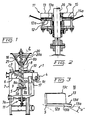
- the present invention thus relates to an apparatus 1 intended for mixing a dry or substantially dry powder material 2, in the form of calcium sulphite, calcium sulphate, calcium hydroxide and fly ash with a liquid, in the form of water, charged through a pipe 3 such as to form a slurry which can be removed through an outlet 4, while using a vessel 7 which is provided with agitating or stirring means 5 and which contains the liquid 6 introduced thereinto through the pipe 3 and in which the powder material 2 is intended to be charged into the liquid, either continuously or intermittently.
- a pipe 8 having a diameter of 150 mm is arranged to co-act with the vessel 7 in a manner such that one end of the pipe 8 is located at a depth of ca 500 mm beneath the surface 9a of the mixture 9 and that the powder material 2 is passed through the pipe 8 and into a mixing zone 9b with the aid of a mechanical auxiliary device.
- the mechanical auxiliary device comprises a conveyor, for example a screw conveyor 10, which fills the whole of the interior of the pipe 8.
- the said one end 8a of the pipe and the agitating means 5 are located closely adjacent one another, for instance at a distance apart of less than 50 mm, preferably less than 25 mm.
- the bottom 7a of the vessel 7 tapers downwardly adjacent the mixing zone 9b, such as to co-act with a milling means 11 which is arranged in the narrowest, lowermost part of the vessel and which is intended to crush small lumps formed in the vessel 7 or at some other location, particularly agglomerates or lumps whose density exceeds the density of the mixture 9, or such lumps as those which are urged downwardly by the agitating means 5.
- a milling means 11 which is arranged in the narrowest, lowermost part of the vessel and which is intended to crush small lumps formed in the vessel 7 or at some other location, particularly agglomerates or lumps whose density exceeds the density of the mixture 9, or such lumps as those which are urged downwardly by the agitating means 5.
- FIG 2 is an enlarged view of the milling means 11 illustrated in Figure 1, and it will be seen from Figure 2 that the milling means comprises a circular, lower plate 12 having an irregular or fluted upper surface 12a and diametrically positioned, rotatable vanes 13 and 14 spaced at a small distance above the plate 12.
- a space 15 which is adapted to correspond to the maximum permitted particle size of the powder material. This distance shall therefore be less than 2 mm.
- the vanes 13 and 14 are positioned obliquely and directed in the rotational direction, so as to be able to press and crush small lumps against the upper surface 12a of the plate 12.
- the slurry mix 9c is removed from the vessel through an outlet 4 located at or adjacent the surface 9a of the mix.
- a screen 17 Arranged in the vessel 7 adjacent the outlet 4 is a screen 17 which separates the mixing zone 9b in the vessel 7 from the slurry outlet 4.
- the pipe 8 extends vertically, although there is nothing to prevent the pipe from being slightly inclined with the screw conveyor 7 filling the interior of the pipe.
- the other end 8b of the pipe co-acts with a funnel-shaped filling device 20, which includes one or more scraper bars 21 capable of being moved along the inner surface 20a of the filling device.
- the scraper bars 21 are attached to the shaft 16 via support means, such as to be driven by said shaft.
- the agitating means 5 comprises two vanes, referenced 5a and 5b, which are located essentially in the centre of the vessel or centrally of the mix 9.
- the milling means is provided with two vanes, referenced 13 and 14, which are inclined slightly to the vertical plane.
- the angle at which the vanes are inclined is such as to ensure that a lump entering between the leading part of the vane and the bottom edge 13a thereof will be crushed to pieces against the surface 12a.
- the pipe end 8a is preferably located beneath the surface 9a at a distance greater than 30cm, but preferably not greater than half the depth of the mix.
- the agitating means preferably has a diameter such as to cover at least 25% of the diameter of the vessel, but not more than 50%.
- the screen 17 is arranged to extend beyond the agitating means 5 on the side thereof where it meets the rotation created by the agitating means, but is much shorter on the downstream side.
- the screen does not extend sealingly against the wall in the vessel.
- a gap of 10-20 mm affords a certain amount of rotation behind the screen such as to prevent the formation of deposits or coatings deriving from stationary slurry 9c.
- the relationship between the flows of material entering the mixing vessel is determined by taking density measurements in the outlet 4 or in a subsequent storage tank, not shown.
- the amount of powderous material charged is controlled through metering means (not shown) located above the funnel 20.
- the powder material is charged in a quantity such that it only fills a small part of the cross-section of the pipe 8, so that there is effected within the lower part 8a of the pipe an initial mixing of dry powder with a previous mixture in the mixing zone 9b, with the aid of the end part of the screw conveyor, whereafter mixing is effected with the aid of the agitating means 5, which steers the mixture down towards the milling means 11.
- This initial mixing process takes place partially in a vertical direction within a limited space within the pipe end 8a, therewith preventing the emission of dust.
- a vane 13 forming part of the milling means 11 is illustrated in Figure 3.
- the vane consists of L-shaped angle iron which is slightly inclined so that the lower bottom surface 13a of the lower part 13d forms a wedge-shaped space with the surface 12a.
- This wedge-shaped space may have an angle of "a" of less than 20° perferably less than 10°.
- the upper part 13c is intended to push large lumps in its forward direction, but also contributes towards improving the mixture.
Landscapes
- Chemical & Material Sciences (AREA)
- Chemical Kinetics & Catalysis (AREA)
- Mixers Of The Rotary Stirring Type (AREA)
- Preparation Of Clay, And Manufacture Of Mixtures Containing Clay Or Cement (AREA)
- Processing And Handling Of Plastics And Other Materials For Molding In General (AREA)
- Detergent Compositions (AREA)
Claims (10)
- Appareil pour mélanger un matériau en poudre sec ou sensiblement sec (2) avec un liquide (3) pour former une suspension (9c) comprend un récipient (7), comportant un moyen de passage (4) pour le retrait de la suspension mixée finalement (9c), un moyen agitateur (5) qui est agencé à l'intérieur du récipient, un tuyau (8) s'étendant verticalement ou sensiblement verticalement dans le récipient et un convoyeur (10) remplissant l'intérieur du tuyau pour fournir en matériau en poudre le moyen agitateur à travers le tuyau, caractérisé en ce que l'extrémité inférieure du tuyau (8) et le moyen agitateur (5) sont agencés étroitement au voisinage l'un de l'autre, en ce que le fond du récipient (7) est formé pour se rétrécir vers le bas et en ce que le moyen de broyage (11) pour broyer des morceaux formés dans le réservoir ou bien à une autre localisation, est positionné dans la partie la plus étroite du récipient.
- Appareil selon la revendication 1, caractérisé en ce que le convoyeur est un convoyeur à vis (10).
- Appareil selon la revendication 1 ou 2, caractérisé en ce que le moyen de broyage (11) comprend une plaque (12) ayant une surface irrégulière, par exemple une plaque cannelée, et des vannes rotatives (13, 14), localisées à une petite distance au-dessus de la plaque.
- Appareil selon la revendication 3, caractérisé en ce que les vannes (13, 14) sont positionnées obliquement et dirigées dans la direction rotationnelle de façon à comprimer et broyer des petits morceaux contre la surface supérieure (12a) de la plaque (12).
- Appareil selon la revendication 3 ou 4, caractérisé en ce que les vannes (13, 14) ont une section transversale en forme de L incluant une partie dirigée horizontalement qui se rétrécit à partir du centre de rotation.
- Appareil selon l'une quelconque des revendications 2 à 5, caractérisé en ce que le convoyeur à vis (10), le moyen agitateur (5) et le moyen de broyage (11) sont entraînés par un et le même arbre (16).
- Appareil selon la revendication 1, caractérisé en ce qu'un écran (17) pour séparer une zone de mixage (9b) dans le récipient (7) de la suspension mixée finalement (9c) est agencé au voisinage du moyen de passage (4) dans ledit réservoir.
- Appareil selon la revendication 1, caractérisé en ce que l'autre, extrémité supérieure du tuyau (8) coopère avec un dispositif de remplissage en forme d'entonnoir (20).
- Appareil selon la revendication 8, caractérisé en ce que le dispositif de remplissage en forme d'entonnoir (20) comprend une ou plusieurs barres racleuses (21) qui sont déplaçables le long de la surface interne (20a) dudit dispositif.
- Appareil selon la revendication 6 et 9, caractérisé en ce que les barres recleuses (21) sont entraînées par ledit arbre (16).
Priority Applications (1)
| Application Number | Priority Date | Filing Date | Title |
|---|---|---|---|
| AT87850307T ATE68105T1 (de) | 1986-10-20 | 1987-10-14 | Vorrichtung zum mischen von trockenem material mit einer fluessigkeit. |
Applications Claiming Priority (2)
| Application Number | Priority Date | Filing Date | Title |
|---|---|---|---|
| SE8604468A SE458665B (sv) | 1986-10-20 | 1986-10-20 | Foerfarande och anordning foer att blanda torrt pulverformigt material med en vaetska foer att bilda en slurry |
| SE8604468 | 1986-10-20 |
Publications (2)
| Publication Number | Publication Date |
|---|---|
| EP0265405A1 EP0265405A1 (fr) | 1988-04-27 |
| EP0265405B1 true EP0265405B1 (fr) | 1991-10-09 |
Family
ID=20366004
Family Applications (1)
| Application Number | Title | Priority Date | Filing Date |
|---|---|---|---|
| EP87850307A Expired - Lifetime EP0265405B1 (fr) | 1986-10-20 | 1987-10-14 | Appareil pour mélanger un matériau sec avec un liquide |
Country Status (6)
| Country | Link |
|---|---|
| US (1) | US4824032A (fr) |
| EP (1) | EP0265405B1 (fr) |
| AT (1) | ATE68105T1 (fr) |
| DE (1) | DE3773611D1 (fr) |
| ES (1) | ES2026205T3 (fr) |
| SE (1) | SE458665B (fr) |
Families Citing this family (12)
| Publication number | Priority date | Publication date | Assignee | Title |
|---|---|---|---|---|
| FI93002C (fi) * | 1992-03-17 | 1996-01-03 | Outokumpu Ecoenergy Oy | Menetelmä ja laite anaerobiseen bioreaktoriin syötettävän seoksen valmistamiseksi |
| DE19950743A1 (de) * | 1999-10-21 | 2001-04-26 | Harald Kniele | KKM-Mischer |
| US6712496B2 (en) * | 2001-07-26 | 2004-03-30 | The Procter & Gamble Company | Auger fed mixer apparatus and method of using |
| US6994464B2 (en) * | 2002-04-11 | 2006-02-07 | Mobius Technologies, Inc | Control system and method for continuous mixing of slurry with removal of entrained bubbles |
| US20030233937A1 (en) * | 2002-04-11 | 2003-12-25 | Mobius Technologies, Inc., A California Corporation | Apparatus and method for continuously removing air from a mixture of ground polyurethane particles and a polyol liquid |
| US7029162B2 (en) * | 2002-04-11 | 2006-04-18 | Mobius Technologies, Inc. | Process and apparatus for continuous mixing of slurry with removal of entrained bubbles |
| US6860289B2 (en) * | 2002-04-11 | 2005-03-01 | Robert Donald Villwock | Surge tank |
| US20030227817A1 (en) * | 2002-04-11 | 2003-12-11 | Mobius Technologies, Inc., A California Corporation | Mixer |
| US7105146B2 (en) * | 2003-03-04 | 2006-09-12 | Chemco Systems L.P. | Method and apparatus for hydration of calcium oxide |
| DE102013213246A1 (de) * | 2013-07-05 | 2015-01-08 | Robert Bosch Gmbh | Ventil-Mühle-Anordnung |
| CN106965341B (zh) * | 2017-05-11 | 2018-10-12 | 上海电力学院 | 粘弹性高分子聚合物水溶液配置装置 |
| CN114797619B (zh) * | 2022-06-20 | 2022-09-20 | 江苏浦士达环保科技股份有限公司 | 一种活性炭生产用混料装置 |
Family Cites Families (4)
| Publication number | Priority date | Publication date | Assignee | Title |
|---|---|---|---|---|
| US2890039A (en) * | 1953-11-02 | 1959-06-09 | Karl Schmidt Metallschmelzwerk | Apparatus for the introduction of substances into liquids of high specific gravity |
| US3175807A (en) * | 1961-02-28 | 1965-03-30 | Johns Manville | Method and apparatus for preparing a fiber-reinforced molding composition |
| US4225092A (en) * | 1977-11-22 | 1980-09-30 | Microprocess Ltd. | Annular grinding mill |
| US4438885A (en) * | 1980-02-07 | 1984-03-27 | Hedlund Manufacturing Co., Inc. | Manure loader |
-
1986
- 1986-10-20 SE SE8604468A patent/SE458665B/sv not_active IP Right Cessation
-
1987
- 1987-10-14 EP EP87850307A patent/EP0265405B1/fr not_active Expired - Lifetime
- 1987-10-14 DE DE8787850307T patent/DE3773611D1/de not_active Expired - Lifetime
- 1987-10-14 ES ES198787850307T patent/ES2026205T3/es not_active Expired - Lifetime
- 1987-10-14 AT AT87850307T patent/ATE68105T1/de not_active IP Right Cessation
- 1987-10-16 US US07/109,040 patent/US4824032A/en not_active Expired - Fee Related
Also Published As
| Publication number | Publication date |
|---|---|
| DE3773611D1 (de) | 1991-11-14 |
| ATE68105T1 (de) | 1991-10-15 |
| SE8604468L (sv) | 1988-04-21 |
| SE458665B (sv) | 1989-04-24 |
| EP0265405A1 (fr) | 1988-04-27 |
| ES2026205T3 (es) | 1992-04-16 |
| US4824032A (en) | 1989-04-25 |
| SE8604468D0 (sv) | 1986-10-20 |
Similar Documents
| Publication | Publication Date | Title |
|---|---|---|
| EP0265405B1 (fr) | Appareil pour mélanger un matériau sec avec un liquide | |
| CN110315638A (zh) | 一种干混砂浆混合搅拌装置 | |
| US4779992A (en) | Lime slaker | |
| KR101977682B1 (ko) | 고순도 초미립자의 액상 소석회 제조장치 | |
| US4619052A (en) | Process and apparatus for drying and classifying particulate granulate material | |
| US2915412A (en) | Method of handling and conditioning paper making clay for use | |
| US4079863A (en) | Apparatus for dispensing material in bulk | |
| US3036737A (en) | Surge tank for feeding finely divided flocculent solids | |
| US2509431A (en) | Dispensing fluidized pulverulent materials | |
| CN209934541U (zh) | 一种固体肥料混合装置 | |
| CN209425817U (zh) | 一种水泥浆制备装置 | |
| US4662894A (en) | Process for producing a coal-water mixture | |
| CN1032869C (zh) | 转炉炼钢湿法除尘污泥回收利用装置 | |
| CN107774146B (zh) | 一种用于制备催化剂浆液的设备及应用 | |
| CN216367740U (zh) | 一种淤泥粉碎及物料混合搅拌一体化装置 | |
| JP2003136100A (ja) | 水分を含む廃棄物の処理装置 | |
| US845190A (en) | Method of hydrating lime. | |
| US4280665A (en) | Solids eliminator | |
| CN208302772U (zh) | 一种反应釜中的搅拌轴 | |
| CN208302773U (zh) | 一种反应釜内固体颗粒粉碎结构 | |
| CN221386055U (zh) | 一种化工生产用液粉混合搅拌器 | |
| CN108249465B (zh) | 利用电石渣制取氢氧化钙的生产设备及其生产工艺 | |
| US4730787A (en) | Method of separating solids by simultaneous comminution and agglomeration | |
| CN219580761U (zh) | 一种煤矿药量检测装置 | |
| CN219784914U (zh) | 一种磷石膏粉生产用磷石膏破碎装置 |
Legal Events
| Date | Code | Title | Description |
|---|---|---|---|
| PUAI | Public reference made under article 153(3) epc to a published international application that has entered the european phase |
Free format text: ORIGINAL CODE: 0009012 |
|
| AK | Designated contracting states |
Kind code of ref document: A1 Designated state(s): AT BE CH DE ES FR GB GR IT LI LU NL SE |
|
| 17P | Request for examination filed |
Effective date: 19880427 |
|
| 17Q | First examination report despatched |
Effective date: 19890627 |
|
| RAP1 | Party data changed (applicant data changed or rights of an application transferred) |
Owner name: ABB FLAEKT AB |
|
| GRAA | (expected) grant |
Free format text: ORIGINAL CODE: 0009210 |
|
| AK | Designated contracting states |
Kind code of ref document: B1 Designated state(s): AT BE CH DE ES FR GB GR IT LI LU NL SE |
|
| PG25 | Lapsed in a contracting state [announced via postgrant information from national office to epo] |
Ref country code: SE Effective date: 19911009 Ref country code: NL Effective date: 19911009 Ref country code: LI Effective date: 19911009 Ref country code: GR Free format text: LAPSE BECAUSE OF FAILURE TO SUBMIT A TRANSLATION OF THE DESCRIPTION OR TO PAY THE FEE WITHIN THE PRESCRIBED TIME-LIMIT Effective date: 19911009 Ref country code: CH Effective date: 19911009 Ref country code: BE Effective date: 19911009 Ref country code: AT Effective date: 19911009 |
|
| REF | Corresponds to: |
Ref document number: 68105 Country of ref document: AT Date of ref document: 19911015 Kind code of ref document: T |
|
| PG25 | Lapsed in a contracting state [announced via postgrant information from national office to epo] |
Ref country code: LU Free format text: LAPSE BECAUSE OF NON-PAYMENT OF DUE FEES Effective date: 19911031 |
|
| REF | Corresponds to: |
Ref document number: 3773611 Country of ref document: DE Date of ref document: 19911114 |
|
| ITF | It: translation for a ep patent filed | ||
| ET | Fr: translation filed | ||
| REG | Reference to a national code |
Ref country code: CH Ref legal event code: PL |
|
| NLV1 | Nl: lapsed or annulled due to failure to fulfill the requirements of art. 29p and 29m of the patents act | ||
| REG | Reference to a national code |
Ref country code: ES Ref legal event code: FG2A Ref document number: 2026205 Country of ref document: ES Kind code of ref document: T3 |
|
| PLBE | No opposition filed within time limit |
Free format text: ORIGINAL CODE: 0009261 |
|
| STAA | Information on the status of an ep patent application or granted ep patent |
Free format text: STATUS: NO OPPOSITION FILED WITHIN TIME LIMIT |
|
| 26N | No opposition filed | ||
| PGFP | Annual fee paid to national office [announced via postgrant information from national office to epo] |
Ref country code: GB Payment date: 19971006 Year of fee payment: 11 |
|
| PGFP | Annual fee paid to national office [announced via postgrant information from national office to epo] |
Ref country code: FR Payment date: 19971009 Year of fee payment: 11 |
|
| PGFP | Annual fee paid to national office [announced via postgrant information from national office to epo] |
Ref country code: ES Payment date: 19971017 Year of fee payment: 11 Ref country code: DE Payment date: 19971017 Year of fee payment: 11 |
|
| PG25 | Lapsed in a contracting state [announced via postgrant information from national office to epo] |
Ref country code: GB Free format text: LAPSE BECAUSE OF NON-PAYMENT OF DUE FEES Effective date: 19981014 |
|
| PG25 | Lapsed in a contracting state [announced via postgrant information from national office to epo] |
Ref country code: ES Free format text: LAPSE BECAUSE OF EXPIRATION OF PROTECTION Effective date: 19981015 |
|
| GBPC | Gb: european patent ceased through non-payment of renewal fee |
Effective date: 19981014 |
|
| PG25 | Lapsed in a contracting state [announced via postgrant information from national office to epo] |
Ref country code: FR Free format text: LAPSE BECAUSE OF NON-PAYMENT OF DUE FEES Effective date: 19990630 |
|
| REG | Reference to a national code |
Ref country code: FR Ref legal event code: ST |
|
| PG25 | Lapsed in a contracting state [announced via postgrant information from national office to epo] |
Ref country code: DE Free format text: LAPSE BECAUSE OF NON-PAYMENT OF DUE FEES Effective date: 19990803 |
|
| REG | Reference to a national code |
Ref country code: ES Ref legal event code: FD2A Effective date: 20010201 |
|
| PG25 | Lapsed in a contracting state [announced via postgrant information from national office to epo] |
Ref country code: IT Free format text: LAPSE BECAUSE OF NON-PAYMENT OF DUE FEES;WARNING: LAPSES OF ITALIAN PATENTS WITH EFFECTIVE DATE BEFORE 2007 MAY HAVE OCCURRED AT ANY TIME BEFORE 2007. THE CORRECT EFFECTIVE DATE MAY BE DIFFERENT FROM THE ONE RECORDED. Effective date: 20051014 |