EP0265521A1 - Rotor de moteur de fond a entrainement par vis, ainsi que son procede et dispositif de realisation - Google Patents
Rotor de moteur de fond a entrainement par vis, ainsi que son procede et dispositif de realisation Download PDFInfo
- Publication number
- EP0265521A1 EP0265521A1 EP86902578A EP86902578A EP0265521A1 EP 0265521 A1 EP0265521 A1 EP 0265521A1 EP 86902578 A EP86902578 A EP 86902578A EP 86902578 A EP86902578 A EP 86902578A EP 0265521 A1 EP0265521 A1 EP 0265521A1
- Authority
- EP
- European Patent Office
- Prior art keywords
- rotor
- shaping
- screw
- shaping element
- tube block
- Prior art date
- Legal status (The legal status is an assumption and is not a legal conclusion. Google has not performed a legal analysis and makes no representation as to the accuracy of the status listed.)
- Granted
Links
- 238000000034 method Methods 0.000 title claims description 23
- 238000007493 shaping process Methods 0.000 claims description 70
- 230000008878 coupling Effects 0.000 claims description 24
- 238000010168 coupling process Methods 0.000 claims description 24
- 238000005859 coupling reaction Methods 0.000 claims description 24
- 238000004519 manufacturing process Methods 0.000 claims description 23
- 230000009471 action Effects 0.000 claims description 4
- 230000006835 compression Effects 0.000 claims description 4
- 238000007906 compression Methods 0.000 claims description 4
- 239000012530 fluid Substances 0.000 abstract 1
- 230000009467 reduction Effects 0.000 description 8
- 238000005553 drilling Methods 0.000 description 6
- 239000002184 metal Substances 0.000 description 6
- 239000003921 oil Substances 0.000 description 4
- 238000005452 bending Methods 0.000 description 3
- 230000006378 damage Effects 0.000 description 3
- 239000013013 elastic material Substances 0.000 description 3
- 239000007788 liquid Substances 0.000 description 3
- 238000003754 machining Methods 0.000 description 3
- 238000013459 approach Methods 0.000 description 2
- 230000005540 biological transmission Effects 0.000 description 2
- 238000005520 cutting process Methods 0.000 description 2
- 238000011010 flushing procedure Methods 0.000 description 2
- 238000003801 milling Methods 0.000 description 2
- 239000002480 mineral oil Substances 0.000 description 2
- 235000010446 mineral oil Nutrition 0.000 description 2
- 238000003825 pressing Methods 0.000 description 2
- 230000008569 process Effects 0.000 description 2
- 239000011435 rock Substances 0.000 description 2
- 229910001220 stainless steel Inorganic materials 0.000 description 2
- 239000010935 stainless steel Substances 0.000 description 2
- 241000566515 Nedra Species 0.000 description 1
- 238000000137 annealing Methods 0.000 description 1
- 230000000712 assembly Effects 0.000 description 1
- 238000000429 assembly Methods 0.000 description 1
- 230000015572 biosynthetic process Effects 0.000 description 1
- 239000011248 coating agent Substances 0.000 description 1
- 238000000576 coating method Methods 0.000 description 1
- 230000006866 deterioration Effects 0.000 description 1
- 230000000694 effects Effects 0.000 description 1
- 238000005516 engineering process Methods 0.000 description 1
- 238000010438 heat treatment Methods 0.000 description 1
- 230000006872 improvement Effects 0.000 description 1
- 238000009931 pascalization Methods 0.000 description 1
- 230000002093 peripheral effect Effects 0.000 description 1
- 238000007789 sealing Methods 0.000 description 1
- 238000004904 shortening Methods 0.000 description 1
- 230000007704 transition Effects 0.000 description 1
- 238000003466 welding Methods 0.000 description 1
Images


Classifications
-
- E—FIXED CONSTRUCTIONS
- E21—EARTH OR ROCK DRILLING; MINING
- E21B—EARTH OR ROCK DRILLING; OBTAINING OIL, GAS, WATER, SOLUBLE OR MELTABLE MATERIALS OR A SLURRY OF MINERALS FROM WELLS
- E21B4/00—Drives for drilling, used in the borehole
- E21B4/02—Fluid rotary type drives
-
- F—MECHANICAL ENGINEERING; LIGHTING; HEATING; WEAPONS; BLASTING
- F01—MACHINES OR ENGINES IN GENERAL; ENGINE PLANTS IN GENERAL; STEAM ENGINES
- F01C—ROTARY-PISTON OR OSCILLATING-PISTON MACHINES OR ENGINES
- F01C1/00—Rotary-piston machines or engines
- F01C1/08—Rotary-piston machines or engines of intermeshing engagement type, i.e. with engagement of co- operating members similar to that of toothed gearing
- F01C1/10—Rotary-piston machines or engines of intermeshing engagement type, i.e. with engagement of co- operating members similar to that of toothed gearing of internal-axis type with the outer member having more teeth or tooth-equivalents, e.g. rollers, than the inner member
- F01C1/101—Moineau-type
-
- F—MECHANICAL ENGINEERING; LIGHTING; HEATING; WEAPONS; BLASTING
- F04—POSITIVE - DISPLACEMENT MACHINES FOR LIQUIDS; PUMPS FOR LIQUIDS OR ELASTIC FLUIDS
- F04C—ROTARY-PISTON, OR OSCILLATING-PISTON, POSITIVE-DISPLACEMENT MACHINES FOR LIQUIDS; ROTARY-PISTON, OR OSCILLATING-PISTON, POSITIVE-DISPLACEMENT PUMPS
- F04C2230/00—Manufacture
- F04C2230/20—Manufacture essentially without removing material
- F04C2230/27—Manufacture essentially without removing material by hydroforming
-
- Y—GENERAL TAGGING OF NEW TECHNOLOGICAL DEVELOPMENTS; GENERAL TAGGING OF CROSS-SECTIONAL TECHNOLOGIES SPANNING OVER SEVERAL SECTIONS OF THE IPC; TECHNICAL SUBJECTS COVERED BY FORMER USPC CROSS-REFERENCE ART COLLECTIONS [XRACs] AND DIGESTS
- Y10—TECHNICAL SUBJECTS COVERED BY FORMER USPC
- Y10T—TECHNICAL SUBJECTS COVERED BY FORMER US CLASSIFICATION
- Y10T29/00—Metal working
- Y10T29/49—Method of mechanical manufacture
- Y10T29/49229—Prime mover or fluid pump making
- Y10T29/49236—Fluid pump or compressor making
- Y10T29/49242—Screw or gear type, e.g., Moineau type
-
- Y—GENERAL TAGGING OF NEW TECHNOLOGICAL DEVELOPMENTS; GENERAL TAGGING OF CROSS-SECTIONAL TECHNOLOGIES SPANNING OVER SEVERAL SECTIONS OF THE IPC; TECHNICAL SUBJECTS COVERED BY FORMER USPC CROSS-REFERENCE ART COLLECTIONS [XRACs] AND DIGESTS
- Y10—TECHNICAL SUBJECTS COVERED BY FORMER USPC
- Y10T—TECHNICAL SUBJECTS COVERED BY FORMER US CLASSIFICATION
- Y10T29/00—Metal working
- Y10T29/49—Method of mechanical manufacture
- Y10T29/49316—Impeller making
- Y10T29/49336—Blade making
- Y10T29/49339—Hollow blade
-
- Y—GENERAL TAGGING OF NEW TECHNOLOGICAL DEVELOPMENTS; GENERAL TAGGING OF CROSS-SECTIONAL TECHNOLOGIES SPANNING OVER SEVERAL SECTIONS OF THE IPC; TECHNICAL SUBJECTS COVERED BY FORMER USPC CROSS-REFERENCE ART COLLECTIONS [XRACs] AND DIGESTS
- Y10—TECHNICAL SUBJECTS COVERED BY FORMER USPC
- Y10T—TECHNICAL SUBJECTS COVERED BY FORMER US CLASSIFICATION
- Y10T29/00—Metal working
- Y10T29/49—Method of mechanical manufacture
- Y10T29/49805—Shaping by direct application of fluent pressure
Definitions
- the present invention relates to drilling technology and, more particularly, relates to one of the main assemblies of screw-bottom drive for drilling oil and gas wells, namely the rotor of a screw-bottom drive and method of making the same.
- a screw-type soleplate drive with a multi-start rotor is known, which is designed in the form of a multi-start all-metal screw in which the number of turns of the screw surface (the screw teeth) is more than one (SU copyright document No. 926209).
- the rotor is housed in a stator that has a multi-start internal helical surface with a number of gears that exceeds the number of gears of the rotor by one; this screw surface is produced on a covering from a resiliently elastic material, such as rubber, glued to the inner surface of the stator housing.
- the rotor axis is offset relative to the stator axis coinciding with the drive axis by an eccentricity amount that is half the height of the rotor and stator teeth, while the axial pitch ratio of the screw teeth of the rotor and the stator is equal to the number of teeth ratio of these parts.
- the rotor executes an orbital movement, the rotor axis rotating counterclockwise relative to the stator axis at an angular velocity ⁇ 1 , while the rotor itself rotates clockwise around its own axis at an angular velocity of ⁇ 2 .
- the angular velocity ⁇ 1 is equal to the angular velocity ⁇ 2 multiplied by the number of rotor teeth, and the centrifugal force acting on the rotor is proportional to the rotor mass and the square of the angular velocity ⁇ 1 .
- the multi-speed rotor of the drive described above is manufactured according to a gear milling method using a metal-cutting tool, such as a hob cutter.
- This method is expensive, not powerful enough, it does not guarantee a high surface quality of the rotor teeth and requires complicated and expensive equipment - machine tools and tools to carry it out.
- the working surfaces of the rotor must then be polished or ground, which is what a complicated configuration of the rotor surface and a large length of the rotor is a difficult technological task.
- a screw downhole sole drive with a multi-start hollow rotor is also known.
- the rotor is rigidly connected to a coupling by means of a threaded connection (see the book by Gusman MT, inter alia, "screw-borehole sole drives for drilling holes", 1981, “Nedra”, (Moscow), p . 125 to 188).
- the metal in the middle of the rotor is removed.
- the metal is removed by drilling a central hole in the rotor. This can also be achieved by using a thick-walled tube block for the manufacture of the rotor.
- the centrifugal forces acting on the rotor can be somewhat reduced by reducing the dynamics of the transverse vibrations of the rotor and of the entire drive.
- a significant amount of metal remains in the body of the teeth of the rotor in its peripheral area, which leads to the creation of significant centrifugal forces during operation of the drive and to a shortening of its service life.
- the connection of the rotor with an articulated or a flexible shaft by means of a coupling provided with threaded connections is not reliable, because during operation of the drive under the action of dynamic forces a decoupling can take place.
- the design of the rotor as a closed whole part or from a thick-walled tube also requires a high consumption of stainless steel.
- the drives equipped with the rotor described above are characterized by a relatively low efficiency and not a high output, because the work of these drives results in high mechanical losses caused by the self-heating of the stator rubber.
- the method consists in the deformation of a pipe block on a shaping screw surface due to the pressure of a flowing medium on the pipe block.
- the method is carried out with the aid of a device in whose housing a shaping element with a shaping surface is accommodated, within which the tube block is located.
- the shaping screw surface is provided on the inner surface of the shaping element, which simultaneously fulfills the function of the housing and consists of several axial partial surfaces.
- the pressure of the flowing medium is generated in the cavity of the tube block arranged within the sealed shaping element.
- the shaping of the rotor of a single screw pump takes place in several stages, with the tube block being lifted out of the shaping element for annealing treatment after each stage in order to reduce the hardness and to remove internal stresses.
- the disadvantages of the known method and the devices for its implementation are low quality counted the outer working surface of the rotor, on which traces of the division of the shaping element are left, an additional machining of the outer surface of the rotor using special equipment being required to eliminate these traces.
- Another disadvantage of the above-mentioned method and the device is the complicated production of the inner surfaces of the divisible shaping element as well as a complicated covering of the shaping screw surfaces in parting planes. These disadvantages are particularly noticeable in the manufacture of rotors with a large ratio of length to diameter, which makes it impossible to manufacture multi-speed rotors using the method described above.
- Another disadvantage of the known method is that a high hydrostatic pressure of the flowing medium is required because the tube block is subjected to significant tensile deformations. This also results in a high energy intensity of the process.
- the invention has for its object to provide a rotor for a screw-bottom drive and a method for producing this rotor and a device for carrying out the method, which make it possible to improve the energy characteristic of the drive by realizing design features of the rotor, reduce the friction losses and increase the performance in the manufacture of the rotor.
- a rotor of a bottom hole drive which is designed in the form of a multi-start screw with a number of teeth of the screw surface of over 1 and rigidly connected to a clutch is designed according to the invention as a hollow body with a substantially constant wall thickness, the ratio between the length of the outer line of the rotor cross section and the length of the circumference described relative to this outer line being essentially in a range from 0.9 to 1.05.
- Such a design of the rotor enables an improvement in the energy characteristic of the drive, a reduction in the transverse vibrations, an increase in the strength of the rotor under torsional and bending stresses, a reduction in the mass and the metal intensity of the rotor, a reduction in the consumption of stainless steel and a Improving the quality of the rotor to be manufactured.
- the essence of the method for producing the rotor is that a tube block is deformed on a shaping surface by the pressure action of a flowing medium, and according to the invention a shaping element, the outer surface of which is a shaping surface, is arranged inside the tube block while the pressure of the flowing medium is applied to the pipe block from the outside.
- the shape of the pipe block preferably carried out in two stages, in the first stage the tube block is given the shape of a screw polyhedron with rounded tips, in which the diameter of the circumference is slightly larger than the diameter of the circumference of the finished rotor and the number of side surfaces of the number of gears Helical surface of the rotor is equal, and the final shaping of the rotor screw surface is carried out in the second stage.
- the essence of the device for the manufacture of the rotor according to the method set forth above is that a shaping element with a shaping surface is accommodated in the housing of the device, and according to the invention the shaping element within the Housing is attached to centering bushings, the shaping surface is carried out on the outer surface of the shaping element, the centering bushings having fitting sections which are set up for a sliding fit of the ends of the tube block.
- each centering bushing has a shoulder adjoining its fitting section, against which the pipe block located on the fitting section is supported and in which an annular groove is provided, the width of the groove being essentially the same as the thickness of the pipe block, and in that A seal is housed in the groove.
- the shaping element in some cases it is necessary for the shaping element to be arranged interchangeably in the housing and for a shaping element for preforming to be provided which is in the form of a screw polyhedron with rounded tips, in which the diameter of the circumference is somewhat larger than the diameter the circumference of the shaping element for final shaping and the number of side surfaces is equal to the number of gears of the rotor screw surface.
- the rotor 1 is one of the main parts of a screw-hole sole drive (FIG. 1) and is designed in the form of a multi-start screw provided with external screw teeth 2 with a number of gears (teeth) of the screw surface of more than 1.
- the rotor 1 is arranged within a stator 3, which has a coating 4 made of a resilient, elastic material such as rubber.
- the Inner screw surface of the lining 4 forms screw teeth 5, the number of which exceeds the number of teeth of the rotor 1 by one.
- the axis O1 (FIG. 2) of the rotor 1 is offset relative to the axis 0 2 of the stator 3 by the eccentricity quantity "e".
- the rotor 1 (FIG. 1)
- the bearing assembly 7 contains axle bearings and radial bearings (not shown) for absorbing borehole bottom loads.
- a rock destruction tool 9 is connected to the lower end of the shaft 6 of the bearing assembly 7.
- the stator 3 of the drive is connected to the lower end of a drill pipe 11 by means of a transition piece 10.
- the rotor 1 (FIGS. 3, 4) is designed as a hollow body according to the present invention and contains a tubular casing 12 (housing) and a coupling 13 (FIG. 3) rigidly connected thereto for connection to the flexible shaft 8 (FIG. 1 ).
- the coupling 13 (Fig. 3) is provided with elements 14, e.g. with threads, for connecting the flexible shaft 8.
- the attachment can also be done by other known methods, e.g. by welding, using a cone.
- the coupling 13 is preferably fastened in the tubular casing 12 by compressing the tubular casing 12 on the profiled outer surface of the coupling 13, on which recesses 15 are provided. This is done according to the procedure described above.
- the recesses 15 can have different shapes, ie they can be designed as radial, non-continuous openings, longitudinal or transverse grooves or flattenings, ring or spiral grooves and their combinations. It is important that those formed on the profiled outer surface of the coupling 13 during the compression of the end section of the tubular casing 12 Approaches 16 with the recesses 15 of the coupling 13 for transmitting the torsional moment and the axial load in engagement.
- FIGS. 3 and 5 show an embodiment of the recess 15 as an annular groove with a diameter d, which is arranged eccentrically with respect to the cylindrical outer surface 17 of the coupling 13.
- the ratio between the length of the outer line 18 in the cross section of the rotor 1 and the length of the circumference 19 described relative to this outer line is essentially in a range from 0.9 to 1.05. Under otherwise identical conditions, the selection of this ratio below 0.9 leads to a reduction in the energy characteristics of the screw drive, based on the torsional moment and the power (due to a reduction in the number of rotor gears) to a reduction in the torsional and bending strength of the rotor, which is designed as a hollow body as well as a deterioration in the manufacturing quality of the rotor according to the method according to the invention and by means of the device according to the invention, which are described below because folds form and the geometric shape of the rotor is violated.
- the rotor according to the invention has the following mode of operation.
- a flushing liquid is supplied from the surface of the day via the drill pipe 11 (FIG. 1)
- the rotor 1 is rotated under the action of an unbalanced liquid pressure on its side screw surface, and it rolls on the teeth of the stator 3.
- the torsional moment to be generated on the rotor and the axial load are transmitted to the shaft 6 of the support assembly 7 via the flexible shaft 8, which is connected to the rotor 1 via the coupling 13.
- the rotation is transmitted from the shaft 6 of the bearing group 7 to the rock destruction tool 9.
- the above-described screw bottom drive rotor is made as follows.
- the shaping element with the shaping multi-start external screw surface is inserted into a tube shell, which has previously been machined on the outer surface to the required surface quality (ground, polished), the ends of the tube shell are hermetically sealed against the shaping element, while simultaneously centering them guaranteed and pressure is generated from the outside around the pipe shell by a flowing medium, eg mineral oil.
- a flowing medium eg mineral oil
- the shaping of the rotor teeth is expedient according to the present method performed in two stages.
- the tube shell is partially deformed to the incomplete tooth height, giving the tube block the shape of a screw polyhedron with rounded tips, and in the second stage, the screw surface of the rotor is finally shaped.
- the use of a reduced size of the radial deformation ensures that the screw surface is produced in a quality-appropriate form, which has no folds and no other injuries.
- the first stage can be carried out at a reduced pressure of the flowing medium, because in this stage the task of overcoming the stability of the cylindrical shape of the tube block and preforming the screw surface, which has the same number of gears and the same pitch of the helical line as in the finished rotor, is solved.
- the tube block in the form of a screw polyhedron obtained after machining in the first stage is subjected to a final shaping for the production of the screw surface of the rotor by the same method, uz a pressure of the flowing medium is generated from the outside around the tube block with the shaping element located therein.
- a method for producing the rotor proves to be optimal, in which a connection of its tubular casing 12 to the coupling 13 is made simultaneously with the shape of the screw surface of the rotor.
- the coupling 13 with a profiled outer surface is inserted into the tubular casing before it is compressed; the outer surface is provided with recesses of this or that shape, for example with radial non-through openings, longitudinal or transverse grooves or flats, ring or screw grooves or combinations thereof.
- lugs are formed on the inner surface thereof which engage with the cutouts engage the coupling, thereby ensuring transmission of the torsional moment generated on the tubular casing of the rotor and the axial forces to the coupling and then to the flexible shaft.
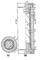
- the method described above for producing the rotor of a screw-type borehole sole drive can be carried out by means of a device which is shown in longitudinal section in FIG. 6 and in cross section in FIG. 7.
- the device contains a thick-walled tubular housing 20, in which a shaping element 21 is arranged, which is centered relative to the housing 20 by means of centering bushes 22, 22 '(FIG. 6).
- the shaping outer surface of the shaping element 21 is designed in the form of screw teeth 23, which have the same direction and pitch of the helix with the rotor to be manufactured, the equidistant size being equal to the wall thickness ⁇ f (FIG. 4) of the tube block 24.
- fitting sections 25 are provided, on which the tube blocks 24 are placed with their ends.
- the centering bushes 22, 22 ' are provided at the points of their coupling with the housing 20 with seals 26, 26' which e.g. are in the form of 0-shaped rubber rings.
- the centering bushing 22 has a shoulder adjoining the fitting section 25 with an annular end groove 27, in which there is a seal 28 made of rubber or another elastic material.
- the width of the groove is essentially the same as the thickness "d" of the tube block 24.
- the pipe block 24 is arranged on the fitting sections 25 (only one fitting section is shown in FIG. 6) of the centering bushes 22, 22 'in such a way that the end faces of the pipe block 24 are supported on the end faces of the seals 28 with a certain axial tensioning over the rubber .
- the axial distortion (fastening) of the tube block 24, the centering bushes 22, 22 'with the seals 28 (only one seal is shown in FIG. 6) and the shaping element 21 is by means of the inner end faces 29 of round nuts 30 (in FIG. is only one) Round nut reproduced) guaranteed, which are screwed onto the end thread of the housing 20.
- a cavity 31 for the supply of a flowing medium under pressure is formed between the outer surface of the tube block 24 and the inner surface of the housing 20.
- openings 32 and 33 are provided in the housing 20.
- the shaping element 21 (FIG. 6) is designed to be exchangeable in two stages during the manufacture of the rotor.
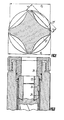
- the shaping element 21 'used for preforming (FIG. 8) is designed in the form of a screw polyhedron, which in cross section has the shape of a polyhedron with rounded tips and a reduced height h of the screw teeth and an enlarged outer diameter d 2 compared to the sizes h 2 and d 3 of the shaping element 21 used for the final shaping. 8 shows superimposed outer lines of the cross sections of the shaping elements 21 'and 21 for the preliminary and final shaping.
- the device is assembled and operated as follows.
- the shaping element 21 is introduced into the tube block 24 of the rotor, the surface of which has previously been machined (ground, polished) to the surface quality required for the rotor.
- a centering bushing 22 ′ is attached to one end of the shaping element 21, the end section of the tube block 24 being brought up to the fitting section on the centering bushing 22 ′ at the same time.
- the second centering bushing 22 is attached to the free end of the shaping element 21, at the same time the fitting section of this centering bushing in the pipe block 24, but the outer surface of the centering bushing 22 in the Housing 20 are introduced.
- the assembled parts are fastened in the housing 20 by means of the nuts 30 until the end faces of the tube block 24 are pressed into the body of the rubber seals 28 to a certain extent.
- a flowing medium for example a mineral oil
- the cylindrical tube block 24 loses its stability under the influence of the external pressure and is compressed over the shaping screw surfaces of the shaping element 21 to form rotor screw teeth on the outer surface of the tube block 24.
- the gaps 26 between the housing 20 and the centering bushes 22 are hermetically sealed (similar to the bushing 22 '), while the hermetic sealing of the gaps between the centering bushings 22, 22' and the pipe block 24 is thereby achieved in the initial stage that the end faces of the tube block 24 are pressed into the rubber seals 28 with force.
- the gap between the pipe block 24 and the fitting sections 25 of the centering bushings 22, 22 ' is sealed as a result of the hydraulic compression of the pipe block 24 on these fitting sections.
- the pressure is released; the device is disassembled and the shaping element 21 is removed from the tubular casing of the rotor.
- Fig. 9 shows an embodiment of the method for producing the rotor of a borehole sole drive with simultaneous pressing in of the clutch 13.
- one end of the shaping element 21 is attached in the housing 20 by means of the centering bush 34, in which the clutch 13 is located, the The outer surface serves as a seat for the tube block 24 and is provided with a recess in the form of an eccentric groove.
- the coupling is compressed at the same time; an approach is formed on the inner surface of the tubular casing, which fills the recess 15 of the coupling 13 and engages with it during the transmission of the torsional moment and the axial load.
- the compression of the outer surface of the coupling 13 by means of the tube block 24 under the high pressure effect ensures a hermetic seal of the connection.
- the present invention can be used to provide high-speed screw-bottom sole drives with improved energy characteristics and operating characteristics for drilling oil and gas wells with high efficiency.
Landscapes
- Engineering & Computer Science (AREA)
- Geology (AREA)
- Mechanical Engineering (AREA)
- Life Sciences & Earth Sciences (AREA)
- Mining & Mineral Resources (AREA)
- General Engineering & Computer Science (AREA)
- Environmental & Geological Engineering (AREA)
- General Life Sciences & Earth Sciences (AREA)
- Geochemistry & Mineralogy (AREA)
- Physics & Mathematics (AREA)
- Fluid Mechanics (AREA)
- Rotary Pumps (AREA)
- Earth Drilling (AREA)
- Manufacture Of Motors, Generators (AREA)
- Turbine Rotor Nozzle Sealing (AREA)
- Cereal-Derived Products (AREA)
- Nitrogen And Oxygen Or Sulfur-Condensed Heterocyclic Ring Systems (AREA)
- Drilling And Boring (AREA)
- Press Drives And Press Lines (AREA)
- Spinning Or Twisting Of Yarns (AREA)
- Turning (AREA)
- Applications Or Details Of Rotary Compressors (AREA)
- Supercharger (AREA)
Abstract
Priority Applications (1)
| Application Number | Priority Date | Filing Date | Title |
|---|---|---|---|
| AT86902578T ATE75521T1 (de) | 1986-01-31 | 1986-01-31 | Rotor eines bohrlochschneckenmotors und dessen herstellung. |
Applications Claiming Priority (1)
| Application Number | Priority Date | Filing Date | Title |
|---|---|---|---|
| PCT/SU1986/000008 WO1987004753A1 (fr) | 1986-01-31 | 1986-01-31 | Rotor de moteur de fond a entrainement par vis, ainsi que son procede et dispositif de realisation |
Publications (3)
| Publication Number | Publication Date |
|---|---|
| EP0265521A1 true EP0265521A1 (fr) | 1988-05-04 |
| EP0265521A4 EP0265521A4 (fr) | 1989-03-14 |
| EP0265521B1 EP0265521B1 (fr) | 1992-04-29 |
Family
ID=21616965
Family Applications (1)
| Application Number | Title | Priority Date | Filing Date |
|---|---|---|---|
| EP86902578A Expired - Lifetime EP0265521B1 (fr) | 1986-01-31 | 1986-01-31 | Rotor de moteur de fond a entrainement par vis, ainsi que son procede et dispositif de realisation |
Country Status (9)
| Country | Link |
|---|---|
| US (1) | US4909337A (fr) |
| EP (1) | EP0265521B1 (fr) |
| JP (1) | JPH0633702B2 (fr) |
| AT (1) | ATE75521T1 (fr) |
| DE (1) | DE3685113D1 (fr) |
| DK (1) | DK476087A (fr) |
| NO (1) | NO172003C (fr) |
| PT (1) | PT82181B (fr) |
| WO (1) | WO1987004753A1 (fr) |
Cited By (2)
| Publication number | Priority date | Publication date | Assignee | Title |
|---|---|---|---|---|
| WO1991009201A1 (fr) * | 1989-12-08 | 1991-06-27 | Permsky Filial Vsesojuznogo Nauchno-Issledovatelskogo Instituta Burovoi Tekhniki | Organe de travail d'entrainement de fond de type helicoidal pour le forage de puits |
| EP3358131A3 (fr) * | 2017-02-06 | 2018-11-14 | Roper Pump Company | Rotor lobé à section circulaire pour appareil d'entraînement de fluide |
Families Citing this family (31)
| Publication number | Priority date | Publication date | Assignee | Title |
|---|---|---|---|---|
| US4926949A (en) * | 1988-12-07 | 1990-05-22 | Drilex Systems, Inc. | Thermal shield for drilling motors |
| US5090497A (en) * | 1990-07-30 | 1992-02-25 | Baker Hughes Incorporated | Flexible coupling for progressive cavity downhole drilling motor |
| US5135059A (en) * | 1990-11-19 | 1992-08-04 | Teleco Oilfield Services, Inc. | Borehole drilling motor with flexible shaft coupling |
| JP3650183B2 (ja) * | 1995-10-13 | 2005-05-18 | 栃木富士産業株式会社 | スクリューロータの加工方法 |
| EP1040275B1 (fr) | 1997-12-18 | 2003-09-10 | Baker Hughes Incorporated | Procede de fabrication de stators pour pompes de type moineau |
| US6309195B1 (en) * | 1998-06-05 | 2001-10-30 | Halliburton Energy Services, Inc. | Internally profiled stator tube |
| US6241494B1 (en) * | 1998-09-18 | 2001-06-05 | Schlumberger Technology Company | Non-elastomeric stator and downhole drilling motors incorporating same |
| RU2227849C2 (ru) * | 1999-12-14 | 2004-04-27 | Открытое акционерное общество Научно-производственное объединение "Искра" | Способ формирования проточного тракта статора винтового насоса |
| RU2187615C1 (ru) * | 2001-01-18 | 2002-08-20 | Открытое акционерное общество Научно-производственное объединение "Буровая техника" | Винтовой забойный двигатель |
| US6495405B2 (en) * | 2001-01-29 | 2002-12-17 | Sharp Laboratories Of America, Inc. | Method of optimizing channel characteristics using laterally-crystallized ELA poly-Si films |
| US20070000695A1 (en) * | 2005-06-30 | 2007-01-04 | Baker Hughes Incorporated | Mud motor force absorption tools |
| US7828533B2 (en) * | 2006-01-26 | 2010-11-09 | National-Oilwell, L.P. | Positive displacement motor/progressive cavity pump |
| RU2334073C2 (ru) * | 2006-07-18 | 2008-09-20 | Вигдор Соломонович Будянский | Забойный двигатель |
| RU2341637C2 (ru) * | 2007-01-09 | 2008-12-20 | Государственное образовательное учреждение высшего профессионального образования "Тюменский государственный нефтегазовый университет" | Малогабаритный винтовой забойный двигатель (варианты) |
| CN101674916B (zh) | 2007-04-18 | 2012-12-12 | 国民油井华高有限合伙公司 | 长工作距离主轴驱动系统和方法 |
| GB0819794D0 (en) | 2008-10-29 | 2008-12-03 | Nat Oilwell Varco Lp | Spindle drive systems and methods |
| US8469104B2 (en) * | 2009-09-09 | 2013-06-25 | Schlumberger Technology Corporation | Valves, bottom hole assemblies, and method of selectively actuating a motor |
| US8777598B2 (en) * | 2009-11-13 | 2014-07-15 | Schlumberger Technology Corporation | Stators for downwhole motors, methods for fabricating the same, and downhole motors incorporating the same |
| US20110116961A1 (en) | 2009-11-13 | 2011-05-19 | Hossein Akbari | Stators for downhole motors, methods for fabricating the same, and downhole motors incorporating the same |
| US9347266B2 (en) | 2009-11-13 | 2016-05-24 | Schlumberger Technology Corporation | Stator inserts, methods of fabricating the same, and downhole motors incorporating the same |
| US9309884B2 (en) | 2010-11-29 | 2016-04-12 | Schlumberger Technology Corporation | Downhole motor or pump components, method of fabrication the same, and downhole motors incorporating the same |
| US8640793B2 (en) * | 2011-10-19 | 2014-02-04 | Earth Tool Company, Llc | Dynamic steering tool |
| CN103946478B (zh) * | 2011-11-18 | 2017-03-15 | 史密斯国际有限公司 | 具有径向约束的转子卡子的容积式马达 |
| US20150122549A1 (en) | 2013-11-05 | 2015-05-07 | Baker Hughes Incorporated | Hydraulic tools, drilling systems including hydraulic tools, and methods of using hydraulic tools |
| CN104563972B (zh) * | 2015-01-12 | 2017-11-14 | 重庆科技学院 | 小功率深井抽油机 |
| JP6818324B2 (ja) * | 2017-06-29 | 2021-01-20 | 国立大学法人 東京大学 | 海洋資源揚鉱装置およびこれを用いた海洋資源の揚鉱方法 |
| JP6810937B2 (ja) * | 2017-06-29 | 2021-01-13 | 国立大学法人 東京大学 | 海洋資源揚鉱装置およびこれを用いた海洋資源の揚鉱方法 |
| JP6954534B2 (ja) * | 2017-10-20 | 2021-10-27 | 国立大学法人 東京大学 | 海洋資源採鉱装置および海洋資源の採鉱方法、並びに、海洋資源揚鉱装置および海洋資源の揚鉱方法 |
| EP3499038B1 (fr) * | 2017-12-14 | 2020-07-08 | Services Pétroliers Schlumberger | Stator et profil de rotor pour des performances et une fiabilité améliorées de sections d'alimentation |
| CN109915044B (zh) * | 2019-03-22 | 2023-11-21 | 中国地质大学(北京) | 一种装配式螺杆钻具金属定子轴向加工装配工艺 |
| US20260062999A1 (en) * | 2024-08-28 | 2026-03-05 | Thru Tubing Solutions, Inc. | Downhole fluid motor and associated methods |
Family Cites Families (12)
| Publication number | Priority date | Publication date | Assignee | Title |
|---|---|---|---|---|
| US1378442A (en) * | 1917-11-16 | 1921-05-17 | Lanston Monotype Machine Co | Process of corrugating cylindrical bodies |
| US2463341A (en) * | 1946-02-25 | 1949-03-01 | Fmc Corp | Motor pump with sand trap and piming means |
| US2464011A (en) | 1946-11-29 | 1949-03-08 | Fmc Corp | Helical hollow rotor pump |
| US2532145A (en) * | 1948-03-02 | 1950-11-28 | Robbins & Myers | Pump |
| US3512904A (en) * | 1968-05-24 | 1970-05-19 | Clifford H Allen | Progressing cavity helical pump |
| US4127368A (en) * | 1971-02-19 | 1978-11-28 | Langer Paul G | Rotor for eccentric helical gear pump |
| SU436944A1 (fr) * | 1971-11-29 | 1974-07-25 | ||
| DE2240423A1 (de) * | 1972-08-17 | 1974-03-07 | Hermetic Pumpen Gmbh | Foerdereinrichtung, insbesondere foerderpumpe |
| US3889506A (en) * | 1974-03-25 | 1975-06-17 | Western Electric Co | Method and apparatus for forming a tubular billet about a mandrel using multi-directional stress |
| HU184664B (en) * | 1979-03-14 | 1984-09-28 | Olajipari Foevallal Tervezoe | Hydraulic drilling motor for deep drilling |
| US4567953A (en) * | 1980-12-10 | 1986-02-04 | Baldenko Dmitry F | Bottom-hole multistart screw motor |
| US4585401A (en) * | 1984-02-09 | 1986-04-29 | Veesojuzny Ordena Trudovogo Krasnogo Znameni Naucho-Issle | Multistage helical down-hole machine with frictional coupling of working elements, and method therefor |
-
1986
- 1986-01-31 WO PCT/SU1986/000008 patent/WO1987004753A1/fr not_active Ceased
- 1986-01-31 JP JP61502195A patent/JPH0633702B2/ja not_active Expired - Lifetime
- 1986-01-31 DE DE8686902578T patent/DE3685113D1/de not_active Expired - Fee Related
- 1986-01-31 EP EP86902578A patent/EP0265521B1/fr not_active Expired - Lifetime
- 1986-01-31 AT AT86902578T patent/ATE75521T1/de not_active IP Right Cessation
- 1986-01-31 US US07/131,045 patent/US4909337A/en not_active Expired - Fee Related
- 1986-03-12 PT PT82181A patent/PT82181B/pt not_active IP Right Cessation
-
1987
- 1987-09-11 DK DK476087A patent/DK476087A/da not_active Application Discontinuation
- 1987-09-16 NO NO87873890A patent/NO172003C/no unknown
Non-Patent Citations (1)
| Title |
|---|
| See references of WO8704753A1 * |
Cited By (3)
| Publication number | Priority date | Publication date | Assignee | Title |
|---|---|---|---|---|
| WO1991009201A1 (fr) * | 1989-12-08 | 1991-06-27 | Permsky Filial Vsesojuznogo Nauchno-Issledovatelskogo Instituta Burovoi Tekhniki | Organe de travail d'entrainement de fond de type helicoidal pour le forage de puits |
| EP3358131A3 (fr) * | 2017-02-06 | 2018-11-14 | Roper Pump Company | Rotor lobé à section circulaire pour appareil d'entraînement de fluide |
| US10968699B2 (en) | 2017-02-06 | 2021-04-06 | Roper Pump Company | Lobed rotor with circular section for fluid-driving apparatus |
Also Published As
| Publication number | Publication date |
|---|---|
| NO172003C (no) | 1993-05-26 |
| DK476087D0 (da) | 1987-09-11 |
| US4909337A (en) | 1990-03-20 |
| EP0265521B1 (fr) | 1992-04-29 |
| EP0265521A4 (fr) | 1989-03-14 |
| DK476087A (da) | 1987-09-11 |
| NO873890L (no) | 1987-09-16 |
| PT82181A (pt) | 1986-09-16 |
| JPH0633702B2 (ja) | 1994-05-02 |
| NO172003B (no) | 1993-02-15 |
| PT82181B (pt) | 1992-05-29 |
| JPS63502292A (ja) | 1988-09-01 |
| NO873890D0 (no) | 1987-09-16 |
| ATE75521T1 (de) | 1992-05-15 |
| DE3685113D1 (de) | 1992-06-04 |
| WO1987004753A1 (fr) | 1987-08-13 |
Similar Documents
| Publication | Publication Date | Title |
|---|---|---|
| EP0265521B1 (fr) | Rotor de moteur de fond a entrainement par vis, ainsi que son procede et dispositif de realisation | |
| DE69936649T2 (de) | Innen profiliertes statorrohr | |
| EP0193618B1 (fr) | Dispositif et méthode d'assemblage orientée d'un moteur de fond de puits de vis sectionnel | |
| DE60202873T3 (de) | Verfahren zu herstellung eines stators für eine exzenterschneckenpumpe und sich daraus ergebender stator | |
| DE2720130A1 (de) | Meisseldirektantrieb fuer tiefbohrwerkzeuge | |
| EP0671569A1 (fr) | Joint universel à rotation, notamment pour machine à vis sans fin excentrique | |
| EP0180748A1 (fr) | Transmission planétaire | |
| DE2818332A1 (de) | Verfahren zur herstellung einer antriebswelle mit balligen aussenkeilzaehnen | |
| DE19827101A1 (de) | Nach dem Moineau-Prinzip arbeitende Maschine für den Einsatz in Tiefbohrungen | |
| DE112011101162T5 (de) | Geschrämter Stator für einen Verdrängungsmotor | |
| EP1129292B1 (fr) | Vis pour une pompe a vis excentrique ou pour un moteur de forage souterrain | |
| DE102015218679B4 (de) | Schraubenspindelpumpe | |
| EP2180967B1 (fr) | Procédé pour fabriquer un corps de machine comportant une chambre de fluide à surface durcie | |
| DE4113986A1 (de) | Hydraulisch angetriebener bohrmotor zum tiefbohren | |
| DE3049836C2 (de) | Bohrlochsohlenantrieb für Bohrwerkzeuge | |
| EP3972777A1 (fr) | Procédé de fabrication et d'usinage d'un corps creux cylindrique en aluminium ou en un alliage d'aluminium ainsi que de son agencement dans une transmission de véhicule à moteur, corps creux cylindrique et transmission de véhicule | |
| EP0229376B1 (fr) | Arbre à excentriques pour moteur à combustion à piston rotatif | |
| DE2649130B2 (de) | Zahnradpumpe | |
| DE2228367A1 (de) | Verfahren und einrichtung zum walzen von innenzahnraedern | |
| DE102009040510A1 (de) | Rotor für eine Pumpe | |
| DE1151157B (de) | Steuereinrichtungen fuer die Druckoelfelder zur Kolbenentlastung bei Axialkolben-getrieben | |
| DE1813749A1 (de) | Motorgetriebene Pumpe mit Lagergestell und Verfahren zu ihrer Herstellung | |
| DE3345419A1 (de) | Schrauben-bohrlochsohlenmaschine | |
| DE2651344A1 (de) | Hydraulische maschine | |
| DE69925346T2 (de) | Moineau Pumpe |
Legal Events
| Date | Code | Title | Description |
|---|---|---|---|
| PUAI | Public reference made under article 153(3) epc to a published international application that has entered the european phase |
Free format text: ORIGINAL CODE: 0009012 |
|
| 17P | Request for examination filed |
Effective date: 19871023 |
|
| AK | Designated contracting states |
Kind code of ref document: A1 Designated state(s): AT BE CH DE FR GB IT LI NL SE |
|
| A4 | Supplementary search report drawn up and despatched |
Effective date: 19890314 |
|
| 17Q | First examination report despatched |
Effective date: 19900910 |
|
| GRAA | (expected) grant |
Free format text: ORIGINAL CODE: 0009210 |
|
| AK | Designated contracting states |
Kind code of ref document: B1 Designated state(s): AT BE CH DE FR GB IT LI NL SE |
|
| REF | Corresponds to: |
Ref document number: 75521 Country of ref document: AT Date of ref document: 19920515 Kind code of ref document: T |
|
| REF | Corresponds to: |
Ref document number: 3685113 Country of ref document: DE Date of ref document: 19920604 |
|
| ITF | It: translation for a ep patent filed | ||
| GBT | Gb: translation of ep patent filed (gb section 77(6)(a)/1977) | ||
| ET | Fr: translation filed | ||
| PGFP | Annual fee paid to national office [announced via postgrant information from national office to epo] |
Ref country code: SE Payment date: 19930122 Year of fee payment: 8 |
|
| PGFP | Annual fee paid to national office [announced via postgrant information from national office to epo] |
Ref country code: AT Payment date: 19930126 Year of fee payment: 8 |
|
| PGFP | Annual fee paid to national office [announced via postgrant information from national office to epo] |
Ref country code: NL Payment date: 19930131 Year of fee payment: 8 |
|
| PGFP | Annual fee paid to national office [announced via postgrant information from national office to epo] |
Ref country code: BE Payment date: 19930204 Year of fee payment: 8 |
|
| PGFP | Annual fee paid to national office [announced via postgrant information from national office to epo] |
Ref country code: CH Payment date: 19930217 Year of fee payment: 8 |
|
| PLBE | No opposition filed within time limit |
Free format text: ORIGINAL CODE: 0009261 |
|
| STAA | Information on the status of an ep patent application or granted ep patent |
Free format text: STATUS: NO OPPOSITION FILED WITHIN TIME LIMIT |
|
| 26N | No opposition filed | ||
| PGFP | Annual fee paid to national office [announced via postgrant information from national office to epo] |
Ref country code: GB Payment date: 19940114 Year of fee payment: 9 |
|
| PGFP | Annual fee paid to national office [announced via postgrant information from national office to epo] |
Ref country code: FR Payment date: 19940117 Year of fee payment: 9 |
|
| PG25 | Lapsed in a contracting state [announced via postgrant information from national office to epo] |
Ref country code: LI Effective date: 19940131 Ref country code: CH Effective date: 19940131 Ref country code: BE Effective date: 19940131 Ref country code: AT Effective date: 19940131 |
|
| PG25 | Lapsed in a contracting state [announced via postgrant information from national office to epo] |
Ref country code: SE Effective date: 19940201 |
|
| PGFP | Annual fee paid to national office [announced via postgrant information from national office to epo] |
Ref country code: DE Payment date: 19940319 Year of fee payment: 9 |
|
| BERE | Be: lapsed |
Owner name: PERMSKY FILIAL VSESOJUZNOGO NAUCHNO-ISSLEDOVATELS Effective date: 19940131 |
|
| PG25 | Lapsed in a contracting state [announced via postgrant information from national office to epo] |
Ref country code: NL Effective date: 19940801 |
|
| NLV4 | Nl: lapsed or anulled due to non-payment of the annual fee | ||
| REG | Reference to a national code |
Ref country code: CH Ref legal event code: PL |
|
| EUG | Se: european patent has lapsed |
Ref document number: 86902578.3 Effective date: 19940910 |
|
| PG25 | Lapsed in a contracting state [announced via postgrant information from national office to epo] |
Ref country code: GB Effective date: 19950131 |
|
| GBPC | Gb: european patent ceased through non-payment of renewal fee |
Effective date: 19950131 |
|
| PG25 | Lapsed in a contracting state [announced via postgrant information from national office to epo] |
Ref country code: FR Effective date: 19950929 |
|
| PG25 | Lapsed in a contracting state [announced via postgrant information from national office to epo] |
Ref country code: DE Effective date: 19951003 |
|
| REG | Reference to a national code |
Ref country code: FR Ref legal event code: ST |
|
| PG25 | Lapsed in a contracting state [announced via postgrant information from national office to epo] |
Ref country code: IT Free format text: LAPSE BECAUSE OF NON-PAYMENT OF DUE FEES;WARNING: LAPSES OF ITALIAN PATENTS WITH EFFECTIVE DATE BEFORE 2007 MAY HAVE OCCURRED AT ANY TIME BEFORE 2007. THE CORRECT EFFECTIVE DATE MAY BE DIFFERENT FROM THE ONE RECORDED. Effective date: 20050131 |