EP0265552B1 - Nachfüllbarer Spender für Papier- und/oder Folienrollen - Google Patents
Nachfüllbarer Spender für Papier- und/oder Folienrollen Download PDFInfo
- Publication number
- EP0265552B1 EP0265552B1 EP86115138A EP86115138A EP0265552B1 EP 0265552 B1 EP0265552 B1 EP 0265552B1 EP 86115138 A EP86115138 A EP 86115138A EP 86115138 A EP86115138 A EP 86115138A EP 0265552 B1 EP0265552 B1 EP 0265552B1
- Authority
- EP
- European Patent Office
- Prior art keywords
- cover
- housing
- cutting
- refillable dispenser
- strip
- Prior art date
- Legal status (The legal status is an assumption and is not a legal conclusion. Google has not performed a legal analysis and makes no representation as to the accuracy of the status listed.)
- Expired - Lifetime
Links
Images


Classifications
-
- B—PERFORMING OPERATIONS; TRANSPORTING
- B65—CONVEYING; PACKING; STORING; HANDLING THIN OR FILAMENTARY MATERIAL
- B65H—HANDLING THIN OR FILAMENTARY MATERIAL, e.g. SHEETS, WEBS, CABLES
- B65H35/00—Delivering articles from cutting or line-perforating machines; Article or web delivery apparatus incorporating cutting or line-perforating devices, e.g. adhesive tape dispensers
- B65H35/0006—Article or web delivery apparatus incorporating cutting or line-perforating devices
- B65H35/002—Hand-held or table apparatus
-
- A—HUMAN NECESSITIES
- A47—FURNITURE; DOMESTIC ARTICLES OR APPLIANCES; COFFEE MILLS; SPICE MILLS; SUCTION CLEANERS IN GENERAL
- A47K—SANITARY EQUIPMENT; ACCESSORIES THEREFOR, e.g. TOILET ACCESSORIES
- A47K10/00—Body-drying implements; Toilet paper; Holders therefor
- A47K10/24—Towel dispensers; Toilet paper dispensers
- A47K10/32—Dispensers for paper towels or toilet paper
- A47K10/34—Dispensers for paper towels or toilet paper dispensing from a web, e.g. with mechanical dispensing means
-
- A—HUMAN NECESSITIES
- A47—FURNITURE; DOMESTIC ARTICLES OR APPLIANCES; COFFEE MILLS; SPICE MILLS; SUCTION CLEANERS IN GENERAL
- A47K—SANITARY EQUIPMENT; ACCESSORIES THEREFOR, e.g. TOILET ACCESSORIES
- A47K10/00—Body-drying implements; Toilet paper; Holders therefor
- A47K10/24—Towel dispensers; Toilet paper dispensers
- A47K10/32—Dispensers for paper towels or toilet paper
- A47K10/34—Dispensers for paper towels or toilet paper dispensing from a web, e.g. with mechanical dispensing means
- A47K10/36—Dispensers for paper towels or toilet paper dispensing from a web, e.g. with mechanical dispensing means with mechanical dispensing, roll switching or cutting devices
- A47K10/3631—The cutting devices being driven manually
-
- B—PERFORMING OPERATIONS; TRANSPORTING
- B65—CONVEYING; PACKING; STORING; HANDLING THIN OR FILAMENTARY MATERIAL
- B65H—HANDLING THIN OR FILAMENTARY MATERIAL, e.g. SHEETS, WEBS, CABLES
- B65H35/00—Delivering articles from cutting or line-perforating machines; Article or web delivery apparatus incorporating cutting or line-perforating devices, e.g. adhesive tape dispensers
- B65H35/0006—Article or web delivery apparatus incorporating cutting or line-perforating devices
- B65H35/0073—Details
- B65H35/008—Arrangements or adaptations of cutting devices
- B65H35/0086—Arrangements or adaptations of cutting devices using movable cutting elements
-
- Y—GENERAL TAGGING OF NEW TECHNOLOGICAL DEVELOPMENTS; GENERAL TAGGING OF CROSS-SECTIONAL TECHNOLOGIES SPANNING OVER SEVERAL SECTIONS OF THE IPC; TECHNICAL SUBJECTS COVERED BY FORMER USPC CROSS-REFERENCE ART COLLECTIONS [XRACs] AND DIGESTS
- Y10—TECHNICAL SUBJECTS COVERED BY FORMER USPC
- Y10T—TECHNICAL SUBJECTS COVERED BY FORMER US CLASSIFICATION
- Y10T83/00—Cutting
- Y10T83/566—Interrelated tool actuating means and means to actuate work immobilizer
-
- Y—GENERAL TAGGING OF NEW TECHNOLOGICAL DEVELOPMENTS; GENERAL TAGGING OF CROSS-SECTIONAL TECHNOLOGIES SPANNING OVER SEVERAL SECTIONS OF THE IPC; TECHNICAL SUBJECTS COVERED BY FORMER USPC CROSS-REFERENCE ART COLLECTIONS [XRACs] AND DIGESTS
- Y10—TECHNICAL SUBJECTS COVERED BY FORMER USPC
- Y10T—TECHNICAL SUBJECTS COVERED BY FORMER US CLASSIFICATION
- Y10T83/00—Cutting
- Y10T83/748—With work immobilizer
- Y10T83/7487—Means to clamp work
- Y10T83/7493—Combined with, peculiarly related to, other element
- Y10T83/7507—Guide for traveling cutter
-
- Y—GENERAL TAGGING OF NEW TECHNOLOGICAL DEVELOPMENTS; GENERAL TAGGING OF CROSS-SECTIONAL TECHNOLOGIES SPANNING OVER SEVERAL SECTIONS OF THE IPC; TECHNICAL SUBJECTS COVERED BY FORMER USPC CROSS-REFERENCE ART COLLECTIONS [XRACs] AND DIGESTS
- Y10—TECHNICAL SUBJECTS COVERED BY FORMER USPC
- Y10T—TECHNICAL SUBJECTS COVERED BY FORMER US CLASSIFICATION
- Y10T83/00—Cutting
- Y10T83/768—Rotatable disc tool pair or tool and carrier
- Y10T83/7755—Carrier for rotatable tool movable during cutting
- Y10T83/7763—Tool carrier reciprocable rectilinearly
-
- Y—GENERAL TAGGING OF NEW TECHNOLOGICAL DEVELOPMENTS; GENERAL TAGGING OF CROSS-SECTIONAL TECHNOLOGIES SPANNING OVER SEVERAL SECTIONS OF THE IPC; TECHNICAL SUBJECTS COVERED BY FORMER USPC CROSS-REFERENCE ART COLLECTIONS [XRACs] AND DIGESTS
- Y10—TECHNICAL SUBJECTS COVERED BY FORMER USPC
- Y10T—TECHNICAL SUBJECTS COVERED BY FORMER US CLASSIFICATION
- Y10T83/00—Cutting
- Y10T83/869—Means to drive or to guide tool
- Y10T83/8776—Constantly urged tool or tool support [e.g., spring biased]
-
- Y—GENERAL TAGGING OF NEW TECHNOLOGICAL DEVELOPMENTS; GENERAL TAGGING OF CROSS-SECTIONAL TECHNOLOGIES SPANNING OVER SEVERAL SECTIONS OF THE IPC; TECHNICAL SUBJECTS COVERED BY FORMER USPC CROSS-REFERENCE ART COLLECTIONS [XRACs] AND DIGESTS
- Y10—TECHNICAL SUBJECTS COVERED BY FORMER USPC
- Y10T—TECHNICAL SUBJECTS COVERED BY FORMER US CLASSIFICATION
- Y10T83/00—Cutting
- Y10T83/889—Tool with either work holder or means to hold work supply
- Y10T83/896—Rotatable wound package supply
- Y10T83/902—Plural supply sources
Definitions
- the invention relates to a refillable dispenser for paper and / or film rolls according to the preamble of claim 1.
- dispensers with a cutting slide are already known. They are used to keep paper or film ready for use in the household, in offices or workshops and to cut them off for use.
- a dispenser for films from a roll with a separating device is known.
- This consists of a transversely displaceable cutting slide, which is attached to a cover.
- This device can only take up one role. Reaching for pulling the film is cumbersome and requires the cover to be lifted.
- a refillable dispenser for paper and film rolls in the kitchen area has become known from DE-A 3 525 321.
- roller depots lie on top of each other, each of which can be separated for use by a cross-sliding cutting slide mounted on a cover.
- This device also has the disadvantage that only a short piece of film remains to be gripped and this can also only be grasped after the cover has been lifted off. It often happens that the role flips back into the depot.
- Another disadvantage of this device is that the covers are difficult to grasp.
- the object of the invention is to provide a refillable dispenser for paper and / or film rolls, in particular for the household sector, which meets the aesthetic requirements of a modern kitchen, which is very easy to use, in particular enables good re-tracking of the roll and that moreover, it places only minor demands on manufacturing and assembly work.
- a smooth front of the dispenser is achieved due to the approximately L-shaped support cutting bar, which penetrates the cover with a precise fit. Due to the possibility of deeply arranging the cutting knife, a long remnant of the roll remains outside the dispenser.
- the special arrangement of a labyrinth reliably prevents the roll end from snapping back into the dispenser.
- the cover, together with the cutting slides, can be easily removed to the front so that the rolls can be refilled without any problems. Thanks to the connection of the support and cutting bar to the opening in the cover, no cumbersome threading is required.
- a transverse grip strip and a recessed grip are also provided for safe follow-up, particularly of the very critical transparent films.
- the handle bar looks approximately vertically on the support cutting bar and thus forces the tracing piece of the film to be lifted off. This makes the dispenser particularly user-friendly.
- the dispenser essentially consists of a housing 1, a cover 2 with cutting slides 3 and a bearing axis 5 held in inclined bearings 4 for receiving a paper flow roller 6.
- the housing 1 is divided into two receiving compartments 7, which are formed by a rear wall 8 and two support plates 9 integrally formed thereon, and in two retaining cheeks 10 which project downward on both sides for receiving the bearing axis 5.
- the support plates 9 continue to the front in a support interface 11 at right angles thereto.
- the support cutters 11 penetrate the cover 2 in openings 12.
- a through slot 14 for the roll remains at the upper edge 13 between the cover 2 and the support cutlery.
- a cross bar 15 which forms a labyrinth with another bar 16 on the cover 2, is provided.
- the cross bar 15 also serves as a stop for the roller 17.
- the support cutting bar is in turn provided with a transverse handle bar 18 and a likewise transverse handle recess 19.
- the course of the roll end is identified by 20.
- the roller end 20 is pressed by pressing rollers 21 in the cutting slide 3 against corresponding running surfaces 22 on the support cutting bar 11 and is thus tensioned while a knife 23 is immersed in a knife guide 24 and separates the roller.
- the cover 2 is further provided with a guide slot 25 for receiving the cutting slide 3. On the back of the cover, this guide slot 25 merges into a bar 26 with an L-shaped cross section.
- the cover 2 is box-shaped and covers the housing 1. It is held on both sides by means of snap holders 27 molded onto the housing.
- the L-shaped bar 26 serves as a guide for the holding bolt 28 of the cutting slide 3.
- a pressure spring 29 is formed on the holding bolt 28 and presses the knife 23 automatically into the knife guide 24.
Landscapes
- Health & Medical Sciences (AREA)
- Public Health (AREA)
- Unwinding Webs (AREA)
- Replacement Of Web Rolls (AREA)
- Nonmetal Cutting Devices (AREA)
- Storage Of Web-Like Or Filamentary Materials (AREA)
Description
- Die Erfindung betrifft einen nachfüllbaren Spender für Papier- und/oder Folienrollen gemäß dem Oberbegriff des Anspruchs 1.
- Derartige Spender mit einem Schneidschieber sind bereits bekannt. Sie dienen dazu, im Haushalt, in Büros oder Werkstätten Papier oder Folien zu den benötigten Zwecken bereitzuhalten und gebrauchsgerecht abzuschneiden.
- Nach der US-PS 3 236 427 ist ein Abgabebehälter für Folien von einer Rolle mit einer Trennvorrichtung bekannt. Diese besteht aus einem quer verschiebbaren Schneidschieber, der auf einer Abdeckung angebracht ist. Dieses Gerät kann nur eine Rolle aufnehmen. Das Nachgreifen zum Weiterziehen der Folie ist umständlich und erfordert ein Aufheben der Abdeckung.
- Weiter wurde durch die DE-A 3 525 321 ein nachfüllbarer Spender für Papier- und Folienrollen im Küchenbereich bekannt. Dabei liegen mehrere Rollendepots übereinander, die jeweils durch einen querverschiebbaren, auf einer Abdeckung angebrachten Schneidschieber gebrauchsgerecht abgetrennt werden können. Auch dieses Gerät hat den Nachteil, daß nur ein kurzes Reststück Folie zum Nachgreifen verbleibt und dieses ebenfalls erst nach Abheben der Abdeckung zu fassen ist. Es passiert häufig, daß die Rolle total in das Depot zurückschnellt. Desweiteren ist an diesem Gerät nachteilig, daß die Abdeckungen schlecht zu fassen sind.
- Aufgabe der Erfindung ist es, einen nachfüllbaren Spender für Papier- und/oder Folienrollen, insbesondere für den Haushaltsbereich zu schaffen, das den ästhetischen Anforderungen an eine modeme Küche genügt, das sehr leicht zu bedienen ist, insbesondere ein gutes Nachfassen der Rolle ermöglicht und das zudem vom Fertigungs- und Montageaufwand nur geringe Anforderungen stellt.
- Diese Aufgabe wird mit den kennzeichnenden Merkmalen des Anspruchs 1 gelöst. Durch die im Querschnitt etwa L-förmige Auflageschnittleiste, die paßgenau die Abdeckung durchdringt, wird eine glatte Front des Spenders erreicht. Es bleibt durch die Möglichkeit der tiefen Anordnung des Schneidmessers ein langes Reststück der Rolle zum Nachfassen außerhalb des Spenders.
- Weitere vorteilhafte Ausgestaltungen der Erfindung sind den Unteransprüchen zu entnehmen. So wird ein Zurückschnellen des Rollenendes in den Spender durch die besondere Anordnung eines Labyrinthes zuverlässig verhindert. Die Abdeckung ist zusammen mit den Schneidschiebern sehr leicht nach vorne abzunehmen, so daß ein Nachfüllen der Rollen problemlos erfolgt. Durch die Verbindung Auflage-Schnittleiste zur Öffnung in der Abdeckung ist kein umständliches Einfädeln erforderlich. Zum sicheren Nachfassen insbesondere der sehr kritischen Klarsichtfolien sind zusätzlich eine querverlaufende Griffleiste und eine Griffmulde vorgesehen. Die Griffleiste sieht etwa senkrecht auf der Auflageschnittleiste und erzwingt damit ein Abheben des Nachfasstückes der Folie. Der Spender ist damit besonders bedienfreundlich.
- .Ein Ausführungsbeispiel der Erfindung wird im folgenden an Hand der Zeichnungen näher erläutert.
- Es zeigen:
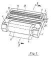
- Figur 1 eine perspektivische Gesamtansicht des Spenders,
- Figur 2 einen Schnitt gemäß der Linie 11-11 in Figur 1 und
- Figur 3 einen vergrößerten Ausschnitt nach 111 in Figur 2.
- Der Spender setzt sich im wesentlichen aus einem Gehäuse 1, einer Abdeckung 2 mit Schneidschiebern 3 und einer in Schräglagerungen 4 gehaltenen Lagerachse 5 zur Aufnahme einer Papierfließrolle 6 zusammen.
- Das Gehäuse 1 gliedert sich in zwei Aufnahmefächer 7, die durch eine Rückwand 8 und zwei an dieser angeformte Auflageplatten 9 gebildet sind und in zwei beidseitig nach unten ragende Haltewangen 10 für die Aufnahme der Lagerachse 5.
- Die Auflageplatten 9 setzen sich nach vorne in einer dazu rechtwinklig stehenden Auflageschnittleiste 11 fort. Die Auflageschnittleisten 11 durchdringen in öffnungen 12 die Abdeckung 2. Zwischen der Abdeckung 2 und der Auflageschnittleiste bleibt am oberen Rand 13 ein Durchlassschlitz 14 für die Rolle.
- Auf der Auflageplatte 9 ist eine Querleiste 15, die mit einer weiteren Leiste 16 auf der Abdeckung 2 ein Labyrinth bildet, vorgesehen. Weiter dient die Querleiste 15 als Stop für die Rolle 17.
- Die Auflageschnittleiste ist wiederum mit einer querverlaufenden Griffleiste 18 sowie einer ebenfalls quer verlaufenden Griffmulde 19 versehen. Mit 20 ist der Verlauf des Rollenendes gekennzeichnet. Beim Schneidvorgang wird das Rollenende 20 durch Andrückrollen 21 im Schneidschieber 3 gegen entsprechende Laufflächen 22 auf der Auflageschnittleiste 11 gedrückt und damit gespannt, während ein Messer 23 in eine Messerführung 24 eintaucht und die Rolle trennt.
- Die Abdeckung 2 ist weiter mit einem Führungsschlitz 25, zur Aufnahme des Schneidschiebers 3 versehen. Auf der Rückseite der Abdeckung geht dieser Führungsschlitz 25 in eine im Querschnitt L-förmige Leiste 26 über. Die Abdeckung 2 ist kastenförmig ausgebildet und überdeckt das Gehäuse 1. Sie wird beidseitig über am Gehäuse angeformte Schnapphalterungen 27 gehalten.
- Die L-förmige Leiste 26 dient als Führung für den Haltebolzen 28 des Schneidschiebers 3. An den Haltebolzen 28 ist eine Andrückfeder 29 angeformt, die das Messer 23 selbsttätig in die Messerführung 24 drückt.
Claims (6)
Priority Applications (6)
| Application Number | Priority Date | Filing Date | Title |
|---|---|---|---|
| EP86115138A EP0265552B1 (de) | 1986-10-31 | 1986-10-31 | Nachfüllbarer Spender für Papier- und/oder Folienrollen |
| DE8686115138T DE3668310D1 (de) | 1986-10-31 | 1986-10-31 | Nachfuellbarer spender fuer papier- und/oder folienrollen. |
| AT86115138T ATE49576T1 (de) | 1986-10-31 | 1986-10-31 | Nachfuellbarer spender fuer papier- und/oder folienrollen. |
| JP62271977A JPH0741572B2 (ja) | 1986-10-31 | 1987-10-29 | 紙巻体および/またはシート巻体のための再補充可能なディスペンサー |
| ES8703109A ES2005429A6 (es) | 1986-10-31 | 1987-10-30 | Expendedor rellenable para rollos de papel yno laminas. |
| US07/116,007 US4762042A (en) | 1986-10-31 | 1987-10-30 | Refillable dispenser for rolls of paper or foil |
Applications Claiming Priority (1)
| Application Number | Priority Date | Filing Date | Title |
|---|---|---|---|
| EP86115138A EP0265552B1 (de) | 1986-10-31 | 1986-10-31 | Nachfüllbarer Spender für Papier- und/oder Folienrollen |
Publications (2)
| Publication Number | Publication Date |
|---|---|
| EP0265552A1 EP0265552A1 (de) | 1988-05-04 |
| EP0265552B1 true EP0265552B1 (de) | 1990-01-17 |
Family
ID=8195551
Family Applications (1)
| Application Number | Title | Priority Date | Filing Date |
|---|---|---|---|
| EP86115138A Expired - Lifetime EP0265552B1 (de) | 1986-10-31 | 1986-10-31 | Nachfüllbarer Spender für Papier- und/oder Folienrollen |
Country Status (6)
| Country | Link |
|---|---|
| US (1) | US4762042A (de) |
| EP (1) | EP0265552B1 (de) |
| JP (1) | JPH0741572B2 (de) |
| AT (1) | ATE49576T1 (de) |
| DE (1) | DE3668310D1 (de) |
| ES (1) | ES2005429A6 (de) |
Cited By (2)
| Publication number | Priority date | Publication date | Assignee | Title |
|---|---|---|---|---|
| EP1184319A2 (de) | 2000-07-08 | 2002-03-06 | LEIFHEIT Aktiengesellschaft | Gerät zum Abtrennen von Bahnen aus Papier und/oder Folie von einer Papier- bzw. Folienrolle |
| DE10355901B4 (de) * | 2003-11-29 | 2013-07-25 | Leifheit Ag | Nachfüllbarer Spender für Papier- und/oder Folienrollen |
Families Citing this family (25)
| Publication number | Priority date | Publication date | Assignee | Title |
|---|---|---|---|---|
| DE3823335C2 (de) * | 1988-07-09 | 1994-03-24 | Wulf & Co Emsa Werk | Vorrichtung zur Aufnahme einer Folienrolle und zum Abschneiden von Folien-Teilstücken |
| EP0378717A1 (de) * | 1989-01-17 | 1990-07-25 | LEIFHEIT Aktiengesellschaft | Nachfüllbarer Spender |
| DE8902353U1 (de) * | 1989-02-28 | 1989-05-24 | Hörnlein, Reinhard, 3450 Holzminden | Aufnahme- und Abschneidvorrichtung für Folienrollen, Papierrollen o.dgl. |
| ES2035477T3 (es) * | 1989-08-16 | 1993-04-16 | Leifheit Aktiengesellschaft | Distribuidor recargable. |
| US5129565A (en) * | 1991-01-22 | 1992-07-14 | Miller Joseph W | Refillable sheet material dispenser |
| DE9103606U1 (de) * | 1991-03-23 | 1991-06-27 | Hörnlein, Reinhard, 3450 Holzminden | Vorrichtung zum Schneiden von Papier-, Alu- oder Klarsichtfolien |
| BR7201950U (pt) * | 1992-11-20 | 1993-04-20 | Purimax Ind Comercio Ltda | Disposicao em porto-rolos |
| US5292046A (en) * | 1992-11-23 | 1994-03-08 | Allen Reed Company, Incorporated | Roll film dispenser |
| USD347345S (en) | 1992-11-23 | 1994-05-31 | Allen Reed Company, Incorporated | Roll film dispenser |
| DE9312389U1 (de) * | 1993-08-14 | 1993-10-21 | Hp Haushaltprodukte Gmbh, 56410 Montabaur | Nachfüllbarer Spender für Papier- und Folienrollen |
| DE9318632U1 (de) * | 1993-12-06 | 1995-04-06 | Emsa-Werke Wulf GmbH & Co, 48282 Emsdetten | Vorrichtung zum Aufnehmen von Folienrollen |
| JPH0857797A (ja) * | 1994-08-18 | 1996-03-05 | Onishi Raito Kogyosho:Kk | シート材の切断装置 |
| US5772094A (en) * | 1995-10-24 | 1998-06-30 | Allen-Reed Company, Inc. | Cutting blade |
| DE19629795C2 (de) * | 1996-07-24 | 2003-01-30 | Freudenberg Carl Kg | Spender für elastisches Flächenmaterial |
| USD396978S (en) | 1997-04-23 | 1998-08-18 | Allen-Reed Company, Inc. | Roll film dispenser |
| US7080765B2 (en) * | 2001-10-15 | 2006-07-25 | Joseph W Miller | Multiple roll and boxed goods dispenser |
| US6772666B2 (en) * | 2001-11-07 | 2004-08-10 | Tilia International, Inc. | Bag stand |
| US6910579B2 (en) | 2002-05-28 | 2005-06-28 | Georgia-Pacific Corporation | Refillable flexible sheet dispenser |
| US7000520B2 (en) * | 2002-06-12 | 2006-02-21 | Reynolds Metals Company | Roll supporting slide cutter assembly incorporating a traversable cutter tab and in particular capable of being supported within a carton enclosure associated with a wrap material roll |
| US20070193917A1 (en) * | 2006-02-15 | 2007-08-23 | Munoz Maria D | Gift wrap organizer and dispenser |
| US20120074161A1 (en) * | 2010-09-28 | 2012-03-29 | Sotiria Efthimiadis | Dispenser for roll materials |
| RO129539B1 (ro) * | 2014-02-19 | 2017-01-30 | Radu Filipescu | Dispozitiv de tăiere folie |
| CN104960965B (zh) * | 2015-06-27 | 2017-02-01 | 绍兴两溪茶厂 | 一种可调节分切装置 |
| CN107298340B (zh) * | 2017-08-28 | 2021-06-18 | 南通锦发电缆有限公司 | 一种电缆高防护性收卷装置 |
| USD980018S1 (en) * | 2022-06-17 | 2023-03-07 | Linjun Huang | Dispenser |
Family Cites Families (7)
| Publication number | Priority date | Publication date | Assignee | Title |
|---|---|---|---|---|
| US3142217A (en) * | 1961-05-12 | 1964-07-28 | Clarence E Busse | Cutter for dispenser of aluminum foil and like material |
| US3222972A (en) * | 1963-04-08 | 1965-12-14 | Reynolds Metals Co | Dispenser for coiled sheet material |
| US3236427A (en) * | 1963-06-28 | 1966-02-22 | Reynolds Metals Co | Dispenser for coiled sheet material |
| US3240093A (en) * | 1964-01-14 | 1966-03-15 | Safeguard Corp | Continuous sheet dispenser and cutter |
| DE1946081C3 (de) * | 1969-09-11 | 1973-09-27 | Kurt Dr.Med. 7000 Stuttgart Walker | Abgabebehälter für eine insbesondere der Analhygiene dienende, angefeuchtete Stoffbahn |
| DE2849457C2 (de) * | 1978-11-15 | 1983-03-10 | Leifheit International Günter Leifheit GmbH, 5408 Nassau | Vorrichtung zur Aufnahme von mindestens einer Papier-, Vlies-, Folienrolle o.dgl. |
| DE3525321A1 (de) * | 1985-02-23 | 1986-08-28 | Emsa-Werke Wulf GmbH & Co, 4407 Emsdetten | Vorrichtung zur aufnahme einer folienrolle und zur entnahme abgeschnittener teilstuecke der folie |
-
1986
- 1986-10-31 EP EP86115138A patent/EP0265552B1/de not_active Expired - Lifetime
- 1986-10-31 AT AT86115138T patent/ATE49576T1/de not_active IP Right Cessation
- 1986-10-31 DE DE8686115138T patent/DE3668310D1/de not_active Expired - Lifetime
-
1987
- 1987-10-29 JP JP62271977A patent/JPH0741572B2/ja not_active Expired - Fee Related
- 1987-10-30 US US07/116,007 patent/US4762042A/en not_active Expired - Lifetime
- 1987-10-30 ES ES8703109A patent/ES2005429A6/es not_active Expired
Cited By (2)
| Publication number | Priority date | Publication date | Assignee | Title |
|---|---|---|---|---|
| EP1184319A2 (de) | 2000-07-08 | 2002-03-06 | LEIFHEIT Aktiengesellschaft | Gerät zum Abtrennen von Bahnen aus Papier und/oder Folie von einer Papier- bzw. Folienrolle |
| DE10355901B4 (de) * | 2003-11-29 | 2013-07-25 | Leifheit Ag | Nachfüllbarer Spender für Papier- und/oder Folienrollen |
Also Published As
| Publication number | Publication date |
|---|---|
| JPS63212493A (ja) | 1988-09-05 |
| JPH0741572B2 (ja) | 1995-05-10 |
| ATE49576T1 (de) | 1990-02-15 |
| DE3668310D1 (de) | 1990-02-22 |
| ES2005429A6 (es) | 1989-03-01 |
| US4762042A (en) | 1988-08-09 |
| EP0265552A1 (de) | 1988-05-04 |
Similar Documents
| Publication | Publication Date | Title |
|---|---|---|
| EP0265552B1 (de) | Nachfüllbarer Spender für Papier- und/oder Folienrollen | |
| DE202005004916U1 (de) | Schneidgerät | |
| DE3301889A1 (de) | Vorrichtung zur abgabe von bahnfoermigem material | |
| DE69004995T2 (de) | Schnittkantenschutz. | |
| EP2799379A1 (de) | Abgabegerät | |
| EP1553035B1 (de) | Vorrichtung zur Aufbewahrung und Abgabe einer Abdeckfolie | |
| DE29602579U1 (de) | Vorrichtung zum Beölen der mehreren Messer einer Brotschneidmaschine | |
| DE60025346T2 (de) | Bandspender | |
| EP0413039B1 (de) | Nachfüllbarer Spender | |
| DE8715936U1 (de) | Nachfüllbarer Spender für Papier- und/oder Folienrollen | |
| DE1946081C3 (de) | Abgabebehälter für eine insbesondere der Analhygiene dienende, angefeuchtete Stoffbahn | |
| DE10355901B4 (de) | Nachfüllbarer Spender für Papier- und/oder Folienrollen | |
| EP1493540B1 (de) | Papierschneidgerät | |
| EP0378717A1 (de) | Nachfüllbarer Spender | |
| DE2602168A1 (de) | Blatt- oder streifenspender | |
| DE3203448A1 (de) | Vorrichtung zum einziehen von buerstendichtstreifen in nuten von fenster- oder tuerprofilleisten | |
| DE19727198C2 (de) | Kleisterauftragsgerät für Tapetenbahnen | |
| DE20307241U1 (de) | Schneidgerät | |
| DE9303314U1 (de) | Nachfüllbarer Spender | |
| DE1913427A1 (de) | Zeichenanlage | |
| EP1184319B1 (de) | Gerät zum Abtrennen von Bahnen aus Papier und/oder Folie von einer Papier- bzw. Folienrolle | |
| DE602004001178T2 (de) | Abreissvorrichtung mit Schutzeinrichtung | |
| DE2525861A1 (de) | Spendegeraet fuer folien- bzw. papierabschnitte | |
| DE29819604U1 (de) | Vorrichtung zum dosierten Abgeben von folienartigem Material | |
| DE29913045U1 (de) | Klingenspender |
Legal Events
| Date | Code | Title | Description |
|---|---|---|---|
| PUAI | Public reference made under article 153(3) epc to a published international application that has entered the european phase |
Free format text: ORIGINAL CODE: 0009012 |
|
| 17P | Request for examination filed |
Effective date: 19861031 |
|
| AK | Designated contracting states |
Kind code of ref document: A1 Designated state(s): AT BE CH DE FR GB IT LI LU NL SE |
|
| RBV | Designated contracting states (corrected) |
Designated state(s): AT BE CH DE FR GB IT LI NL SE |
|
| 17Q | First examination report despatched |
Effective date: 19880722 |
|
| ITF | It: translation for a ep patent filed | ||
| GRAA | (expected) grant |
Free format text: ORIGINAL CODE: 0009210 |
|
| AK | Designated contracting states |
Kind code of ref document: B1 Designated state(s): AT BE CH DE FR GB IT LI NL SE |
|
| REF | Corresponds to: |
Ref document number: 49576 Country of ref document: AT Date of ref document: 19900215 Kind code of ref document: T |
|
| GBT | Gb: translation of ep patent filed (gb section 77(6)(a)/1977) | ||
| REF | Corresponds to: |
Ref document number: 3668310 Country of ref document: DE Date of ref document: 19900222 |
|
| ET | Fr: translation filed | ||
| PLBE | No opposition filed within time limit |
Free format text: ORIGINAL CODE: 0009261 |
|
| STAA | Information on the status of an ep patent application or granted ep patent |
Free format text: STATUS: NO OPPOSITION FILED WITHIN TIME LIMIT |
|
| 26N | No opposition filed | ||
| ITTA | It: last paid annual fee | ||
| EAL | Se: european patent in force in sweden |
Ref document number: 86115138.9 |
|
| PGFP | Annual fee paid to national office [announced via postgrant information from national office to epo] |
Ref country code: SE Payment date: 20000906 Year of fee payment: 15 |
|
| PG25 | Lapsed in a contracting state [announced via postgrant information from national office to epo] |
Ref country code: SE Free format text: LAPSE BECAUSE OF NON-PAYMENT OF DUE FEES Effective date: 20011101 |
|
| REG | Reference to a national code |
Ref country code: GB Ref legal event code: IF02 |
|
| EUG | Se: european patent has lapsed |
Ref document number: 86115138.9 |
|
| PGFP | Annual fee paid to national office [announced via postgrant information from national office to epo] |
Ref country code: AT Payment date: 20050914 Year of fee payment: 20 Ref country code: GB Payment date: 20050914 Year of fee payment: 20 |
|
| PGFP | Annual fee paid to national office [announced via postgrant information from national office to epo] |
Ref country code: NL Payment date: 20050916 Year of fee payment: 20 |
|
| PGFP | Annual fee paid to national office [announced via postgrant information from national office to epo] |
Ref country code: FR Payment date: 20051006 Year of fee payment: 20 |
|
| PGFP | Annual fee paid to national office [announced via postgrant information from national office to epo] |
Ref country code: IT Payment date: 20051013 Year of fee payment: 20 |
|
| PGFP | Annual fee paid to national office [announced via postgrant information from national office to epo] |
Ref country code: DE Payment date: 20051031 Year of fee payment: 20 |
|
| PGFP | Annual fee paid to national office [announced via postgrant information from national office to epo] |
Ref country code: BE Payment date: 20051104 Year of fee payment: 20 |
|
| REG | Reference to a national code |
Ref country code: GB Ref legal event code: PE20 |
|
| PGFP | Annual fee paid to national office [announced via postgrant information from national office to epo] |
Ref country code: CH Payment date: 20051216 Year of fee payment: 20 |
|
| PG25 | Lapsed in a contracting state [announced via postgrant information from national office to epo] |
Ref country code: GB Free format text: LAPSE BECAUSE OF EXPIRATION OF PROTECTION Effective date: 20061030 |
|
| PG25 | Lapsed in a contracting state [announced via postgrant information from national office to epo] |
Ref country code: NL Free format text: LAPSE BECAUSE OF EXPIRATION OF PROTECTION Effective date: 20061031 |
|
| REG | Reference to a national code |
Ref country code: CH Ref legal event code: PL |
|
| NLV7 | Nl: ceased due to reaching the maximum lifetime of a patent |
Effective date: 20061031 |
|
| BE20 | Be: patent expired |
Owner name: *LEIFHEIT A.G. Effective date: 20061031 |