EP0265564A1 - Vorrichtung, um eine fertig montierte Jalousie auf eine gegebene Länge zurückzuschneiden - Google Patents
Vorrichtung, um eine fertig montierte Jalousie auf eine gegebene Länge zurückzuschneiden Download PDFInfo
- Publication number
- EP0265564A1 EP0265564A1 EP86308485A EP86308485A EP0265564A1 EP 0265564 A1 EP0265564 A1 EP 0265564A1 EP 86308485 A EP86308485 A EP 86308485A EP 86308485 A EP86308485 A EP 86308485A EP 0265564 A1 EP0265564 A1 EP 0265564A1
- Authority
- EP
- European Patent Office
- Prior art keywords
- slat
- trimming
- blind
- fingers
- slats
- Prior art date
- Legal status (The legal status is an assumption and is not a legal conclusion. Google has not performed a legal analysis and makes no representation as to the accuracy of the status listed.)
- Withdrawn
Links
- 238000009966 trimming Methods 0.000 claims abstract description 66
- 230000007246 mechanism Effects 0.000 description 5
- 238000013016 damping Methods 0.000 description 1
- 230000006870 function Effects 0.000 description 1
- 230000005019 pattern of movement Effects 0.000 description 1
- 230000000284 resting effect Effects 0.000 description 1
- 230000000630 rising effect Effects 0.000 description 1
- 238000010008 shearing Methods 0.000 description 1
- 238000009987 spinning Methods 0.000 description 1
Images



Classifications
-
- E—FIXED CONSTRUCTIONS
- E06—DOORS, WINDOWS, SHUTTERS, OR ROLLER BLINDS IN GENERAL; LADDERS
- E06B—FIXED OR MOVABLE CLOSURES FOR OPENINGS IN BUILDINGS, VEHICLES, FENCES OR LIKE ENCLOSURES IN GENERAL, e.g. DOORS, WINDOWS, BLINDS, GATES
- E06B9/00—Screening or protective devices for wall or similar openings, with or without operating or securing mechanisms; Closures of similar construction
- E06B9/24—Screens or other constructions affording protection against light, especially against sunshine; Similar screens for privacy or appearance; Slat blinds
- E06B9/26—Lamellar or like blinds, e.g. venetian blinds
- E06B9/266—Devices or accessories for making or mounting lamellar blinds or parts thereof
-
- B—PERFORMING OPERATIONS; TRANSPORTING
- B23—MACHINE TOOLS; METAL-WORKING NOT OTHERWISE PROVIDED FOR
- B23D—PLANING; SLOTTING; SHEARING; BROACHING; SAWING; FILING; SCRAPING; LIKE OPERATIONS FOR WORKING METAL BY REMOVING MATERIAL, NOT OTHERWISE PROVIDED FOR
- B23D47/00—Sawing machines or sawing devices working with circular saw blades, characterised only by constructional features of particular parts
- B23D47/08—Sawing machines or sawing devices working with circular saw blades, characterised only by constructional features of particular parts of devices for bringing the circular saw blade to the workpiece or removing same therefrom
-
- B—PERFORMING OPERATIONS; TRANSPORTING
- B26—HAND CUTTING TOOLS; CUTTING; SEVERING
- B26D—CUTTING; DETAILS COMMON TO MACHINES FOR PERFORATING, PUNCHING, CUTTING-OUT, STAMPING-OUT OR SEVERING
- B26D7/00—Details of apparatus for cutting, cutting-out, stamping-out, punching, perforating, or severing by means other than cutting
Definitions
- Venetian blinds are comprised of a head rail, a bottom rail and slats supported by cross members of ladder tapes fixed at their ends to the head and bottom rails.
- Cords fixed to the bottom rail and passing through slots in the slats are passed over pulleys in the head rail. By pulling on the cords the slats are gathered together as the bottom rail is lifted to the head rail.
- venetian blinds are made up in quantity for supply to persons with standard width windows. If a person requires a venetian blind for a non-standard width window it has to be made as a special order with the head and bottom rails and slats being made to the correct lengths and then assembled with ladder tapes and cords. This prevents the sale of non-standard width venetian blinds in retail stores.
- blind length means blind width.
- This invention has been made so that a retail store which holds a range of assembled venetian blinds of different lengths can trim unwanted length from a blind to provide a customer's length requirement.
- a possible range would provide a 150mm difference between blind lengths with the cord pulleys and ladder tapes located no closer than 150 mms from each end of the blind. If the maximum 150mms was cut from a blind, say 75mms from each end of the blind, then there would still be an acceptable distance of 75mms between the ends of the blind and the ladder tapes.
- the invention can be said to comprise a length trimming machine for an assembled venetian blind comprising at least a head rail and slats supported in ladder tapes fixed to the head rail; the machine comprising a base member, a number of blind supports upstanding from the base member, retractable support fingers on the blind supports to mount the head rail of a venetian blind in a generally horizontal plane with at least the slats adjacent the head rail in their open position, a slat lifter mounted for vertical sliding movement on each support, retractable lifting fingers on each slat lifter, slat lifter moving means to raise the slat lifters to an elevation where the lifting fingers are above the support fingers and to lower the slat lifters to a rest position where the lifting fingers are a predetermined distance below the support fingers, a slat trimming assembly including a pair of slat trimming blades, means to move the trimming blades one relative to the other, and means to cyclically move the slat trimming assembly vertically into horizontal alignment with selected
- the machine as illustrated comprises a base having a bed 1 and two supporting legs 2 and 3.
- the leg 2 houses power and control mechanisms for the machine to enable the operation of the machine in the manner to be described.
- Mounted on bed 1 there are upstanding supports 4.5.6 and 7.
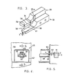
- the supports have foot portions 10 and, as will be best seen in Fig.2, the foot portions 10 have extended lugs 10a to engage in the groove 11 in the upstanding back rail 12 of the bed and forwardly extending lugs 10b over which there is placed damping blocks 13 with clamping screws 14 which can be screwed into threaded holes of a row of holes 15 in the bed 1 to position the supports where required along the length of the bed.
- the supports 4 to 7 are respectively comprised of two legs 4a and 4b, 5a and 5b, 6a and 6b and 7a and 7b.
- the legs are provided with elongated slots 8, to be seen on the leg 5b, from which parts to be described have been removed to facilitate the understanding of the invention.
- Inset into each of the legs there is a pivotally mounted finger 16 to support the top rail 17 of a blind to be trimmed to length, see Fig.2, and which will support the slats of the blind after they are trimmed and are raised onto the fingers 16. as will be understood from the following description.
- the fingers 16 are made to be gravitationally biassed to the lowered support position shown, and so as to deflect upwardly when slats are moved upwardly past the fingers, as will be understood from the following description.
- each support (but not shown on the support 5) there is a lifter 18 comprised of two U shaped plates 19 and 20 joined at 21.
- the lifters 18 have guide pins 22 engaged in the slots 8.
- the fingers 23 will deflect to allow a slat to pass by the fingers as the lifters are lowered relative to the slats.
- each lifter 18 Extending to the rear of each lifter 18 and fixed thereto there is a roller 24 which bears on a bar 25 connected by links 26 to the bed 1.
- the bar 25 is connected to the piston rod a hydraulic or air operated cylinder 27 and it is clear that as the piston is moved outwardly in the cylinder 27 the links 26 will raise the bar 25 which will raise the rollers 24 and the lifters connected thereto.
- a movable slat trimming assembly 28 including a scissor-like blade combination with a non-moving blade 29 fixed to a bearing block 30 having an arm 31 connected to a trimming assembly moving mechanism in the leg 2.
- a moving blade 32 on a column 34 slidable in the bearing block 30.
- the non-moving blade 29 has a guide rib 29a which is engaged in a correspondingly shaped groove 32a in the blade 32.
- the cutting part of the blade 29 comprises a cutting edge 35 with rounded corners 36 and the blade 32 has a similarly shaped notch 37 with rounded corners 38. This provides the required end shape for trimmed slats.
- top face 39 of the blade 32 is angled at 2 degrees (which angle can be varied) to the underface of the blade 29 to give a shearing scissor-like action as the cutting edges 35-36 pass through the notch 37-38 as the blade 32 moves up and down relative to the blade 29.
- the blind head rail 17 is positioned on the fingers 16 and the blind slats are allowed to drop freely between the support legs 4a & b, 5a & b, 6a & b and 7a & b with at least the first slat 39, the second slat 40, the third slat 41 and the fourth slat 42 suspended below the head rail 17 with the normal spacing therebetween.
- the trimming position on the blind slats is aligned with the trimming assembly by sliding the blind head rail 17 on the fingers 16.
- the trimming assembly is in a rest position at the elevation of the slat 39 and to the rear of the slats, see Fig.1 and Fig.6.
- the trimming assembly is caused to follow a pattern of movements as now to be described and then return to the rest position.
- the tops of the fingers 23 are at a distance A from the tops of the fingers 16 and this places the tops of the fingers 23 between slats 40 and 41 and closer to slat 41.
- the ladder tape is of the type comprising a pair of robust vertical cords 43 joined by fine slat cords 44 and the slats rest upon the top of the slat cords 44.
- the trimming assembly with the blades separated moves forwardly from the rest position aligned with the slat 39 and by means of the mechanism within the leg 2 trims the unwanted length from the end of the slat 39 by upward movement of the blade 32.
- the blade 32 is then lowered and the trimming assembly is moved back to the rest position.
- the trimming assembly is then lowered to its second position (Fig.7) where the blades 29-32 are aligned with the slat 40.
- the trimming assembly is moved forwardly and the end of the slat 40 is trimmed and the trimming assembly moves back to the second position.
- the trimming assembly is then lowered again to take up its wait position, see Fig.8, where the wait position is shown as A from the tops of the fingers 16.
- the trimming assembly blades and the fingers 23 from the tops of the fingers 16 will be given specific values in mms. It is to be understood that these values can be different for different types of blind but they are representative for one type of blind and serve to illustrate the theory behind the invention.
- the piston in the cylinder 27 is now extended to raise the bar 25 and the lifters and the lifter fingers 23.
- the slats 39 and 40 are gathered together by the rising fingers 23 and are raised to an elevation above the fingers 16 which retract to allow the slats 39 and 40 to pass.
- the head rail 17 is raised by the slats. After the slat 40 passes the fingers 16 they gravitationally return to the extended position.
- the piston is then withdrawn into the cylinder 27, the bar 25 lowers the lifters and the slats 39-40 with the head 17 resting thereon are lowered onto the fingers 16 as can be seen in Fig.9.
- the mechanism controlling the operation of the machine functions will detect the retraction of the piston in the cylinder 27 and the lowering of the lifters to the position where the fingers 23 are below the slat 41.
- the trimming assembly will then be advanced, the slat trimming operation and the slat lifting operation as described above will be repeated again and again until all of the slats have been cut.
- the number of trimming sequences can be contolled manually or by a memory controller set to the number of cuts required, related to the number of slats in the blind. After all cuts have been completed the trimming assembly will automatically rise to the rest position where it will remain until the operating sequence is initiated by the operator when the other end of the blind is set up for trimming or another blind is set up for trimming.
- the head rail and bottom rails need to be trimmed to length.
- the trimming of the head and bottom rails is preformed manually or by an attachment on the machine.
- the trimming is preformed in a trimming attachment 45 on the machine leg 2, see Fig.1.
- a table 46 at the front of the machine aligned with the trimming attachment 45 but at an elevation below the trimming attachment 45.
- Fig.4 which is a view in the direction of the arrow 4 of Fig.1, the trimming attachment includes a safety cover 47 and a channel shaped support 48 within the cover with arms 49 fixed to the face 50 of the machine leg 2.
- the support 48 is positioned relative to a cutter assembly comprised of a rotatable holder 51 which rotates about the axis X-X and in the holder 51 there is rotatably supported a shaft 52 which is rotatable about the axis Y-Y and a saw blade 53 is fixed to the shaft 52.
- a suitable drive means is provided for the cutter assmebly within the machine leg 2 to give fast rotation of the cutter shaft 52 with the blade 53 and slow rotation of the holder 51.
- the holder 51 after each revolution comes to rest as shown in Fig.4 with the blade 53 at the position shown.
- an adjustable stop 55 on the table 46 Prior to performing a trimming operation an adjustable stop 55 on the table 46 is positioned a correct distance from the blade 53.
- the blind is placed on the table 46 and the end of the blind head rail 17 (or its bottom rail) to be trimmed off to alignment with the trimmed ends of the slats is placed in the support 48.
- the ends of the slats at the other end of blind are pushed against the stop 55. This will place the blade 53 at the correct cutting position relative to the rail end to be cut and the blind is held firmly in this position whilst the head rail end is trimmed.
- Fig.4 shows that under such conditions the outer edge of the rapidly spinning blade 53 will follow a path which will cut through the sides and bottom of a head rail lying in the support 48 and sever the part of the rail projecting beyond the blade 53.
- the cut-off portion will discharge down the chute 54 shown in Fig.1 In this way the head and/or bottom rail can be made the same length as the slats or longer or shorter as the operator requires simply by adjusting the position of the stop 55.
- both ends of a blind could be trimmed at the one time.
- the ends of the rails could then be trimmed to length one at a time as described above.
Landscapes
- Engineering & Computer Science (AREA)
- Mechanical Engineering (AREA)
- Structural Engineering (AREA)
- Life Sciences & Earth Sciences (AREA)
- Forests & Forestry (AREA)
- Architecture (AREA)
- Civil Engineering (AREA)
- Blinds (AREA)
Priority Applications (2)
| Application Number | Priority Date | Filing Date | Title |
|---|---|---|---|
| GB08625955A GB2197012A (en) | 1986-10-30 | 1986-10-30 | Producing venetian blinds |
| EP86308485A EP0265564A1 (de) | 1986-10-30 | 1986-10-30 | Vorrichtung, um eine fertig montierte Jalousie auf eine gegebene Länge zurückzuschneiden |
Applications Claiming Priority (1)
| Application Number | Priority Date | Filing Date | Title |
|---|---|---|---|
| EP86308485A EP0265564A1 (de) | 1986-10-30 | 1986-10-30 | Vorrichtung, um eine fertig montierte Jalousie auf eine gegebene Länge zurückzuschneiden |
Publications (1)
| Publication Number | Publication Date |
|---|---|
| EP0265564A1 true EP0265564A1 (de) | 1988-05-04 |
Family
ID=8196197
Family Applications (1)
| Application Number | Title | Priority Date | Filing Date |
|---|---|---|---|
| EP86308485A Withdrawn EP0265564A1 (de) | 1986-10-30 | 1986-10-30 | Vorrichtung, um eine fertig montierte Jalousie auf eine gegebene Länge zurückzuschneiden |
Country Status (2)
| Country | Link |
|---|---|
| EP (1) | EP0265564A1 (de) |
| GB (1) | GB2197012A (de) |
Cited By (20)
| Publication number | Priority date | Publication date | Assignee | Title |
|---|---|---|---|---|
| AU632573B2 (en) * | 1989-04-25 | 1993-01-07 | A/S Chr. Fabers Fabriker | Apparatus for assembling slats of venetian blinds |
| EP0893569A3 (de) * | 1997-07-25 | 1999-06-23 | Newell Window Furnishings, Inc. | Doppelte Schneidvorrichtung für Jalousien |
| US6435066B1 (en) | 1997-12-18 | 2002-08-20 | Springs Window Fashions Division, Inc. | Cutting apparatus for window covering and methods therefor |
| US6604443B2 (en) | 2001-07-23 | 2003-08-12 | Newell Window Furnishings, Inc. | Blind and shade cutting center |
| US6973364B2 (en) | 2003-03-03 | 2005-12-06 | Schwartz David A | Remotely connected blind cutting center |
| US7017459B2 (en) | 1999-07-23 | 2006-03-28 | Shade-O-Matic Limited | Blind cut down machine |
| US7036412B2 (en) | 2003-03-03 | 2006-05-02 | Newell Window Furnishings, Inc. | Blind cutting center with detachable vacuum bag |
| US7059230B2 (en) | 2003-03-03 | 2006-06-13 | Caputo Thomas A | Adjustable blind cutting device |
| US7178439B2 (en) | 2003-03-03 | 2007-02-20 | Newell Window Furnishings, Inc. | Blind cutting center |
| US7810418B2 (en) | 2003-03-03 | 2010-10-12 | Newell Window Furnishings, Inc. | Automatically configurable blind cutting center |
| US7918150B2 (en) | 1999-07-23 | 2011-04-05 | Shade-O-Matic Limited | Blind cut down machine |
| US7987754B2 (en) | 2007-07-31 | 2011-08-02 | Newell Window Furnishings, Inc. | Window covering sizing method and apparatus |
| US8256333B2 (en) | 2007-07-31 | 2012-09-04 | Newell Window Furnishings, Inc. | Window covering sizing method and apparatus |
| US8322260B2 (en) | 2007-07-31 | 2012-12-04 | Newell Window Furnishings, Inc. | Window covering sizing method and apparatus |
| US8479925B2 (en) | 2010-07-19 | 2013-07-09 | Newell Window Furnishings, Inc. | Display system |
| US8499670B2 (en) | 2001-07-23 | 2013-08-06 | Newell Window Furnishings, Inc. | Modular blind cutting center |
| US8839701B2 (en) | 2007-07-31 | 2014-09-23 | Newell Window Furnishings, Inc. | Window covering sizing method and apparatus |
| US9266639B2 (en) | 2010-07-19 | 2016-02-23 | Newell Window Furnishings, Inc. | Blind packaging and methods of cutting window coverings |
| US9427813B2 (en) | 2007-07-31 | 2016-08-30 | Newell Window Furnishing, Inc. | Window covering sizing method and apparatus |
| CN113649644A (zh) * | 2021-07-30 | 2021-11-16 | 刘娜 | 一种建筑板材切割装置 |
Citations (3)
| Publication number | Priority date | Publication date | Assignee | Title |
|---|---|---|---|---|
| DE1602520A1 (de) * | 1966-09-27 | 1970-12-23 | Nilsson Stig Albert | Verfahren und Vorrichtung zum Einfuehren von Jalousielatten in die Tragbaender einer Jalousie |
| US4227305A (en) * | 1979-03-12 | 1980-10-14 | Newman Jerry C | Hand tool for cutting blind strips and the like |
| EP0100154A2 (de) * | 1982-07-23 | 1984-02-08 | Hunter Douglas Industries B.V. | Baueinheit zur Positionierung eines Jalousieleiterbandes und zur Führung der Jalousiestäbe daran |
-
1986
- 1986-10-30 GB GB08625955A patent/GB2197012A/en not_active Withdrawn
- 1986-10-30 EP EP86308485A patent/EP0265564A1/de not_active Withdrawn
Patent Citations (3)
| Publication number | Priority date | Publication date | Assignee | Title |
|---|---|---|---|---|
| DE1602520A1 (de) * | 1966-09-27 | 1970-12-23 | Nilsson Stig Albert | Verfahren und Vorrichtung zum Einfuehren von Jalousielatten in die Tragbaender einer Jalousie |
| US4227305A (en) * | 1979-03-12 | 1980-10-14 | Newman Jerry C | Hand tool for cutting blind strips and the like |
| EP0100154A2 (de) * | 1982-07-23 | 1984-02-08 | Hunter Douglas Industries B.V. | Baueinheit zur Positionierung eines Jalousieleiterbandes und zur Führung der Jalousiestäbe daran |
Cited By (41)
| Publication number | Priority date | Publication date | Assignee | Title |
|---|---|---|---|---|
| AU632573B2 (en) * | 1989-04-25 | 1993-01-07 | A/S Chr. Fabers Fabriker | Apparatus for assembling slats of venetian blinds |
| EP0893569A3 (de) * | 1997-07-25 | 1999-06-23 | Newell Window Furnishings, Inc. | Doppelte Schneidvorrichtung für Jalousien |
| US6167789B1 (en) | 1997-07-25 | 2001-01-02 | Newell Operating Company | Dual mini-blind cutter |
| US6314851B1 (en) | 1997-07-25 | 2001-11-13 | Newell Operating Company | Dual mini-blind cutter |
| US6435066B1 (en) | 1997-12-18 | 2002-08-20 | Springs Window Fashions Division, Inc. | Cutting apparatus for window covering and methods therefor |
| US6681673B1 (en) | 1997-12-18 | 2004-01-27 | Springs Window Fashions Lp | Cutting apparatus for window coverings and methods therefor |
| US6782788B1 (en) | 1997-12-18 | 2004-08-31 | Springs Window Fashions Lp | Cutting blade for a cutting apparatus |
| USRE40605E1 (en) * | 1997-12-18 | 2008-12-16 | Springs Window Fashions, Llc | Cutting apparatus for window coverings and methods therefor |
| US7017459B2 (en) | 1999-07-23 | 2006-03-28 | Shade-O-Matic Limited | Blind cut down machine |
| US7918150B2 (en) | 1999-07-23 | 2011-04-05 | Shade-O-Matic Limited | Blind cut down machine |
| US7681480B2 (en) | 2001-07-23 | 2010-03-23 | Newell Window Furnishings, Inc. | Blind and shade cutting center for cutting two different window covering products |
| US7007576B2 (en) | 2001-07-23 | 2006-03-07 | Newell Window Furnishings, Inc. | Method of positioning a window covering in a sizing mechanism |
| US7040205B2 (en) | 2001-07-23 | 2006-05-09 | Newell Window Furnishings, Inc | Blind and shade cutting center with movable cutting station |
| US8286538B2 (en) | 2001-07-23 | 2012-10-16 | Newell Window Furnishings, Inc. | Blind and shade cutting center for cutting two different window covering products |
| US7069832B2 (en) | 2001-07-23 | 2006-07-04 | Newell Window Furnishings, Inc. | Blind and shade cutting center with movable locator |
| US7069833B2 (en) | 2001-07-23 | 2006-07-04 | Newell Window Furnishings, Inc. | Moveable blind and shade cutting center |
| US7100485B2 (en) | 2001-07-23 | 2006-09-05 | Newell Window Furnishings, Inc. | Blind and shade cutting center |
| US7104175B2 (en) | 2001-07-23 | 2006-09-12 | Newell Window Furnishings, Inc. | Blind and shade cutting center with center locating system |
| US8161857B2 (en) | 2001-07-23 | 2012-04-24 | Newell Window Furnishings, Inc. | Blind and shade cutting center for cutting two different window covering products |
| US8499670B2 (en) | 2001-07-23 | 2013-08-06 | Newell Window Furnishings, Inc. | Modular blind cutting center |
| US6604443B2 (en) | 2001-07-23 | 2003-08-12 | Newell Window Furnishings, Inc. | Blind and shade cutting center |
| US7810418B2 (en) | 2003-03-03 | 2010-10-12 | Newell Window Furnishings, Inc. | Automatically configurable blind cutting center |
| US6973364B2 (en) | 2003-03-03 | 2005-12-06 | Schwartz David A | Remotely connected blind cutting center |
| US10792739B2 (en) | 2003-03-03 | 2020-10-06 | Hunter Douglas Industries Switzerland Gmbh | Automatically configurable blind cutting center |
| US7178439B2 (en) | 2003-03-03 | 2007-02-20 | Newell Window Furnishings, Inc. | Blind cutting center |
| US7036412B2 (en) | 2003-03-03 | 2006-05-02 | Newell Window Furnishings, Inc. | Blind cutting center with detachable vacuum bag |
| US7059230B2 (en) | 2003-03-03 | 2006-06-13 | Caputo Thomas A | Adjustable blind cutting device |
| US8256333B2 (en) | 2007-07-31 | 2012-09-04 | Newell Window Furnishings, Inc. | Window covering sizing method and apparatus |
| US9440368B2 (en) | 2007-07-31 | 2016-09-13 | Newell Window Furnishings, Inc. | Window covering sizing method and apparatus |
| US8322260B2 (en) | 2007-07-31 | 2012-12-04 | Newell Window Furnishings, Inc. | Window covering sizing method and apparatus |
| US8631732B1 (en) | 2007-07-31 | 2014-01-21 | Newell Window Furnishings, Inc. | Window covering sizing method and apparatus |
| US8839701B2 (en) | 2007-07-31 | 2014-09-23 | Newell Window Furnishings, Inc. | Window covering sizing method and apparatus |
| US11872716B2 (en) | 2007-07-31 | 2024-01-16 | Hunter Douglas Industries Switzerland Gmbh | Window covering sizing method and apparatus |
| US9427813B2 (en) | 2007-07-31 | 2016-08-30 | Newell Window Furnishing, Inc. | Window covering sizing method and apparatus |
| US7987754B2 (en) | 2007-07-31 | 2011-08-02 | Newell Window Furnishings, Inc. | Window covering sizing method and apparatus |
| US10786921B2 (en) | 2007-07-31 | 2020-09-29 | Hunter Douglas Industries Switzerland Gmbh | Window covering sizing method and apparatus |
| US10450129B2 (en) | 2010-07-19 | 2019-10-22 | Levolor, Inc. | Blind packaging and methods of cutting window coverings |
| US8479925B2 (en) | 2010-07-19 | 2013-07-09 | Newell Window Furnishings, Inc. | Display system |
| US11312566B2 (en) | 2010-07-19 | 2022-04-26 | Hunter Douglas Industries Switzerland Gmbh | Blind packaging and methods of cutting window coverings |
| US9266639B2 (en) | 2010-07-19 | 2016-02-23 | Newell Window Furnishings, Inc. | Blind packaging and methods of cutting window coverings |
| CN113649644A (zh) * | 2021-07-30 | 2021-11-16 | 刘娜 | 一种建筑板材切割装置 |
Also Published As
| Publication number | Publication date |
|---|---|
| GB8625955D0 (en) | 1986-12-03 |
| GB2197012A (en) | 1988-05-11 |
Similar Documents
| Publication | Publication Date | Title |
|---|---|---|
| EP0265564A1 (de) | Vorrichtung, um eine fertig montierte Jalousie auf eine gegebene Länge zurückzuschneiden | |
| US20090107313A1 (en) | Assembled blind cutting machine | |
| US7040205B2 (en) | Blind and shade cutting center with movable cutting station | |
| EP0273535A1 (de) | Vorrichtung, um eine fertig montierte Jalousie auf eine gegebene Länge zurückzuschneiden | |
| US6003217A (en) | Size-in-store pleated shade and method and apparatus of sizing | |
| US8505422B2 (en) | Cutting machine for blinds | |
| US20110088524A1 (en) | Automatically Configurable Blind Cutting Center | |
| EP1078143B1 (de) | Vorrichtung für die herstellung von lamellen | |
| CA2460097C (en) | Adjustable blind cutting device | |
| EP0019292B1 (de) | Sägemaschinen | |
| GB2258686A (en) | Pleated shade | |
| JPS63125794A (ja) | 組立て済みベネツチアンブラインドを所定の長さにトリムする装置 | |
| CN216193565U (zh) | 一种遮光植绒窗帘布的裁剪装置 | |
| AU2007231774B2 (en) | Assembled Blind Cutting Machine | |
| CN111020823B (zh) | 一种织布机的废边裁剪装置 | |
| JPH0570163A (ja) | ガラス板の折り割り機械 | |
| CN221473686U (zh) | 一种货架加工用裁边装置 | |
| CA2607925A1 (en) | Assembled blind cutting machine | |
| CA1143254A (en) | Sawing machine | |
| JPH07205086A (ja) | ギロチン式切断機 | |
| JPS6471990A (en) | Device for trimming assembled venetian blind in specified length | |
| KR880006437A (ko) | 조립된 베니션 블라인드의 길이 트리밍장치 |
Legal Events
| Date | Code | Title | Description |
|---|---|---|---|
| PUAI | Public reference made under article 153(3) epc to a published international application that has entered the european phase |
Free format text: ORIGINAL CODE: 0009012 |
|
| AK | Designated contracting states |
Kind code of ref document: A1 Designated state(s): AT BE CH DE ES FR GR IT LI LU NL SE |
|
| STAA | Information on the status of an ep patent application or granted ep patent |
Free format text: STATUS: THE APPLICATION IS DEEMED TO BE WITHDRAWN |
|
| 18D | Application deemed to be withdrawn |
Effective date: 19880501 |
|
| REG | Reference to a national code |
Ref country code: DE Ref legal event code: 8564 |
|
| RIN1 | Information on inventor provided before grant (corrected) |
Inventor name: HUANG, CHUNG-CHEN |