EP0265679A2 - Transducteur à disque de flexion - Google Patents
Transducteur à disque de flexion Download PDFInfo
- Publication number
- EP0265679A2 EP0265679A2 EP87114129A EP87114129A EP0265679A2 EP 0265679 A2 EP0265679 A2 EP 0265679A2 EP 87114129 A EP87114129 A EP 87114129A EP 87114129 A EP87114129 A EP 87114129A EP 0265679 A2 EP0265679 A2 EP 0265679A2
- Authority
- EP
- European Patent Office
- Prior art keywords
- disks
- ring
- transducer
- flexural disk
- backing plates
- Prior art date
- Legal status (The legal status is an assumption and is not a legal conclusion. Google has not performed a legal analysis and makes no representation as to the accuracy of the status listed.)
- Granted
Links
- 239000002184 metal Substances 0.000 claims abstract description 14
- 229910052751 metal Inorganic materials 0.000 claims abstract description 14
- 238000004382 potting Methods 0.000 claims abstract description 9
- 229920001084 poly(chloroprene) Polymers 0.000 claims abstract description 6
- 238000004078 waterproofing Methods 0.000 claims abstract description 6
- 239000000919 ceramic Substances 0.000 claims description 8
- 238000007747 plating Methods 0.000 claims 8
- 125000006850 spacer group Chemical group 0.000 abstract description 10
- 239000000463 material Substances 0.000 abstract description 4
- RYGMFSIKBFXOCR-UHFFFAOYSA-N Copper Chemical compound [Cu] RYGMFSIKBFXOCR-UHFFFAOYSA-N 0.000 abstract description 3
- 229910052802 copper Inorganic materials 0.000 abstract description 3
- 239000010949 copper Substances 0.000 abstract description 3
- 230000000694 effects Effects 0.000 abstract description 3
- 229910052709 silver Inorganic materials 0.000 abstract description 3
- 239000004332 silver Substances 0.000 abstract description 3
- 239000004020 conductor Substances 0.000 abstract description 2
- 239000003292 glue Substances 0.000 description 3
- XLYOFNOQVPJJNP-UHFFFAOYSA-N water Substances O XLYOFNOQVPJJNP-UHFFFAOYSA-N 0.000 description 3
- YSUIQYOGTINQIN-UZFYAQMZSA-N 2-amino-9-[(1S,6R,8R,9S,10R,15R,17R,18R)-8-(6-aminopurin-9-yl)-9,18-difluoro-3,12-dihydroxy-3,12-bis(sulfanylidene)-2,4,7,11,13,16-hexaoxa-3lambda5,12lambda5-diphosphatricyclo[13.2.1.06,10]octadecan-17-yl]-1H-purin-6-one Chemical compound NC1=NC2=C(N=CN2[C@@H]2O[C@@H]3COP(S)(=O)O[C@@H]4[C@@H](COP(S)(=O)O[C@@H]2[C@@H]3F)O[C@H]([C@H]4F)N2C=NC3=C2N=CN=C3N)C(=O)N1 YSUIQYOGTINQIN-UZFYAQMZSA-N 0.000 description 2
- 230000008878 coupling Effects 0.000 description 2
- 238000010168 coupling process Methods 0.000 description 2
- 238000005859 coupling reaction Methods 0.000 description 2
- 230000002706 hydrostatic effect Effects 0.000 description 2
- HFGPZNIAWCZYJU-UHFFFAOYSA-N lead zirconate titanate Chemical compound [O-2].[O-2].[O-2].[O-2].[O-2].[Ti+4].[Zr+4].[Pb+2] HFGPZNIAWCZYJU-UHFFFAOYSA-N 0.000 description 2
- 229910052451 lead zirconate titanate Inorganic materials 0.000 description 2
- 229920002635 polyurethane Polymers 0.000 description 2
- 239000004814 polyurethane Substances 0.000 description 2
- 238000000926 separation method Methods 0.000 description 2
- 239000004568 cement Substances 0.000 description 1
- 229910010293 ceramic material Inorganic materials 0.000 description 1
- 150000001875 compounds Chemical class 0.000 description 1
- 238000009429 electrical wiring Methods 0.000 description 1
- 230000004048 modification Effects 0.000 description 1
- 238000012986 modification Methods 0.000 description 1
- 108090000623 proteins and genes Proteins 0.000 description 1
- 239000011800 void material Substances 0.000 description 1
Images
Classifications
-
- B—PERFORMING OPERATIONS; TRANSPORTING
- B06—GENERATING OR TRANSMITTING MECHANICAL VIBRATIONS IN GENERAL
- B06B—METHODS OR APPARATUS FOR GENERATING OR TRANSMITTING MECHANICAL VIBRATIONS OF INFRASONIC, SONIC, OR ULTRASONIC FREQUENCY, e.g. FOR PERFORMING MECHANICAL WORK IN GENERAL
- B06B1/00—Methods or apparatus for generating mechanical vibrations of infrasonic, sonic, or ultrasonic frequency
- B06B1/02—Methods or apparatus for generating mechanical vibrations of infrasonic, sonic, or ultrasonic frequency making use of electrical energy
- B06B1/06—Methods or apparatus for generating mechanical vibrations of infrasonic, sonic, or ultrasonic frequency making use of electrical energy operating with piezoelectric effect or with electrostriction
- B06B1/0603—Methods or apparatus for generating mechanical vibrations of infrasonic, sonic, or ultrasonic frequency making use of electrical energy operating with piezoelectric effect or with electrostriction using a piezoelectric bender, e.g. bimorph
Definitions
- This invention relates to an underwater transducer and more particularly to a flexural disk type of transducer used as an acoustic projector and capable of handling a substantial amount of electrical power.
- a flexural disk type of underwater transducer has been in existence for many years which includes a pair of ceramic piezoelectric disks of materials such as lead zirconate titanate, each of which is plated on each side with a thin layer of highly conductive material such as silver or copper and which is bonded to a metal backing plate on one side and to a thin metal plate on its opposite side.
- the disks which are poled in the thickness direction are positioned with the backing plates back to back and spaced from each other by means of an annualar spacer to create an air space. Electrodes connected to opposite sides of the disks are energized electrically to cause flexural movement.
- Such transducers are used as projectors to project a substantial amount of energy into the surrounding water.
- the ambient pressure on the disks varies greatly with the operating depth of the transducer. If the spacer is firmly secured to the backing plates, it will tend to alter the resonant frequency and coupling of the transducer. If the spacer is such that it provides a "simple support" boundary condition at the edges of the disks (i.e. no glue line between the ring and the backing plates), the disks deform as desired when energized and acoustic performance is as expected. However, at shallow depths, high power operation is not possible because inertia forces of the flexing bilaminar disks will exceed the hydrostatic forces which hold the disks against the support ring. Separation occurs which results in signal distortion and loss of acoustic power. Thus it becomes necessary to provide a means of attaching the spacer or spacing ring directly to the disks but without causing the changes in resonant frequency referred to above.
- a transducer of the type described is disclosed in United States Patent No. 3,631,383 issued in the name of Gene Zilinskas. Transducers made as described in this patent included rigid spacing rings with large area bonding surfaces. At shallow depths the glue surfaces flex during operation and a psuedo simple support boundary condition exists. However, as the depth is increased the glue stiffens under compressive hydrostatic forces and the projector's resonant frequency shifts upward. This limits the practical operating depth of the projector.
- the spacer ring is of a rectangular "C" shaped configuration with the open side toward the center and with the axial web sufficiently thin that it will flex with the disks while being of sufficient strength to prevent collapse or buckling of the spacer at substantial depths.
- the outer handling ring houses a compact high voltage connector which allows the transducer to be utilized in a modular fashion. This interchangeability provides for minimum repair effort when the transducer is employed in an array configuration. All electrical wiring from the element to the connector is contained within the potting material thus reducing the potential for internal arcing.
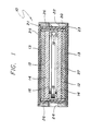
- a projector transducer according to our invention is shown generally at numeral and includes two identical disks 12 of ceramic piezoelectric material such as lead zirconate titanate, each of which includes a facing of a thin metal skin or layer 13 bonded to its exterior face, which layer 13 is described in detail in the above patent No. 3,631,383.
- Each of disks 12 is backed by means of a metal backing plate 14, such backing plates being arranged back-to-back.
- Each such backing plate 14 is cemented to a center support ring 16 which is of generally rectangular "C" shaped configuration in which the open side is positioned toward the center, the overall diameter is slightly greater than that of the disks 12 and backing plates 14, and the thickness of the axial web 18 of support ring 16 is chosen such that it will be substantially compliant when the disks 12 are energized.
- the inwardly directed flanges 19 of center support ring 16 are only of sufficient length as to provide a secure cement bond with the backing plates 14 so that the backing plates will not separate from the support ring 16 under high power output at limited depths.
- an outer handling ring 20 having openings 22 and 24 spaced 180 degrees apart for mounting of electrical connectors, not shown. Carried within ring 20 such that it surrounds and retains the electrical connecting wires from the disks 12 and fills the space between ring 20 and disks 12 and backing plates 14 is a layer of polyurethane potting compound 26. Handling ring 20 is notched at its top and bottom edges as shown at numerals 21 and 23 to receive thin neoprene disks 25 and 27 which are bonded over the entire flat surfaces of the transducer including the thin layer 13, potting compound 26 and notches 21 and 23 to provide waterproofing.
- Each of the ceramic disks 12 is plated with a thin layer of silver or copper to provide maximum conductivity across its surfaces and each side of each ceramic disk has fastened thereto a series of electrical connector tabs.
- these tabs are in the form of radially oriented metal strips 28 which are soldered to the plated surfaces of the disks 12 such that they extend beyond the surfaces of the disks and are usable as connectors.
- the tabs 28 are radially displaced 120 degrees from each other on each face of the disk and those on one side of the disks 12 are displaced sixty degrees from the tabs on the opposite side to minimize the danger of short circuits between tabs from opposite sides of the disk.
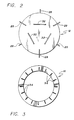
- each disk 12 between itself and the backing plates 14, a second set of tabs 32 are arranged in a pattern on the surface as shown in Figure 2.
- These metal strips may be approximately 0.003 in. thick, 0.25 in. wide and 3 to 4 inches long, more or less, depending upon the diameters of disks 12.
- Other suitable connector arrangements may be used depending upon requirements.
- Figure 3 is a plan view of the center support ring 16 showing a plurality of slots 34 which are, or may be, cut in the inwardly directed flanges of the center support ring to add to the compliance of the ring.
- the number of slots 34 shown are 16, spaced 22 1/2 degrees apart. The slots are cut the entire depth of the flanges to the axial web.
- the spacing and number of such slots may differ but they are preferably provided in fairly large numbers to enhance the compliance of the center support ring 16.
- Other modifications may occur to those skilled in the art and within the scope of the appended claims.
Landscapes
- Engineering & Computer Science (AREA)
- Mechanical Engineering (AREA)
- Transducers For Ultrasonic Waves (AREA)
Applications Claiming Priority (2)
| Application Number | Priority Date | Filing Date | Title |
|---|---|---|---|
| US06/924,958 US4709361A (en) | 1986-10-30 | 1986-10-30 | Flexural disk transducer |
| US924958 | 1986-10-30 |
Publications (3)
| Publication Number | Publication Date |
|---|---|
| EP0265679A2 true EP0265679A2 (fr) | 1988-05-04 |
| EP0265679A3 EP0265679A3 (en) | 1988-12-21 |
| EP0265679B1 EP0265679B1 (fr) | 1992-07-22 |
Family
ID=25450980
Family Applications (1)
| Application Number | Title | Priority Date | Filing Date |
|---|---|---|---|
| EP87114129A Expired EP0265679B1 (fr) | 1986-10-30 | 1987-09-28 | Transducteur à disque de flexion |
Country Status (4)
| Country | Link |
|---|---|
| US (1) | US4709361A (fr) |
| EP (1) | EP0265679B1 (fr) |
| JP (1) | JP2579173B2 (fr) |
| DE (1) | DE3780559T2 (fr) |
Cited By (2)
| Publication number | Priority date | Publication date | Assignee | Title |
|---|---|---|---|---|
| EP0586828A3 (fr) * | 1992-08-11 | 1995-01-18 | Prakla Seismos Gmbh | Hydrophone. |
| GB2306075A (en) * | 1995-08-11 | 1997-04-23 | Ind Tech Res Inst | Piezoelectric full-range loudspeaker |
Families Citing this family (22)
| Publication number | Priority date | Publication date | Assignee | Title |
|---|---|---|---|---|
| US5210720A (en) * | 1987-05-20 | 1993-05-11 | The B. F. Goodrich Company | Compliant tube baffle |
| US5001680A (en) * | 1988-02-18 | 1991-03-19 | The B. F. Goodrich Company | Compliant tube baffle |
| US4887247A (en) * | 1988-02-18 | 1989-12-12 | The B. F. Goodrich Company | Compliant tube baffle |
| US4972390A (en) * | 1989-04-03 | 1990-11-20 | General Instrument Corp. | Stack driven flexural disc transducer |
| US5852589A (en) * | 1990-07-19 | 1998-12-22 | Raytheon Company | Low cost composite transducer |
| US5218576A (en) * | 1992-05-22 | 1993-06-08 | The United States Of America As Represented By The Secretary Of The Navy | Underwater transducer |
| DE19538678C2 (de) * | 1995-10-17 | 1998-12-10 | Endress Hauser Gmbh Co | Anordnung zur Überwachung eines vorbestimmten Füllstands einer Flüssigkeit in einem Behälter |
| DE19538696C2 (de) * | 1995-10-17 | 1997-09-25 | Endress Hauser Gmbh Co | Anordnung zur Überwachung eines vorbestimmten Füllstands einer Flüssigkeit in einem Behälter |
| US5677894A (en) * | 1995-12-27 | 1997-10-14 | Syntron Inc. | Hydrophone structure with center pin |
| US5815466A (en) * | 1995-12-27 | 1998-09-29 | Syntron, Inc. | Hydrophone structure with reverse bend of piezoelectric element |
| US7179551B2 (en) | 1999-02-12 | 2007-02-20 | General Electric Company | Poly(arylene ether) data storage media |
| WO2000048172A2 (fr) | 1999-02-12 | 2000-08-17 | General Electric Company | Support de stockage de donnees |
| US6341661B1 (en) | 2000-04-19 | 2002-01-29 | L3 Communications Corporation | Bow dome sonar |
| RU2194372C2 (ru) * | 2001-02-16 | 2002-12-10 | Баев Михаил Юрьевич | Гидроакустический изгибный приемник |
| US6784600B2 (en) * | 2002-05-01 | 2004-08-31 | Koninklijke Philips Electronics N.V. | Ultrasonic membrane transducer for an ultrasonic diagnostic probe |
| US8427901B2 (en) * | 2009-12-21 | 2013-04-23 | Pgs Geophysical As | Combined impulsive and non-impulsive seismic sources |
| CN102136268B (zh) * | 2011-01-27 | 2012-09-05 | 西北工业大学 | 一种折回式压电陶瓷低频水声换能器 |
| US9111520B2 (en) | 2013-03-12 | 2015-08-18 | Curtis E. Graber | Flexural disk transducer shell |
| US9508915B2 (en) | 2013-09-03 | 2016-11-29 | Pgs Geophysical As | Piezoelectric bender with additional constructive resonance |
| US10101480B2 (en) | 2014-10-20 | 2018-10-16 | Pgs Geophysical As | Methods and systems to separate seismic data associated with impulsive and non-impulsive sources |
| RU183658U1 (ru) * | 2018-03-29 | 2018-09-28 | Акционерное Общество "Концерн "Океанприбор" | Гидроакустический изгибный преобразователь |
| CN114189787A (zh) * | 2021-11-23 | 2022-03-15 | 中国船舶重工集团公司第七一五研究所 | 一种压力补偿极低频弯曲圆盘换能器 |
Family Cites Families (6)
| Publication number | Priority date | Publication date | Assignee | Title |
|---|---|---|---|---|
| US3255431A (en) * | 1960-10-06 | 1966-06-07 | Gulton Ind Inc | Hydrophone |
| US3249912A (en) * | 1962-08-08 | 1966-05-03 | Gen Dynamics Corp | Electromechanical transducer |
| US3465178A (en) * | 1966-09-13 | 1969-09-02 | Us Army | Driven-boundary piezoelectric crystals |
| US3631383A (en) * | 1969-07-25 | 1971-12-28 | Bendix Corp | Piezoelectric transducer configuration |
| US3663933A (en) * | 1970-07-02 | 1972-05-16 | Us Navy | Protective band for bilaminar transducer with slotted spacer ring |
| GB2050671B (en) * | 1979-06-09 | 1983-08-17 | Sony Corp | Rotary transducer head assemblies |
-
1986
- 1986-10-30 US US06/924,958 patent/US4709361A/en not_active Expired - Lifetime
-
1987
- 1987-09-28 DE DE8787114129T patent/DE3780559T2/de not_active Expired - Lifetime
- 1987-09-28 EP EP87114129A patent/EP0265679B1/fr not_active Expired
- 1987-10-28 JP JP62270478A patent/JP2579173B2/ja not_active Expired - Lifetime
Cited By (2)
| Publication number | Priority date | Publication date | Assignee | Title |
|---|---|---|---|---|
| EP0586828A3 (fr) * | 1992-08-11 | 1995-01-18 | Prakla Seismos Gmbh | Hydrophone. |
| GB2306075A (en) * | 1995-08-11 | 1997-04-23 | Ind Tech Res Inst | Piezoelectric full-range loudspeaker |
Also Published As
| Publication number | Publication date |
|---|---|
| JP2579173B2 (ja) | 1997-02-05 |
| EP0265679A3 (en) | 1988-12-21 |
| US4709361A (en) | 1987-11-24 |
| DE3780559D1 (de) | 1992-08-27 |
| JPS63122400A (ja) | 1988-05-26 |
| DE3780559T2 (de) | 1993-02-18 |
| EP0265679B1 (fr) | 1992-07-22 |
Similar Documents
| Publication | Publication Date | Title |
|---|---|---|
| US4709361A (en) | Flexural disk transducer | |
| US3142035A (en) | Ring-shaped transducer | |
| EP0210723B1 (fr) | Transducteur ultrason | |
| US5711058A (en) | Method for manufacturing transducer assembly with curved transducer array | |
| EP0872285B1 (fr) | Elément arrière conductif pour und transducteur composite | |
| US6971148B2 (en) | Method of manufacturing a multi-dimensional transducer array | |
| EP0167740B1 (fr) | Transducteur ultrasonore avec un film polymère piézoélectrique multiplié | |
| JP3210671B2 (ja) | 超音波変換器アレーとその製造方法 | |
| US4992692A (en) | Annular array sensors | |
| US3510698A (en) | Electroacoustical transducer | |
| EP0142318A2 (fr) | Transducteur à ultrasons | |
| CN101499271B (zh) | 用于邻近传感器的超声波换能器 | |
| KR20010039800A (ko) | 압전 전기 음향 변환기 | |
| EP0181506A2 (fr) | Assemblage transducteur piézo-électrique flexible | |
| GB2052918A (en) | Piezoelectric transducers | |
| JPH07507721A (ja) | 2次元超音波変換器配列 | |
| CN1860823B (zh) | 麦克风部件及其制造方法 | |
| US4972390A (en) | Stack driven flexural disc transducer | |
| US6671230B1 (en) | Piezoelectric volumetric array | |
| US3546497A (en) | Piezoelectric transducer element | |
| GB2164820A (en) | Hydrophone | |
| CN115005876B (zh) | 一种阵列超声换能器及其制备方法 | |
| US4075600A (en) | Dual resonance bender transducer | |
| US3363228A (en) | Pressure gradient hydrophone | |
| US5099461A (en) | Underwater electroacoustic transducers |
Legal Events
| Date | Code | Title | Description |
|---|---|---|---|
| PUAI | Public reference made under article 153(3) epc to a published international application that has entered the european phase |
Free format text: ORIGINAL CODE: 0009012 |
|
| AK | Designated contracting states |
Kind code of ref document: A2 Designated state(s): DE FR GB IT |
|
| PUAL | Search report despatched |
Free format text: ORIGINAL CODE: 0009013 |
|
| AK | Designated contracting states |
Kind code of ref document: A3 Designated state(s): DE FR GB IT |
|
| 17P | Request for examination filed |
Effective date: 19890613 |
|
| 17Q | First examination report despatched |
Effective date: 19910605 |
|
| RAP1 | Party data changed (applicant data changed or rights of an application transferred) |
Owner name: ALLIED-SIGNAL INC. (A DELAWARE CORPORATION) |
|
| GRAA | (expected) grant |
Free format text: ORIGINAL CODE: 0009210 |
|
| AK | Designated contracting states |
Kind code of ref document: B1 Designated state(s): DE FR GB IT |
|
| ITF | It: translation for a ep patent filed | ||
| REF | Corresponds to: |
Ref document number: 3780559 Country of ref document: DE Date of ref document: 19920827 |
|
| ET | Fr: translation filed | ||
| PLBE | No opposition filed within time limit |
Free format text: ORIGINAL CODE: 0009261 |
|
| STAA | Information on the status of an ep patent application or granted ep patent |
Free format text: STATUS: NO OPPOSITION FILED WITHIN TIME LIMIT |
|
| 26N | No opposition filed | ||
| REG | Reference to a national code |
Ref country code: GB Ref legal event code: IF02 |
|
| PGFP | Annual fee paid to national office [announced via postgrant information from national office to epo] |
Ref country code: GB Payment date: 20060804 Year of fee payment: 20 |
|
| PGFP | Annual fee paid to national office [announced via postgrant information from national office to epo] |
Ref country code: FR Payment date: 20060906 Year of fee payment: 20 |
|
| PGFP | Annual fee paid to national office [announced via postgrant information from national office to epo] |
Ref country code: DE Payment date: 20060929 Year of fee payment: 20 |
|
| PGFP | Annual fee paid to national office [announced via postgrant information from national office to epo] |
Ref country code: IT Payment date: 20060930 Year of fee payment: 20 |
|
| REG | Reference to a national code |
Ref country code: GB Ref legal event code: PE20 |
|
| PG25 | Lapsed in a contracting state [announced via postgrant information from national office to epo] |
Ref country code: GB Free format text: LAPSE BECAUSE OF EXPIRATION OF PROTECTION Effective date: 20070927 |