EP0265688A2 - Einrichtung (Kühleinrichtung) zur Konstanthaltung der Temperatur in den funktionell kritischen Temperaturzonen einer Kunststoff-Spritzgiessmaschine - Google Patents
Einrichtung (Kühleinrichtung) zur Konstanthaltung der Temperatur in den funktionell kritischen Temperaturzonen einer Kunststoff-Spritzgiessmaschine Download PDFInfo
- Publication number
- EP0265688A2 EP0265688A2 EP87114192A EP87114192A EP0265688A2 EP 0265688 A2 EP0265688 A2 EP 0265688A2 EP 87114192 A EP87114192 A EP 87114192A EP 87114192 A EP87114192 A EP 87114192A EP 0265688 A2 EP0265688 A2 EP 0265688A2
- Authority
- EP
- European Patent Office
- Prior art keywords
- valve
- channel
- cooling
- cooling device
- inlet channel
- Prior art date
- Legal status (The legal status is an assumption and is not a legal conclusion. Google has not performed a legal analysis and makes no representation as to the accuracy of the status listed.)
- Granted
Links
Images


Classifications
-
- G—PHYSICS
- G05—CONTROLLING; REGULATING
- G05D—SYSTEMS FOR CONTROLLING OR REGULATING NON-ELECTRIC VARIABLES
- G05D23/00—Control of temperature
- G05D23/19—Control of temperature characterised by the use of electric means
- G05D23/1919—Control of temperature characterised by the use of electric means characterised by the type of controller
-
- B—PERFORMING OPERATIONS; TRANSPORTING
- B29—WORKING OF PLASTICS; WORKING OF SUBSTANCES IN A PLASTIC STATE IN GENERAL
- B29C—SHAPING OR JOINING OF PLASTICS; SHAPING OF MATERIAL IN A PLASTIC STATE, NOT OTHERWISE PROVIDED FOR; AFTER-TREATMENT OF THE SHAPED PRODUCTS, e.g. REPAIRING
- B29C45/00—Injection moulding, i.e. forcing the required volume of moulding material through a nozzle into a closed mould; Apparatus therefor
- B29C45/17—Component parts, details or accessories; Auxiliary operations
- B29C45/72—Heating or cooling
-
- Y—GENERAL TAGGING OF NEW TECHNOLOGICAL DEVELOPMENTS; GENERAL TAGGING OF CROSS-SECTIONAL TECHNOLOGIES SPANNING OVER SEVERAL SECTIONS OF THE IPC; TECHNICAL SUBJECTS COVERED BY FORMER USPC CROSS-REFERENCE ART COLLECTIONS [XRACs] AND DIGESTS
- Y10—TECHNICAL SUBJECTS COVERED BY FORMER USPC
- Y10T—TECHNICAL SUBJECTS COVERED BY FORMER US CLASSIFICATION
- Y10T137/00—Fluid handling
- Y10T137/8593—Systems
- Y10T137/877—With flow control means for branched passages
- Y10T137/87877—Single inlet with multiple distinctly valved outlets
-
- Y—GENERAL TAGGING OF NEW TECHNOLOGICAL DEVELOPMENTS; GENERAL TAGGING OF CROSS-SECTIONAL TECHNOLOGIES SPANNING OVER SEVERAL SECTIONS OF THE IPC; TECHNICAL SUBJECTS COVERED BY FORMER USPC CROSS-REFERENCE ART COLLECTIONS [XRACs] AND DIGESTS
- Y10—TECHNICAL SUBJECTS COVERED BY FORMER USPC
- Y10T—TECHNICAL SUBJECTS COVERED BY FORMER US CLASSIFICATION
- Y10T137/00—Fluid handling
- Y10T137/8593—Systems
- Y10T137/877—With flow control means for branched passages
- Y10T137/87909—Containing rotary valve
Definitions
- the invention relates to a cooling device according to the preamble of claim 1.
- Tests have shown that the spread of the weight and dimensions of the injection molded parts of an injection mold from the temperature constancy in the critical areas of the injection molding machine, in particular the temperature constancy of the injection mold and the feed area of the granules into the plasticizing cylinder, but also from the temperature constancy of the pressure oil in the hydraulic Circulation to a much higher degree than previously assumed, is dependent.
- the object of the invention is to further develop a cooling device of the type mentioned at the outset in such a way that the deviations from the target temperature in the temperature-critical areas can be substantially reduced with a reasonable technical outlay and the temperature constancy achieved can be maintained almost indefinitely without any significant maintenance work can be.
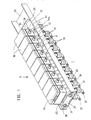
- the cooling device cools areas of the plastic injection molding machine that require temperature control or are critical to temperature by means of a liquid medium, in particular using tap water. It comprises a distributor and control unit (unit S in Fig.1), to which several cooling circuits are connected, in which the areas or functional units in need of cooling (for example the injection mold, the oil of the hydraulic circuit to be tempered in a cooler, the intake area of the plastic granules coming into the plasticizing cylinder).
- the cooling circuits branch off from a common inflow channel Z and open into a common outflow channel A.
- Inflow channel Z and outflow channel A are composed of molded pieces F made of high-polymer material and arranged in a row as channel sections 13, 13 '.
- the channel sections 13 lying on one side form the inlet channel Z and the channel sections 13 ⁇ lying at a distance from them form the parallel outlet channel A.
- Each shaped piece has a connecting piece 13 ⁇ for feeding the cooling medium into the cooling circuit and a connecting piece 13 13 for the return of the Coolant in the drain channel A.
- the connecting pieces 13 ′′′ of the distributor unit are arranged radially to the drain channel and the connecting pieces 13 ⁇ parallel to the connecting pieces 13 ′′′ for feeding the cooling medium into the cooling circuits between the inlet channel Z and the outlet channel A, as can be seen particularly from FIG. 4.
- valve channel 60 in FIG. 6 is a channel running perpendicular to the inlet channel Z and outlet channel A, which is covered by the valve seat disk 53 to form the valve chamber 59.
- the flow rates in the cooling circuits are determined by means of a computer R connected to the central computer of the plastic injection molding machine by means of ceramic rotary valves K. (Fig. 4) adjustable.
- the valve chambers 59 receiving these ceramic rotary valves K are delimited on both sides by the channel sections 13, 13 ⁇ of a shaped piece F and on the back by a motor-gear housing 15 (FIG. 4).
- each fitting F forms the housing for a ceramic rotary valve K, whose axis of rotation vv is coaxial with the adjacent connecting piece 13utzen.
- the fittings F are axially clamped to one another by tie rods 20 made of stainless steel, which are arranged coaxially in the inflow channel Z or outflow channel A and which lie in a plane ee which is perpendicular to the valve axis vv and thus also perpendicular to the axes of all connecting pieces 13 ⁇ , 13 ′′′ stands.
- the valve chambers 59 communicate with the inlet channel Z via sections of the adjacent channel sections 13, which sections are symmetrical to the plane ee, which can be seen in particular from FIG. 4.
- a cuboid motor gear housing 15, which is closed off at the rear by a cover 16, is fastened to each shaped piece F by means of elements 48.
- the side of the motor-transmission housing 15 facing the fitting F runs parallel to the plane ee (FIG. 4).
- a printed circuit board 42 with electronic components 43 which is perpendicular to the valve axis vv, is arranged in each motor-transmission housing 15 on the back of a stepper motor 44 driving the ceramic rotary valve K, the drive axis 49 of which is parallel to the valve axis vv.
- the drive shaft 49 meshes with a gear of a reduction gear 45, which is mounted between boards 45 ⁇ .
- a limit switch 46 (FIG. 4) for the valve body disk 52 can be switched by the control cam 47 ⁇ of a control axis 47.
- the drive axis 50 of the reduction gear 45 is, as can be seen from FIG.
- the ceramic rotary valve K consists of a ceramic valve seat disk 53 and a ceramic valve body disk 52 which bears against it under constant pressure and which is rotatable via the drive shaft 51 with the aid of the stepping motor 44, that is to say driven by an impulse-controlled electric motor.
- the constant contact pressure of the Ventilstiz disc 53 is generated with the aid of a prestressed coil spring 55, which surrounds the drive shaft 51 and the back of the motor gear housing 15 in the area of a cylindri Forming 15a is present.
- the pot-like shape 15a is centered in a corresponding recess in the shaped piece F and delimits the valve chamber 59 with its end face. At the same time, it forms the central bearing 15b for the drive shaft 51.
- An outer sealing ring 57 and an inner sealing ring 56 are provided for sealing.
- a driving profile 51a of the drive axle 51 dips as a driving clutch in a fitting fit into a corresponding recess in the valve body disk 52.
- the rotationally symmetrical end section 51b of the drive shaft 51 plunges into a corresponding central recess 53 ⁇ of the ceramic valve seat disk 53 and is centered there.
- the ceramic valve seat disk 53 is fixed in a rotationally fixed manner in the plastic molding F.
- valve seat disk 53 Two diametrical pegs of the shaped part F are used for fixing, which fit into corresponding recesses in the valve seat disk 53 in a snug fit (not visible in the drawing).
- a sealing ring 54 To seal the valve chamber 59 from the interior of the connecting piece 13 ⁇ is a sealing ring 54, which is arranged in an annular groove in a support shoulder for the valve seat washer 53.
- the valve seat washer 53 is pressed via the valve body washer 52 by the prestressed coil spring 55 into its rotationally fixed fit.
- Valve seat disk 53 and valve body disk 52 are designed such that diametrical, circular arc-shaped flow slots 61 of increasing or decreasing length result when the valve body disk 53 is rotated.
- sleeve-shaped connecting pieces 11, 12 for the inflow channel Z and the outflow channel A are connected via a valve-free identical branch fitting F ⁇ .
- the shaped pieces F and the branch shaped piece F ⁇ are centered on one another in that a front axial centering flange 13a ⁇ of the channel sections 13 ⁇ and a rear axial centering flange 13a of the channel sections 13 of the shaped pieces F and the branch shaped piece F ⁇ are centered, i.e. in a snug fit in one engage corresponding concentric recess of the adjacent fitting F or the branch fitting F ⁇ or the connector 11. All engagement joints are each sealed by means of a sealing ring 21 (Fig. 2.4).
- the termination of the unit S at the other end is constructed analogously using an adapter ring 22, sealing caps 23, a fastening tab 24, sealing rings 21, 25 and screws 27 and washers 26.
- Rotation-symmetrical sleeves (housing sleeves 33) are coaxially accommodated in the identical connecting pieces 13 ⁇ ; 13 ′′′ of inlet channel Z and outlet channel A.
- shut-off valves V are arranged, as shown in FIGS. 4.5 can be seen.
- These shut-off valves V are designed such that they close automatically when the connectable connecting nipple 37 is removed.
- the valve bodies 30 of the shut-off valves V are kept at a distance from their valve seats 33a (FIG. 3) by the coupled connecting nipples 37 against the action of coaxial coil springs 29, which are formed by the housing sleeves 33 and are supported on retaining disks 28.
- Valve body 30 and housing sleeves 33 are provided with sealing rings 31, 32.
- connection sockets 13 ⁇ , 13 ′′′ are each surrounded by a collet 35.
- Tongues 35 ⁇ which axially protrude from the associated housing sleeve 33, are axially displaced by means of a surrounding clamping ring 34 Clamping position can be transferred. In this grasp these tongues 35 ⁇ an annular rib 37 ⁇ of the connecting nipple 37th
- the computer R is accommodated in a computer housing 14 connected to the branch fitting F ⁇ , which is designed identically with the motor-gear housing 15 of the other fittings F.
- the computer housing 14, which is likewise closed at the rear by a cover 16, has two parallel printed circuit boards 38 with electronic components 41. These are fastened parallel and symmetrical to the valve axis v-v of the adjacent rotary valve K in the computer housing 14.
- the motor-gear housing 15 are electrically connected to one another by means of plug connections 19, 19 ⁇ (socket part 19 and pin part 19 ⁇ ). On each narrow side of the motor-gear housing 15 there is a socket 18 for the line (sensor line) leading to the sensor at the cooling zone of the cooling circuit.
- the identical computer housing 14 has a multipole connection 17 arranged in an analog manner for the supply line to the central computer of the plastic injection molding machine (FIG. 1,3).
- connection 17 With 40 (Fig. 2) connecting lines for connection 17 (Fig. 3), with 41, 43 electrical components and with 58 connecting lines to the sensor connections 18 are designated (Fig. 2, 4).
- valve-free branch molding F ⁇ cooling circuit leads to the central computer R ⁇ of the plastic injection molding machine receiving cabinet 66 (Fig. 3).
- This control cabinet can be locked airtight because it is freed from keyboards.
- a heat exchanger 62 which is located in the cooling circuit, is arranged in it.
- the cooling circuit is controlled by means of a thermal sensor 63 via the central computer R ⁇ through a shutoff valve 64, which opens when the set temperature in the control cabinet 66 is exceeded.
- An air-circulating device 65 in particular a fan, arranged in the switchgear cabinet 66 ensures increased air circulation in the switchgear cabinet.
- control unit S from identical fittings F; F ⁇ and identical associated motor gearboxes 15 and an identical computer housing 14 enables an increase or decrease in the number of cooling circuits by adding or removing fittings F without any noteworthy effort.
Landscapes
- Engineering & Computer Science (AREA)
- Manufacturing & Machinery (AREA)
- Mechanical Engineering (AREA)
- Physics & Mathematics (AREA)
- General Physics & Mathematics (AREA)
- Automation & Control Theory (AREA)
- Injection Moulding Of Plastics Or The Like (AREA)
- Moulds For Moulding Plastics Or The Like (AREA)
Abstract
Description
- Die Erfindung bezieht sich auf eine Künhleinrichtung entsprechend dem Oberbegriff des Patentanspruches 1.
- Bei den üblichen Kühleinrichtungen dieser Art (US-PS 3.974.857) werden die Kühlkreisläufe mittels manuell zu betätigender Hähne gesteuert, wobei der ungefähre Kühlbedarf an der Schwebehöhe von Schwebekörpern in vertikalen Glasrohrabschnitten der Kühlkreisläufe an Skalen ablesbar ist.
- Aus der US-PS 3 566 439 ist auch eine Einrichtung zur Temperatursteuerung von Formen bei Maschinen zur Verarbeitung von heißem oder geschmolzenem Material bekannt, mit einer von einem gemeinsamen Zuflußkanal abzweigenden Versorgung und mit Vorrichtungen zur Erfassung des jeweiligen Kühlbedarfes und der bedarfsorientierten Veränderung der Durchflußmengen in den Kühlkreisläufen, bei der die Durchflußmengen in den Kühlkreisläufen mit Hilfe eines Rechners mittels Ventilen regelbar sind, wobei die Ventile durch Elektromotoren betätigt werden.
- In Versuchen ergab sich, daß die Streuung des Gewichts und der Abmessungen der Spritzlinge einer Spritzgießform von der Temperaturkonstanz in den kritischen Bereichen der Spritzgießmaschine, insbesondere der Temperaturkonstanz der Spritzgießform und des Einzugsbereiches des Granulats in den Plastifizierzylinder, aber auch von der Temperaturkonstanz des Drucköls im hydraulischen Kreislauf in wesentlich höherem Grade als bisher angenommen, abhängig ist.
- Hiervon ausgehend liegt der Erfindung die Aufgabe zugrunde, eine Kühleinrichtung der eingangs genannten Art derart weiterzubilden, daß die Abweichungen von der Soll-Temperatur in den temperaturkritischen Bereichen bei tragbarem technischem Aufwand wesentlich reduziert werden können und die erreichte Temperaturkonstanz ohne nennenswerte Wartungsarbeiten zeitlich nahezu unbegrenzt aufrecht erhalten werden kann.
- Diese Aufgabe wird erfindungsgemäß durch die im Patentanspruch 1 genannten Merkmale gelöst.
- Es hat sich gezeigt, daß bei einer solchen Ausbildung insbesondere auch die negativen abrasiven und korrosiven Wirkungen von im Kühlmedium, insbesondere im Kühlwasser gelösten Fremdstoffen und dort aufgeschwemmten Feststoffen nahezu vollständig und zeitlich unbegrenzt unterdrückt werden können. Bei dieser Lösung liegen zudem die Voraussetzungen vor, daß durch ein kostensenkendes Zusammenwirken von spritztechnischen aund ventiltechnischen Maßnahmen der insgesamt etwas höhere ventil- und regeltechnische Aufwand in Grenzen gehalten werden kann. Dabei war nicht nur die Erkenntnis der spezifischen Eignung keramischer Dichtflächen für eine Erhöhung der Regelgenauigkeit infolge andauernder Selbstreinigung von den Schwebstoffen relativ unreiner Kühlmedien erforderlich, vielmehr mußte auch ein Weg gefunden werden, der den Einsatz solcher Dichtflächen bei rationeller Serienfertigung ermöglicht.
- Nachstehend wird die Erfindung anhand der Zeichnung an einem Ausführungsbeispiel erläutert.
- Es zeigen:
- Fig. 1 die Kühleinrichtung (ohne Fühlerleitungen)in perspektivischer Darstellung,
- Fig. 2 einen aufgeschnittenen Ausschnitt aus der Verteiler- und Regeleinheit gemäß Fig. 1 in Seitenansicht und in vergrößerter Darstellung,
- Fig. 3, 4 Schnitte nach Linien III-III und IV-IV von Fig. 2 in vergrößerter Darstellung (rechter Kanalabschnitt (13ʹ) ist nicht geschnitten), und
- Fig. 5 das endständige Formstück (Fʹ) der Kühleinrichtung gemäß Fig. 1 mit Rechnergehäuse und dem Anschluß eines Kühlkreislaufes und
- Fig. 6 das den Ventilkanal (61) afuweisende Formstück (F) vom Getriebegehäuse her gesehen.
- Die Kühleinrichtung kühlt temperierbedürftige bzw. temperaturkritische Bereiche der Kunststoff-Spritzgießmaschine mittels eines flüsisgen Mediums, insbesondere mittels Leitungswasser. Sie umfaßt eine Verteiler- und Steuereinheit (Einheit S in Fig.1), an welche mehrere Kühlkreisläufe angeschlossen sind, in welchen die kühlbedürftigen Bereiche bzw. Funktionseinheiten (z.B. die Spritzgießform, das in einem Kühler zu temperierende Öl des Hydraulikkreislaufes, der Einzugsbereich des aus einem Vorratsraum kommenden Kunststoffgranulats in den Plastifizierzylinder)liegen. Die Kühlkreisläufe zweigen von einem gemeinsamen Zuflußkanal Z ab und münden in einen gemeinsamen Abflußkanal A. Zuflußkanal Z und Abflußkanal A sind durch aneinander gereihte, als Kanalabschnitte 13,13ʹ gestaltete Formstücke F aus hochpolymerem Werkstoff zusammengesetzt. Dabei bilden die auf der einen Seite liegenden Kanalabschnitte 13 den Zulaufkanal Z und die im Abstand von diesen liegenden Kanalabschnitte 13ʹ den parallelen Abflußkanal A. Jedes Formstück weist einen Anschlußstutzen 13ʺ für die Einspeisung des Kühlmediums in den Kühlkrieslauf und ein Anschlußstutzen 13‴ für die Rückführung des Kühlmediums in den Abflußkanal A auf. Dabei sind die Anschlußstutzen 13‴ der Verteilereinheit radial zum Abflußkanal und die zu den Anschlußstutzen 13‴ parallelen Anschlußstutzen 13ʺ für die Einspeisung des Kühlmediums in die Kühlkreisläufe zwischen Zulaufkanal Z und Ablaufkanal A angeordnet, wie insbesondere aus Fig. 4 ersichtlich.
- Zwischen diesen beiden Kanalabschnitten 13; 13ʹ ist ein senkrecht zum Zulaufkanal Z und Ablaufkanal A verlaufender Kanal (Ventilkanal 60 in Fig. 6) eingeformt, der zu Bildung der Ventilkammer 59 durch die Ventilsitz-Scheibe 53 abgedeckt ist.
- Die Durchflußmengen in den Kühlkreisläufen sind mit Hilfe eines mit dem zentralen Rechner der Kunststoff-Spritzgießmaschine in Verbindung stehenden Rechners R mittels keramischer Drehventile K (Fig. 4) regelbar. Die diese keramischen Drehventile K aufnehmenden Ventilkammern 59 sind beidseits von den Kanalabschnitten 13, 13ʹ eines Formstückes F und rückseitig von einem Motor-Getriebegehäuse 15 begrenzt (Fig. 4). Insoweit bildet jedes Formstück F das Gehäuse für ein keramisches Drehventil K, dessen Drehachse v-v koaxial zum benachbarten Anschlußstutzen 13ʺ liegt. Die Formstücke F sind durch Zuganker 20 aus Edelstahl miteinander axial verspannt, welche koaxial im Zuflußkanal Z bzw. Abflußkanal A angeordnet sind und welche in einer Ebene e-e liegen, die senkrecht zur Ventilachse v-v und somit auch senkrecht zu den Achsen aller Anschlußstutzen 13ʺ, 13‴ steht. Die Ventilkammern 59 kommunizieren mit dem Zulaufkanal Z über Anschnitte der benachbarten Kanalabschnitte 13, welche Anschnitte symmetrisch zur Ebene e-e liegen, was insbesondere aus Fig. 4 erkennbar ist. An jedem Formstück F ist ein rückseitig von einem Deckel 16 abgeschlossenes, quaderförmiges Motor-Getriebegehäuse 15 mittels Elementen 48 befestigt. Dabei verläuft die dem Formstück F zugewandte Seite des Motor-Getriebegehäuses 15 parallel zur Ebene e-e (Fig.4). In jedem Motor-Getriebegehäuse 15 ist eine senkrecht zur Ventilachse v-v stehende Printplatte 42 mit elektronischen Bauteilen 43 an der Rückseite eines das keramische Drehventil K antreibenden Schrittmotors 44 angeordnet, dessen Antriebsachse 49 parallel zur Ventilachse v-v liegt. Die Antriebsachse 49 kämmt mit einem Zahnrad eines Untersetzungsgetriebes 45, das zwischen Platinen 45ʹ gelagert ist. Ein Endlagerschalter 46 (Fig. 4) für die Ventilkörperscheibe 52 ist vom Steuernocken 47ʹ einer Steuerachse 47 schaltbar. Die Antriebsachse 50 des Untersetzungsgetriebes 45 ist, wie aus Fig. 4 ersichtlich, mit der Antriebsachse 51 für das keramische Drehventeil K durch ein axiales Kupplungsprofil gekuppelt. Das keramische Drehventil K besteht aus einer keramischen Ventilsitz-Scheibe 53 und einer an dieser unter ständigem Druck anliegenden keramischen Ventilkörper-Scheibe 52, die über die Antriebsachse 51 mit Hilfe des Schrittmotors 44 drehbar, also von einem impulsgesteuerten Elektromotor angetrieben ist. Der ständige Anlagedruck der Ventilstiz-Scheibe 53 wird mit Hilfe einer vorgespannten Schraubenfeder 55 erzeugt, welcher die Antriebsachse 51 umschließt und die rückseitig am Motor-Getriebegehäuse 15 im Bereich einer zylindri schen Ausformung 15a anliegt. Die topfartige Ausformung 15a taucht zentrierend in eine entsprechende Ausnehmung des Formstückes F ein und begrenzt mit ihrer Stirnseite die Ventilkammer 59. Sie bildet gleichzeitig das zentrale Lager 15b für die Antriebsachse 51. Zur Abdichtung sind ein äußerer Dichtring 57 und ein innerer Dichtring 56 vorgesehen. Ein Mitnahmeprofil 51a der Antriebsachse 51 taucht als Mitnahmekupplung im Paßsitz in eine entsprechende Ausnehmung der Ventilkörper-Scheibe 52 ein. Der rotationssymmetrische Endabschnitt 51b der Antriebsachse 51 taucht in eine entsprechende zentrale Ausnehmung 53ʹ der keramischen Ventilsitz-Scheibe 53 ein und ist dort zentriert. Die keramische Ventilsitz-Scheibe 53 ist im Kunststoff-Formstück F drehfest festgelegt. Zur Festlegung dienen zwei diametrale Zapfen des Formstückes F, die in entsprechende Ausnehmungen der Ventilsitz-Scheibe 53 im Paßsitz eintauchen (in der Zeichnung nicht sichtbar). Zur Abdichtung der Ventilkammer 59 gegenüber dem Innenraum des Anschlußstutzens 13ʺ dient ein Dichtring 54, der in einer Ringnut in einer Auflageschulter für die Ventilsitz-Scheibe 53 angeordnet ist. Dabei ist die Ventilsitz-Scheibe 53 über die Ventilkörper-Scheibe 52 von der vorgespannten Schraubenfeder 55 in ihren drehfesten Paßsitz gedrückt. Ventilsitz-Scheibe 53 und Ventilkörper-Scheibe 52 sind derart gestaltet, daß sich bei Drehung der Ventilkörper-Scheibe 53 diametrale, kreisbogenförmige Durchflußschlitze 61 von zunehmender bzw. abnehmender Länge ergeben.
- Wie aus Fig. 3 in Verbindung mit Fig. 1 erkennbar, sind muffenförmige Anschlußstücke 11,12 für den Zuflußkanal Z und den Abflußkanal A über ein ventilfreies identisches Zweig-Formstück Fʹ angeschlossen. Die Formstücke F und das Zweig-Formstück Fʹ sind dadurch aneinander zentriert, daß jeweils ein vorderseitiger axialer Zentrierflansch 13aʹ der Kanalabschnitte 13ʹ und ein rückseitiger axialer Zentrierflansch 13a der Kanalabschnitte 13 der Formstücke F bzw. des Zweig-Formstückes Fʹ zentrierend, also im Paßsitz in eine entsprechende konzentrische Ausnehmung des benachbarten Formstückes F bzw. des Zweig-Formstückes Fʹ bzw. des Anschlußstückes 11 eingreifen. Alle Eingriffsfugen sind je mittels Dichtring 21 abgedichtet (Fig. 2,4). Demzufolge taucht ein axialer Zentrierflansch 12a des Anschlußstückes 12 für den Zuflußkanal Z über einen Dichtring 21 in eine entsprechende Zentrierausnehmung des Zweig-Formstückes Fʹ und der Zentrierflansch 13aʹ des Formstückes F über einen Dichtring 21 in eine koaxiale Zentrierausnehmung des Anschlußstückes 11 zentrierend ein. Die mit Anschlußstutzen 11b und 12b versehenen Anschlußstücke 11 und 12 sind stirnseitig mit Verschlußkappen 23 abgedeckt, wobei zwischen dem Verschlußstück 12 und der Verschlüßkappe 23 ein Adapterring 22 eingefügt ist. Dieser hat den Zweck, den beim Anschlußstück 12 stirnseitig fehlenden Zentrierflansch zu ersetzen, um gleiche Anschlußbedingungen für die Verschlußkappe 23 zu schaffen wie beim Anschlußstück 11. Die von Schrauben 27 axial gefaßten Zuganker 20 greifen über Scheiben 26 und eine Befestigungslasche 24 axial unter Zwischenschaltung von Dichtringen 25 an den Verschlußkappen an, um die Einheit S (Fig. 1) zusammenzuhalten. Der Abschluß der Einheit S am anderen Ende ist unter Verwendung eines Adapterringes 22, von Verschlußkappen 23, einer Befestigungslasche 24, Dichtringen 21,25 sowie Schrauben 27 und Scheiben 26 analog aufgebaut.
- In den identischen Anschlußstutzen 13ʺ;13‴ von Zulaufkanal Z und Ablaufkanal A sind rotationssymmetrische Muffen (Gehäusemuffen 33) koaxial aufgenommen. In diesen sind Verschlußventile V angeordnet, wie aus den Fign. 4,5 ersichtlich. Diese Verschlußventile V sind derart ausgebildet, daß sie bei Abnahme der ankuppelbaren Anschlußnippel 37 automatisch schließen. Zu diesem Zweck sind die Ventilkörper 30 der Verschlußventile V durch die angekuppelten Anschlußnippel 37 entgegen der Wirkung von koaxialen Schraubenfedern 29 Abstand von ihren Ventilsitzen 33a (Fig.3)gehalten, die durch die Gehäusemuffen 33 gebildet und an Haltescheiben 28 widergelagert sind. Ventilkörper 30 und Gehäusemuffen 33 sind mit Dichtringen 31,32 versehen. Die aus den Anschlußstutzen 13ʺ,13‴ axial hervorragenden Endabschnitte der in diesen Anschlußstutzen zentrierten Gehäusemuffen 33 sind je von einer Spannzange 35 umschlossen. Spannzungen 35ʹ, welche die zugehörige Gehäusemuffe 33 axial überragen, sind mittels eines umschließenden Spannringes 34 durch axiales Verschieben in Spannposition überführbar. In dieser umgreifen diese Spannzungen 35ʹ eine Ringrippe 37ʹ des Anschlußnippels 37.
- Der Rechner R ist in einem an das Zweig-Formstück Fʹ angeschlossenen Rechnergehäuse 14 aufgenomen, das mit den Motor-Getriebegehäusen 15 der übrigen Formstücke F identisch gestaltet ist. Das rückseitig ebenfalls von einem Deckel 16 abgeschlossene Rechnergehäuse 14 weist zwei parallele Printplatten 38 mit elektronischen Bauteilen 41 auf. Diese sind parallel und symmetrisch zur Ventilachse v-v des benachbarten Drehventils K im Rechnergehäuse 14 befestigt. Die Motor-Getriebegehäuse 15 sind mittels Steckverbindungen 19, 19ʹ (Buchsenteil 19 und Stiftteil 19ʹ) miteinander elektrisch verbunden. Auf je einer Schmalseite der Motor-Getriebegehäuse 15 ist eine Steckbuchse 18 für die zum Fühler an der Kühlzone des Kühlkreislaufes führende Leitung (Fühlerleitung) angeordnet. Das identische Rechnergehäuse 14 weist einen analog angeordneten vielpoligen Anschluß 17 für die Versorgungsleitung zum zentralen Rechner der Kunststoff-Spritzgießmaschine auf (Fig. 1,3). Mit 40 (Fig. 2) sind Anschlußleitungen zum Anschluß 17 (Fig. 3), mit 41, 43elektrische Bauteile und mit 58 Anschlußleitungen zu den Fühleranschlüssen 18 bezeichnet (Fig. 2, 4).
- Der vom ventilfreien Zweig-Formstück Fʹ abgehende Kühlkreislauf führt zu dem den zentralen Rechner Rʹ der Kunststoff-Spritzgießmaschine aufnehmenden Schaltschrank 66 (Fig. 3). Dieser Schaltschrank ist luftdicht abschließbar, da er von Tastaturen befreit ist. In ihm ist ein Wärmetauscher 62 angeordnet, der sich im Kühlkreislauf befindet. Der Kühlkreislauf ist mit Hilfe eines Thermofühlers 63 über den zentralen REchner Rʹ durch ein Verschlußventil 64 gesteuert, das bei Überschreiten der Soll-Temperatur im Schaltschrank 66 öffnet. Ein im Schaltschrank 66 angeordnetes luftumwälzendes Gerät 65, insbesondere ein Ventilator, sorgt für eine erhöhte Luftumwälzung im Schaltschrank.
- Der Aufbau der Steuereinheit S aus identischen Formstücke F; Fʹ und identischen zugehörigen Motorgetriebegehäusen 15 sowie einem identischen Rechnergehäuse 14 ermöglicht eine Erhöhung bzw. Verminderung der Anzahl der Kühlkreisläufe durch Anreihung bzw. einer Wegnahme von Formstücken F ohne nennenswerten Aufwand.
Claims (10)
dadurch gekennzeichnet, daß die Durchflußmengen in den Kühlkreisläufen mit Hilfe eines Rechners (R) mittels keramischer Drehventile (K in Fig. 4) regelbar sind, deren unter ständigem Druck mit Keramikdichtflächen an Ventilsitz-Scheiben (53) anliegende Ventilkörper-Scheiben (52) mittels impulsgesteuerter Elektromotoren (Schrittmotore 44) drehbar sind,
und daß in jedes der einen Kanalabschnitt (13) für den Zulaufkanal (Z) und einen Kanalabschnitt (13ʹ) für den Ablaufkanal (A) aufweisenden Formstücke (F) zwischen diesen beiden Kanalabschnitten (13; 13ʹ) ein senkrecht zum Zulaufkanal (Z) und Ablaufkanal (A) verlaufender Kanal (Ventilkanal 60 in Fig.6)eingeformt ist,der zur Bildung der Ventilkammer (59) durch die Ventilsitz-Scheibe (53) abgedeckt ist.
Priority Applications (1)
| Application Number | Priority Date | Filing Date | Title |
|---|---|---|---|
| AT87114192T ATE82410T1 (de) | 1986-10-28 | 1987-09-29 | Einrichtung (kuehleinrichtung) zur konstanthaltung der temperatur in den funktionell kritischen temperaturzonen einer kunststoff- spritzgiessmaschine. |
Applications Claiming Priority (2)
| Application Number | Priority Date | Filing Date | Title |
|---|---|---|---|
| DE3636635 | 1986-10-28 | ||
| DE19863636635 DE3636635A1 (de) | 1986-10-28 | 1986-10-28 | Kuehleinrichtung an einer kunststoff-spritzgiessmaschine |
Publications (3)
| Publication Number | Publication Date |
|---|---|
| EP0265688A2 true EP0265688A2 (de) | 1988-05-04 |
| EP0265688A3 EP0265688A3 (en) | 1989-10-11 |
| EP0265688B1 EP0265688B1 (de) | 1992-11-11 |
Family
ID=6312635
Family Applications (1)
| Application Number | Title | Priority Date | Filing Date |
|---|---|---|---|
| EP87114192A Expired - Lifetime EP0265688B1 (de) | 1986-10-28 | 1987-09-29 | Einrichtung (Kühleinrichtung) zur Konstanthaltung der Temperatur in den funktionell kritischen Temperaturzonen einer Kunststoff-Spritzgiessmaschine |
Country Status (6)
| Country | Link |
|---|---|
| US (1) | US4768559A (de) |
| EP (1) | EP0265688B1 (de) |
| JP (1) | JPS63115714A (de) |
| AT (1) | ATE82410T1 (de) |
| CA (1) | CA1270615A (de) |
| DE (2) | DE3636635A1 (de) |
Cited By (3)
| Publication number | Priority date | Publication date | Assignee | Title |
|---|---|---|---|---|
| EP0473891A3 (en) * | 1990-09-01 | 1992-06-03 | Karl Hehl | Apparatus to maintain temperature in an injection molding machine |
| EP0849063A1 (de) * | 1995-11-17 | 1998-06-24 | Husky Injection Molding Systems Ltd. | Modulares Kühlsystem für Spritzgiesswerkzeuge |
| US7189004B2 (en) | 1999-10-09 | 2007-03-13 | Johnson Electric S.A. | Thrust cap |
Families Citing this family (17)
| Publication number | Priority date | Publication date | Assignee | Title |
|---|---|---|---|---|
| SE463633B (sv) * | 1989-12-22 | 1990-12-17 | Mecman Ab | Ventilanslutningsramp foer montering i apparatskaap och saett att montera en dylik ramp |
| DE4032562C2 (de) * | 1990-10-13 | 1999-03-11 | Werner Kotzab | Verteileranordnung |
| DE4132541A1 (de) * | 1991-09-30 | 1993-04-01 | Herion Werke Kg | Ventilblock |
| JP3486238B2 (ja) * | 1994-09-21 | 2004-01-13 | Smc株式会社 | 切換弁 |
| US6419476B1 (en) | 1998-08-25 | 2002-07-16 | Joseph P. Ouellette | Thermally insulated runner manifold and injection nozzle construction for plastic molding apparatus |
| DE20109053U1 (de) * | 2001-05-30 | 2002-10-10 | Reich KG Regel- und Sicherheitstechnik, 35713 Eschenburg | Ventilvorrichtung und Verteilervorrichtung |
| US6666458B2 (en) * | 2002-02-12 | 2003-12-23 | George J. Coates | Valve seal for rotary valve engine |
| US7455280B2 (en) * | 2003-12-16 | 2008-11-25 | Parker-Hannifin Corporation | Tube activated cartridge/fitting valve |
| US7222642B2 (en) * | 2005-10-27 | 2007-05-29 | Emerson Electric Co. | Enhanced water valve tube stop |
| US20110265898A1 (en) * | 2007-01-26 | 2011-11-03 | Rapid Air Llc (A Wisconsin Limited Liability Company) | Sealed Manifold For Air Pump System |
| US7886387B2 (en) * | 2007-01-26 | 2011-02-15 | Rapid Air Llc | Multiple configuration air mattress pump system |
| JP2010012683A (ja) * | 2008-07-03 | 2010-01-21 | Shisuko:Kk | マニホールド |
| CN102336010A (zh) * | 2011-11-01 | 2012-02-01 | 太仓市民星塑料厂 | 一种模具水冷却装置 |
| DE102016107161A1 (de) * | 2016-04-18 | 2017-10-19 | Eto Magnetic Gmbh | Pneumatische Mehrventilvorrichtung sowie Herstellverfahren |
| DE102016107160A1 (de) * | 2016-04-18 | 2017-10-19 | Eto Magnetic Gmbh | Pneumatische Mehrventilvorrichtung sowie Herstellungsverfahren |
| CN108327205B (zh) * | 2018-04-13 | 2024-03-22 | 惠州市鸿利达实业有限公司 | 一种内水切全自动生产注塑系统 |
| US10987844B1 (en) * | 2019-10-09 | 2021-04-27 | Coretech System Co., Ltd. | Clamping mechanism assembly |
Family Cites Families (11)
| Publication number | Priority date | Publication date | Assignee | Title |
|---|---|---|---|---|
| US1549758A (en) * | 1923-11-01 | 1925-08-18 | Westinghouse Air Brake Co | Locomotive air turret |
| US3025878A (en) * | 1959-06-02 | 1962-03-20 | Robert C Hupp | Mounting panel for fluid control components |
| GB1216890A (en) * | 1968-04-18 | 1970-12-23 | Telehoist Ltd | Improvements in or relating to flow controllers |
| US3566439A (en) * | 1968-11-22 | 1971-03-02 | Corning Glass Works | Temperature control system for molds |
| DE1956603B2 (de) * | 1968-11-22 | 1974-01-31 | Corning Glass Works, Corning, N.Y. (V.St.A.) | Anordnung zur Temperaturregelung von Formen |
| DE2337410A1 (de) * | 1973-07-23 | 1975-02-06 | Karl Hehl | Vorrichtung zur konstanthaltung der temperatur in den funktionell kritischen temperaturzonen einer spritzgiessmaschine |
| IT1012400B (it) * | 1973-07-23 | 1977-03-10 | Hehl Karl | Dispositivo per mantenere costante la temperatura nelle zone di tempe ratura critica per il funzionamen to in una pressa per lo stampaggio ad iniezione |
| US4399836A (en) * | 1981-04-14 | 1983-08-23 | Marotta Scientific Controls, Inc. | Self-contained closed-loop electrically operated valve |
| DE3308138A1 (de) * | 1983-03-08 | 1984-09-13 | Riedel Kälte- und Klimatechnik GmbH & Co KG, 8500 Nürnberg | Anordnung zum temperieren von einrichtungen fuer die kunststoffherstellung oder kunststoffverarbeitung |
| US4690789A (en) * | 1985-03-13 | 1987-09-01 | Dart Industries Inc. | Refrigerant cooled plastic molding, method and apparatus |
| DE3531194C1 (de) * | 1985-08-31 | 1986-12-18 | Knebel & Röttger GmbH & Co, 5860 Iserlohn | Sanitaeres Mischventil |
-
1986
- 1986-10-28 DE DE19863636635 patent/DE3636635A1/de active Granted
-
1987
- 1987-09-29 DE DE8787114192T patent/DE3782611D1/de not_active Expired - Lifetime
- 1987-09-29 AT AT87114192T patent/ATE82410T1/de not_active IP Right Cessation
- 1987-09-29 EP EP87114192A patent/EP0265688B1/de not_active Expired - Lifetime
- 1987-10-26 CA CA000550228A patent/CA1270615A/en not_active Expired - Lifetime
- 1987-10-26 JP JP62268377A patent/JPS63115714A/ja active Granted
- 1987-10-27 US US07/113,207 patent/US4768559A/en not_active Expired - Lifetime
Cited By (3)
| Publication number | Priority date | Publication date | Assignee | Title |
|---|---|---|---|---|
| EP0473891A3 (en) * | 1990-09-01 | 1992-06-03 | Karl Hehl | Apparatus to maintain temperature in an injection molding machine |
| EP0849063A1 (de) * | 1995-11-17 | 1998-06-24 | Husky Injection Molding Systems Ltd. | Modulares Kühlsystem für Spritzgiesswerkzeuge |
| US7189004B2 (en) | 1999-10-09 | 2007-03-13 | Johnson Electric S.A. | Thrust cap |
Also Published As
| Publication number | Publication date |
|---|---|
| EP0265688B1 (de) | 1992-11-11 |
| DE3636635A1 (de) | 1988-05-11 |
| DE3636635C2 (de) | 1989-01-19 |
| DE3782611D1 (de) | 1992-12-17 |
| JPH0523576B2 (de) | 1993-04-05 |
| US4768559A (en) | 1988-09-06 |
| EP0265688A3 (en) | 1989-10-11 |
| ATE82410T1 (de) | 1992-11-15 |
| CA1270615A (en) | 1990-06-26 |
| JPS63115714A (ja) | 1988-05-20 |
Similar Documents
| Publication | Publication Date | Title |
|---|---|---|
| EP0265688B1 (de) | Einrichtung (Kühleinrichtung) zur Konstanthaltung der Temperatur in den funktionell kritischen Temperaturzonen einer Kunststoff-Spritzgiessmaschine | |
| EP4077894B1 (de) | Vorrichtung zur handhabung von fluid innerhalb eines zumindest teilweise elektrisch angetriebenen fahrzeugs | |
| DE60315111T2 (de) | Sequenzdrehventil mit einer biegsamen Öffnungsplatte | |
| DE69621192T2 (de) | Durchflussregler | |
| EP1223017B1 (de) | Heisskanaldüse | |
| WO1999028108A1 (de) | Spritzgiessmaschine mit verschiebbaren formen, haltevorrichtung sowie formträger für eine solche spritzgiessmaschine | |
| DE4027791C1 (de) | ||
| EP4165333A1 (de) | Wegeventil und ventilkäfig für ein wegeventil | |
| DD244945A5 (de) | Schneckenstrangpresse mit einer zylindertemperiereinrichtung | |
| EP3488130A1 (de) | Massenstromregel- oder ventileinheit | |
| EP4045267B1 (de) | Spritzgusswerkzeug | |
| EP1053426B1 (de) | Schaltelement, insbesondere pneumatikventil | |
| EP2539061A1 (de) | Rührwerk | |
| EP0630430A1 (de) | Antrieb und lager für einen schaftlosen oe-spinnrotor | |
| EP0678675B1 (de) | Modular aufgebauter Trägerblock für elektromagnetische Wegeventile | |
| DE19934574A1 (de) | Fluidsystem | |
| EP0236317B1 (de) | Getriebeanlage für vollkettenfahrzeug | |
| DE2513094C3 (de) | Elektrische Isolierstoffgehäuse-Heizpatrone | |
| DE4242024C2 (de) | Vorrichtung zum wahlweisen Beaufschlagen von Formen für die Kunststoffverarbeitung mit einer Flüssigkeit oder einem unter Druck stehenden Gas | |
| EP2209601A2 (de) | Spritzgiessdüse | |
| DD229072A1 (de) | Temperierbarer extruderzylinder, insbesondere fuer doppelschneckenextruder | |
| DE4002173C2 (de) | Polymerformeinrichtung | |
| DE3537779C1 (en) | Valve | |
| EP1729052A1 (de) | Vorrichtung zur Verteilung von Flüssigkeiten | |
| DE69113549T2 (de) | Vulkanisiervorrichtung für Reifen. |
Legal Events
| Date | Code | Title | Description |
|---|---|---|---|
| PUAI | Public reference made under article 153(3) epc to a published international application that has entered the european phase |
Free format text: ORIGINAL CODE: 0009012 |
|
| AK | Designated contracting states |
Kind code of ref document: A2 Designated state(s): AT CH DE FR GB IT LI NL |
|
| PUAL | Search report despatched |
Free format text: ORIGINAL CODE: 0009013 |
|
| AK | Designated contracting states |
Kind code of ref document: A3 Designated state(s): AT CH DE FR GB IT LI NL |
|
| 17P | Request for examination filed |
Effective date: 19891026 |
|
| 17Q | First examination report despatched |
Effective date: 19920326 |
|
| GRAA | (expected) grant |
Free format text: ORIGINAL CODE: 0009210 |
|
| AK | Designated contracting states |
Kind code of ref document: B1 Designated state(s): AT CH DE FR GB IT LI NL |
|
| REF | Corresponds to: |
Ref document number: 82410 Country of ref document: AT Date of ref document: 19921115 Kind code of ref document: T |
|
| REF | Corresponds to: |
Ref document number: 3782611 Country of ref document: DE Date of ref document: 19921217 |
|
| ET | Fr: translation filed | ||
| ITF | It: translation for a ep patent filed | ||
| GBT | Gb: translation of ep patent filed (gb section 77(6)(a)/1977) |
Effective date: 19930215 |
|
| PLBE | No opposition filed within time limit |
Free format text: ORIGINAL CODE: 0009261 |
|
| STAA | Information on the status of an ep patent application or granted ep patent |
Free format text: STATUS: NO OPPOSITION FILED WITHIN TIME LIMIT |
|
| 26N | No opposition filed | ||
| PGFP | Annual fee paid to national office [announced via postgrant information from national office to epo] |
Ref country code: NL Payment date: 19970923 Year of fee payment: 11 |
|
| PG25 | Lapsed in a contracting state [announced via postgrant information from national office to epo] |
Ref country code: NL Free format text: LAPSE BECAUSE OF NON-PAYMENT OF DUE FEES Effective date: 19990401 |
|
| NLV4 | Nl: lapsed or anulled due to non-payment of the annual fee |
Effective date: 19990401 |
|
| PGFP | Annual fee paid to national office [announced via postgrant information from national office to epo] |
Ref country code: GB Payment date: 20010906 Year of fee payment: 15 |
|
| PGFP | Annual fee paid to national office [announced via postgrant information from national office to epo] |
Ref country code: FR Payment date: 20010917 Year of fee payment: 15 |
|
| PGFP | Annual fee paid to national office [announced via postgrant information from national office to epo] |
Ref country code: CH Payment date: 20010921 Year of fee payment: 15 |
|
| REG | Reference to a national code |
Ref country code: GB Ref legal event code: IF02 |
|
| PGFP | Annual fee paid to national office [announced via postgrant information from national office to epo] |
Ref country code: DE Payment date: 20020820 Year of fee payment: 16 |
|
| PGFP | Annual fee paid to national office [announced via postgrant information from national office to epo] |
Ref country code: AT Payment date: 20020919 Year of fee payment: 16 |
|
| PG25 | Lapsed in a contracting state [announced via postgrant information from national office to epo] |
Ref country code: GB Free format text: LAPSE BECAUSE OF NON-PAYMENT OF DUE FEES Effective date: 20020929 |
|
| PG25 | Lapsed in a contracting state [announced via postgrant information from national office to epo] |
Ref country code: LI Free format text: LAPSE BECAUSE OF NON-PAYMENT OF DUE FEES Effective date: 20020930 Ref country code: CH Free format text: LAPSE BECAUSE OF NON-PAYMENT OF DUE FEES Effective date: 20020930 |
|
| REG | Reference to a national code |
Ref country code: CH Ref legal event code: PL |
|
| GBPC | Gb: european patent ceased through non-payment of renewal fee |
Effective date: 20020929 |
|
| PG25 | Lapsed in a contracting state [announced via postgrant information from national office to epo] |
Ref country code: FR Free format text: LAPSE BECAUSE OF NON-PAYMENT OF DUE FEES Effective date: 20030603 |
|
| REG | Reference to a national code |
Ref country code: FR Ref legal event code: ST |
|
| PG25 | Lapsed in a contracting state [announced via postgrant information from national office to epo] |
Ref country code: AT Free format text: LAPSE BECAUSE OF NON-PAYMENT OF DUE FEES Effective date: 20030929 |
|
| PG25 | Lapsed in a contracting state [announced via postgrant information from national office to epo] |
Ref country code: DE Free format text: LAPSE BECAUSE OF NON-PAYMENT OF DUE FEES Effective date: 20040401 |
|
| PG25 | Lapsed in a contracting state [announced via postgrant information from national office to epo] |
Ref country code: IT Free format text: LAPSE BECAUSE OF NON-PAYMENT OF DUE FEES;WARNING: LAPSES OF ITALIAN PATENTS WITH EFFECTIVE DATE BEFORE 2007 MAY HAVE OCCURRED AT ANY TIME BEFORE 2007. THE CORRECT EFFECTIVE DATE MAY BE DIFFERENT FROM THE ONE RECORDED. Effective date: 20050929 |