EP0265761A2 - Circuit hydraulique - Google Patents
Circuit hydraulique Download PDFInfo
- Publication number
- EP0265761A2 EP0265761A2 EP87114895A EP87114895A EP0265761A2 EP 0265761 A2 EP0265761 A2 EP 0265761A2 EP 87114895 A EP87114895 A EP 87114895A EP 87114895 A EP87114895 A EP 87114895A EP 0265761 A2 EP0265761 A2 EP 0265761A2
- Authority
- EP
- European Patent Office
- Prior art keywords
- control valve
- fluid
- flow control
- pressure
- valve
- Prior art date
- Legal status (The legal status is an assumption and is not a legal conclusion. Google has not performed a legal analysis and makes no representation as to the accuracy of the status listed.)
- Withdrawn
Links
Images
Classifications
-
- B—PERFORMING OPERATIONS; TRANSPORTING
- B64—AIRCRAFT; AVIATION; COSMONAUTICS
- B64C—AEROPLANES; HELICOPTERS
- B64C25/00—Alighting gear
- B64C25/32—Alighting gear characterised by elements which contact the ground or similar surface
- B64C25/42—Arrangement or adaptation of brakes
-
- Y—GENERAL TAGGING OF NEW TECHNOLOGICAL DEVELOPMENTS; GENERAL TAGGING OF CROSS-SECTIONAL TECHNOLOGIES SPANNING OVER SEVERAL SECTIONS OF THE IPC; TECHNICAL SUBJECTS COVERED BY FORMER USPC CROSS-REFERENCE ART COLLECTIONS [XRACs] AND DIGESTS
- Y10—TECHNICAL SUBJECTS COVERED BY FORMER USPC
- Y10S—TECHNICAL SUBJECTS COVERED BY FORMER USPC CROSS-REFERENCE ART COLLECTIONS [XRACs] AND DIGESTS
- Y10S303/00—Fluid-pressure and analogous brake systems
- Y10S303/02—Brake control by pressure comparison
- Y10S303/03—Electrical pressure sensor
- Y10S303/04—Pressure signal used in electrical speed controlled braking circuit
-
- Y—GENERAL TAGGING OF NEW TECHNOLOGICAL DEVELOPMENTS; GENERAL TAGGING OF CROSS-SECTIONAL TECHNOLOGIES SPANNING OVER SEVERAL SECTIONS OF THE IPC; TECHNICAL SUBJECTS COVERED BY FORMER USPC CROSS-REFERENCE ART COLLECTIONS [XRACs] AND DIGESTS
- Y10—TECHNICAL SUBJECTS COVERED BY FORMER USPC
- Y10T—TECHNICAL SUBJECTS COVERED BY FORMER US CLASSIFICATION
- Y10T137/00—Fluid handling
- Y10T137/7722—Line condition change responsive valves
- Y10T137/7758—Pilot or servo controlled
- Y10T137/7759—Responsive to change in rate of fluid flow
- Y10T137/776—Control by pressures across flow line valve
Definitions
- This invention relates to hydraulic systems, and particularly to aircraft hydraulic braking systems.
- a conventional aircraft braking system comprises a pilot's control valve which supplies fluid pressure to the brake operating mechanisms via an anti-skid valve which is subject to electrical control from a skid-sensing device.
- the anti-skid valve functions under its electrical control to supply fluid pressure to operate the brake and to return fluid to a reservoir when an incipient skid is sensed.
- the anti-skid valve in a conventional system operates as a pressure control servo-valve, i.e. the valve contains a hydraulic feed back loop which determines the pressure supplied to the brake operating cylinders in response to the output from the skid-sensing device.
- This hydraulic fuse in conventional form, may consist of a mechanical/hydraulic device in which the flow of fluid towards the brake causes a spool to move at a rate determined by factors including the pressure difference between an inlet and an outlet port and which closes when an assumed quantity of fluid (derived from the functional characteristics of the fuse) has flowed through the fuse.
- a hydraulic system comprises a flow control valve of the kind in which an effective orifice is presented as a known function of an input signal, an electronic processor arranged to provide an input signal in response to a demand signal to effect control of the flow control valve, an electrical pressure transducer arranged to sense the pressure of the output of fluid from the flow control valve and to provide an input to the processor, said processor including means for integrating with respect to time a function of the input signal to the flow control valve and the pressure of the output of fluid and to effect comparison of the value of said integrated function with a predetermined value and to effect closure of the flow control valve if said comparison indicates a substantial fluid loss.
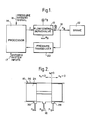
- Figure 1 is a block schematic diagram of a portion of an aircraft braking system, indicating the operation of the invention in controlling the pressure of fluid supplied to a single brake
- Figure 2 is a diagrammatic cross-section through a flow control valve.
- a pressure source P S and a pressure reservoir P R are connected to a flow control servo valve 10.
- the flow of fluid (at a rate ) to a brake 12 is controlled by a signal (electrical current I) from a digital electronic processor 14 which is arranged to receive a pressure demand signal 16 from a pilot-operated control (not shown) and an anti-skid signal 17 from a wheel speed sensor (not shown) or associated skid-control system.
- An output line 18 through which brake operating fluid is supplied from the flow control valve 10 is provided with a pressure transducer 20, connected to the line 18 adjacent to the valve 10 which transmits to the processor 14 a signal proportional to the pressure of brake fluid supplied by the valve 10.
- the rate of flow ( ) of fluid between the valve 10 and the brake 12 is a function of the input current I, the pressure of fluid at source P S , the reservoir pressure P R and the pressure P B in the line to the brake.
- the valve 10 has an effective orifice which has a linear relationship with the input signal I.
- a suitable flow control valve of a type which is well-known in hydraulic systems, comprises a spool 24 which is movable in a cylinder 26 by a servo system (not system), under the control of a torque motor (not shown) through which the input current signal I is passed.
- An orifice 28 is progressively uncovered by the spool 24 when it moves to the right (Fig. 2) as the current I increases, and the effective size of the orifice is proportional to the distance x s moved by the spool along the cylinder from the mean position where the orifice is just fully closed.
- the effective area of either the orifice 28 or the orifice 30 is equal to w. x s where w is the valve orifice area gradient, and x s is the spool displacement.
- the processor 14 can be programmed to operate the valve 10 so as to cut off the supply of fluid from the line 18 when the quantity V (as determined in the processor 14 by integration with respect to time of the values of derived from equations (1) and (2) above) exceeds a predetermined value and thus indicates a leakage in the brake or its connecting line 18.
Landscapes
- Engineering & Computer Science (AREA)
- Mechanical Engineering (AREA)
- Aviation & Aerospace Engineering (AREA)
- Regulating Braking Force (AREA)
- Servomotors (AREA)
- Valves And Accessory Devices For Braking Systems (AREA)
Applications Claiming Priority (2)
| Application Number | Priority Date | Filing Date | Title |
|---|---|---|---|
| GB868625604A GB8625604D0 (en) | 1986-10-25 | 1986-10-25 | Hydraulic systems |
| GB8625604 | 1986-10-25 |
Publications (2)
| Publication Number | Publication Date |
|---|---|
| EP0265761A2 true EP0265761A2 (fr) | 1988-05-04 |
| EP0265761A3 EP0265761A3 (fr) | 1989-05-31 |
Family
ID=10606340
Family Applications (1)
| Application Number | Title | Priority Date | Filing Date |
|---|---|---|---|
| EP87114895A Withdrawn EP0265761A3 (fr) | 1986-10-25 | 1987-10-13 | Circuit hydraulique |
Country Status (4)
| Country | Link |
|---|---|
| US (1) | US4775195A (fr) |
| EP (1) | EP0265761A3 (fr) |
| JP (1) | JPS63116968A (fr) |
| GB (2) | GB8625604D0 (fr) |
Cited By (5)
| Publication number | Priority date | Publication date | Assignee | Title |
|---|---|---|---|---|
| FR2628693A1 (fr) * | 1988-03-18 | 1989-09-22 | Teves Gmbh Alfred | Systeme de freinage a regulation du glissement et a modelisation de la pression de modulateur |
| US5127713A (en) * | 1987-12-12 | 1992-07-07 | Alfred Teves Gmbh | Anti-lock brake system for automotive vehicles |
| GB2510634A (en) * | 2013-02-12 | 2014-08-13 | Ge Aviat Systems Ltd | Methods of monitoring hydraulic fluid levels in an aircraft |
| GB2570500A (en) * | 2018-01-29 | 2019-07-31 | Airbus Operations Ltd | Aircraft hydraulic system |
| WO2021074045A1 (fr) * | 2019-10-15 | 2021-04-22 | Airbus Operations Limited | Procédé d'élimination de fluide hydraulique d'un système hydraulique d'aéronef, système hydraulique d'aéronef et aéronef |
Families Citing this family (6)
| Publication number | Priority date | Publication date | Assignee | Title |
|---|---|---|---|---|
| GB2225397A (en) * | 1988-11-09 | 1990-05-30 | Automotive Products Plc | Electrical control of braking |
| GB2245038B (en) * | 1990-06-07 | 1994-03-23 | Toyota Motor Co Ltd | Device for detecting accumulator fluid leakage through control valve and restoring proper valve seating |
| US5067778A (en) * | 1990-11-19 | 1991-11-26 | Testardi David A | High performance anti-lock brake system for original equipment and after-market applications |
| GB9215510D0 (en) * | 1992-07-22 | 1992-09-02 | Grau Ltd | Braking systems |
| GB2416009A (en) * | 2004-05-12 | 2006-01-11 | Dunlop Aerospace Ltd | Hydraulic fluid control apparatus |
| US12055960B2 (en) * | 2022-03-23 | 2024-08-06 | General Electric Company | Split valves for regulating fluid flow in closed loop systems |
Family Cites Families (7)
| Publication number | Priority date | Publication date | Assignee | Title |
|---|---|---|---|---|
| US3509528A (en) * | 1966-08-08 | 1970-04-28 | Motorola Inc | Warning device for a dual brake system |
| US3671082A (en) * | 1970-03-04 | 1972-06-20 | Bertea Corp | Antiskid system |
| US3667285A (en) * | 1970-08-18 | 1972-06-06 | Customline Control Products In | Leak detection system |
| DE2523600A1 (de) * | 1975-05-28 | 1976-12-09 | Bosch Gmbh Robert | Elektrohydraulische steuereinrichtung |
| CA1151979A (fr) * | 1978-06-01 | 1983-08-16 | Reiner C. Onken | Entrainement regulateur electrohydraulique, et robinet a solenoide a action instantanee connexe |
| US4502501A (en) * | 1983-06-14 | 1985-03-05 | S.N.E.C.M.A. | Fuel control assembly incorporating an integral pressure drop monitor for use with a gas turbine plant |
| BE903722A (fr) * | 1985-11-27 | 1986-03-14 | Lambert Marcel R V | Procede et dispositif de protection d'un circuit hydraulique sous pression a l'encontre d'un epanchement du fluide hydraulique en cas de rupture dans ce circuit. |
-
1986
- 1986-10-25 GB GB868625604A patent/GB8625604D0/en active Pending
-
1987
- 1987-10-12 GB GB8723914A patent/GB2196710B/en not_active Expired - Lifetime
- 1987-10-13 EP EP87114895A patent/EP0265761A3/fr not_active Withdrawn
- 1987-10-13 US US07/107,416 patent/US4775195A/en not_active Expired - Fee Related
- 1987-10-23 JP JP62268036A patent/JPS63116968A/ja active Pending
Cited By (10)
| Publication number | Priority date | Publication date | Assignee | Title |
|---|---|---|---|---|
| US5127713A (en) * | 1987-12-12 | 1992-07-07 | Alfred Teves Gmbh | Anti-lock brake system for automotive vehicles |
| FR2628693A1 (fr) * | 1988-03-18 | 1989-09-22 | Teves Gmbh Alfred | Systeme de freinage a regulation du glissement et a modelisation de la pression de modulateur |
| GB2510634A (en) * | 2013-02-12 | 2014-08-13 | Ge Aviat Systems Ltd | Methods of monitoring hydraulic fluid levels in an aircraft |
| GB2510634B (en) * | 2013-02-12 | 2015-03-04 | Ge Aviat Systems Ltd | Methods of monitoring hydraulic fluid levels in an aircraft |
| US9316520B2 (en) | 2013-02-12 | 2016-04-19 | Ge Aviation Systems Limited | Methods of monitoring hydraulic fluid levels in an aircraft |
| GB2570500A (en) * | 2018-01-29 | 2019-07-31 | Airbus Operations Ltd | Aircraft hydraulic system |
| GB2570500B (en) * | 2018-01-29 | 2020-04-22 | Airbus Operations Ltd | Aircraft hydraulic system |
| US11021237B2 (en) | 2018-01-29 | 2021-06-01 | Airbus Operations Limited | Aircraft hydraulic system |
| WO2021074045A1 (fr) * | 2019-10-15 | 2021-04-22 | Airbus Operations Limited | Procédé d'élimination de fluide hydraulique d'un système hydraulique d'aéronef, système hydraulique d'aéronef et aéronef |
| US11867206B2 (en) | 2019-10-15 | 2024-01-09 | Airbus Operations Limited | Method of removing hydraulic fluid from an aircraft hydraulic system, an aircraft hydraulic system, and an aircraft |
Also Published As
| Publication number | Publication date |
|---|---|
| US4775195A (en) | 1988-10-04 |
| EP0265761A3 (fr) | 1989-05-31 |
| GB8723914D0 (en) | 1987-11-18 |
| GB8625604D0 (en) | 1986-11-26 |
| GB2196710A (en) | 1988-05-05 |
| JPS63116968A (ja) | 1988-05-21 |
| GB2196710B (en) | 1990-02-07 |
Similar Documents
| Publication | Publication Date | Title |
|---|---|---|
| EP0265761A2 (fr) | Circuit hydraulique | |
| US4865399A (en) | Vehicle anti-lock brake system | |
| US4668023A (en) | Control valve for an anti-lock brake system | |
| ES8303624A1 (es) | Aparato para dirigir la circulacion de un fluido. | |
| GB1439293A (en) | Powered brake system for vehicles | |
| US3922021A (en) | Hydraulic skid control system embodying regulator | |
| EP0305877B1 (fr) | Dispositif utilisé dans une direction assistée | |
| US3936095A (en) | Fail safe indicator for skid control system | |
| US4930845A (en) | Process and circuit configuration for controlling a brake system with sequential brake pressure modulation | |
| US3981543A (en) | Skid control system embodying fail safe bypass | |
| EP0218823B1 (fr) | Soupape antipatinage pour système de freinage assisté | |
| US5152589A (en) | Brake slip-controlled hydraulic brake system, especially for use with automotive vehicles | |
| EP0042682A1 (fr) | Système hydraulique et véhicule comportant ledit système | |
| US4575160A (en) | Vehicle wheel controlled anti-brake lock braking arrangement | |
| US3480336A (en) | Hydraulic actuated skid control device | |
| GB1591166A (en) | Anti-skid vehicle braking systems | |
| US3963276A (en) | Skid control system embodying fail safe bypass | |
| GB1385638A (en) | Hydraulic brake control assembly | |
| US4154257A (en) | Flow-divider regulator | |
| US4496192A (en) | Pressure medium brake system | |
| US5588719A (en) | Anti-wheel-lock braking system for a motor vehicle | |
| US4141595A (en) | Anti-wheel-lock or anti-skid system for motor vehicles | |
| WO1993009012A1 (fr) | Systeme de frein electohydraulique | |
| US4181373A (en) | Hydraulic actuator for a motor vehicle anti-skid braking system | |
| US3667497A (en) | Hydraulic systems |
Legal Events
| Date | Code | Title | Description |
|---|---|---|---|
| PUAI | Public reference made under article 153(3) epc to a published international application that has entered the european phase |
Free format text: ORIGINAL CODE: 0009012 |
|
| AK | Designated contracting states |
Kind code of ref document: A2 Designated state(s): DE FR IT NL |
|
| PUAL | Search report despatched |
Free format text: ORIGINAL CODE: 0009013 |
|
| AK | Designated contracting states |
Kind code of ref document: A3 Designated state(s): DE FR IT NL |
|
| 17P | Request for examination filed |
Effective date: 19890826 |
|
| 17Q | First examination report despatched |
Effective date: 19900801 |
|
| STAA | Information on the status of an ep patent application or granted ep patent |
Free format text: STATUS: THE APPLICATION IS DEEMED TO BE WITHDRAWN |
|
| 18D | Application deemed to be withdrawn |
Effective date: 19910615 |
|
| RIN1 | Information on inventor provided before grant (corrected) |
Inventor name: MILLER, RICHARD JOHN |