EP0265896A2 - Support pour disque de stockage de données - Google Patents
Support pour disque de stockage de données Download PDFInfo
- Publication number
- EP0265896A2 EP0265896A2 EP87115706A EP87115706A EP0265896A2 EP 0265896 A2 EP0265896 A2 EP 0265896A2 EP 87115706 A EP87115706 A EP 87115706A EP 87115706 A EP87115706 A EP 87115706A EP 0265896 A2 EP0265896 A2 EP 0265896A2
- Authority
- EP
- European Patent Office
- Prior art keywords
- disk
- carrier
- frame
- latching
- periphery
- Prior art date
- Legal status (The legal status is an assumption and is not a legal conclusion. Google has not performed a legal analysis and makes no representation as to the accuracy of the status listed.)
- Withdrawn
Links
Images


Classifications
-
- G—PHYSICS
- G11—INFORMATION STORAGE
- G11B—INFORMATION STORAGE BASED ON RELATIVE MOVEMENT BETWEEN RECORD CARRIER AND TRANSDUCER
- G11B17/00—Guiding record carriers not specifically of filamentary or web form, or of supports therefor
- G11B17/02—Details
- G11B17/04—Feeding or guiding single record carrier to or from transducer unit
- G11B17/041—Feeding or guiding single record carrier to or from transducer unit specially adapted for discs contained within cartridges
- G11B17/049—Insertion of discs having to be extracted from the cartridge prior to recording or reproducing
-
- G—PHYSICS
- G11—INFORMATION STORAGE
- G11B—INFORMATION STORAGE BASED ON RELATIVE MOVEMENT BETWEEN RECORD CARRIER AND TRANSDUCER
- G11B23/00—Record carriers not specific to the method of recording or reproducing; Accessories, e.g. containers, specially adapted for co-operation with the recording or reproducing apparatus ; Intermediate mediums; Apparatus or processes specially adapted for their manufacture
- G11B23/02—Containers; Storing means both adapted to cooperate with the recording or reproducing means
- G11B23/03—Containers for flat record carriers
- G11B23/0301—Details
- G11B23/0313—Container cases
- G11B23/0316—Constructional details, e.g. shape
-
- G—PHYSICS
- G11—INFORMATION STORAGE
- G11B—INFORMATION STORAGE BASED ON RELATIVE MOVEMENT BETWEEN RECORD CARRIER AND TRANSDUCER
- G11B23/00—Record carriers not specific to the method of recording or reproducing; Accessories, e.g. containers, specially adapted for co-operation with the recording or reproducing apparatus ; Intermediate mediums; Apparatus or processes specially adapted for their manufacture
- G11B23/02—Containers; Storing means both adapted to cooperate with the recording or reproducing means
- G11B23/03—Containers for flat record carriers
- G11B23/0328—Containers for flat record carriers the disc having to be extracted from the cartridge for recording reproducing, e.g. cooperating with an extractable tray
Definitions
- This invention relates to the field of data recording/playback and, more particularly, to apparatus for facilitating the handling and transport of data storage disks, e.g. optical and magnetic hard disks.
- Such a cartridge includes a plurality of spring-loaded latches which engage the enclosed disk at spaced locations about the disk periphery.
- Such latches are intended to precisely locate the disk within the cartridge so that it may be reliably positioned relative to a rotatable spindle in a disk drive, and to prevent the disk from shifting laterally or axially within the cartridge and thereby contacting the cartridge walls.
- tapered pins associated with the disk drive unit, are moved in a direction to engage and release the spring-loaded latches, displacing such latches to a position which permits unimpeded disk rotation.
- the disk drive unit comprises a mechanism for entering the disk's protective jacket and physically gripping the disk so that when the jacket is withdrawn from the disk drive unit, the disk is retained within the drive unit.
- the periphery is provided with a raised bead which can be more readily engaged.
- Such a device typically comprises a rigid, planar frame, often generally rectangular in shape, having a circular aperture slightly larger in diameter than that of the disk.
- a plurality of radially extending tabs extend inwardly from the aperture wall and support the disk at spaced locations around the disk periphery. See, for example, the disk carriers disclosed in U.S. Patent Nos. 4,419,060 and 4,481,617.
- Such disk carriers are normally totally enclosed by a protective caddy, and removal of the disk from the caddy is achieved by engaging and withdrawing the disk carrier.
- disk carriers of the above type there is, by necessity, a relatively loose fit between the disk and the disk-capturing features of the carrier. This loose fit is necessitated by the fact that the disk is intended to rotate within the carrier frame.
- the carrier is precisely located relative to a disk drive spindle so that the disk can be rotatably driven without contacting any of the carrier's disk-capturing features.
- the disk must have a certain amount of freedom to move both axially and laterally within the carrier frame. Such freedom of movement is potentially harmful to a captured disk, particularly to those disks of a more fragile nature.
- such carriers cannot precisely locate their captured disk relative to the axis of rotation of a drive spindle.
- the lateral position of the disk can vary substantially, due to its freedom to move within the carrier frame.
- the disk drive unit must be capable of accepting a disk which is substantially displaced from a desired axis of rotation.
- an object of this invention is to provide an improved carrier for a data storage disk, a carrier which is improved from the standpoint that it is capable of securely capturing the disk in a precise position relative to the carrier's structure, yet is capable of readily releasing the disk for use at a location substantially spaced from the carrier.
- Another object of this invention is to provide an improved disk carrier in which certain features for releasing the disk from a securely captured position are arranged so as to have two axes of symmetry, whereby the disk carrier can be inserted into the disk drive in any one of four different orientations.
- Another object of this invention is to provide an improved disk carrier which is capable of releasing a securely captured disk without substantial displacement of the disk.
- the disk carrier of the invention comprises a planar frame having a wall defining a circular aperture for receiving a data storage disk, the diameter of the aperture being slightly greater than the disk diameter, and means for retaining the disk within such aperture so that the disk and frame are substantially coplanar.
- retaining means comprises disk support means extending rigidly from the aperture wall of the carrier for supporting a disk received within the aperture and urged into contact therewith; and releasable latching means movably mounted on the carrier frame for selectively engaging a disk located in the carrier aperture and for urging such disk into engagement with the disk support means.
- the carrier frame is Provided with structure which is engagable by a disk-releasing mechanism associated with a disk drive unit for shifting the position of the carrier in a direction to release the disk from the disk support means while such disk-releasing mechanism operates to move the latching means to a non-latching position, out of engagement with a disk, whereby the disk is freed from the carrier without substantially altering the position of the disk.
- a disk-releasing mechanism associated with a disk drive unit for shifting the position of the carrier in a direction to release the disk from the disk support means while such disk-releasing mechanism operates to move the latching means to a non-latching position, out of engagement with a disk, whereby the disk is freed from the carrier without substantially altering the position of the disk.
- such disk retaining means and disk-releasing structure are arranged on the carrier so as to be engagable by the disk-releasing mechanism, regardless of which of four different orientations the disk is presented to the release mechanism.
- FIG. 1 illustrates a data recording/playback system comprising a disk drive unit 2 and a data storage disk assembly 4.
- the latter basically comprises a rigid data storage disk 6, a disk carrier 8 and a protective caddy 10.
- disk carrier 8 serves to releasably capture disk 6 so that the disk is accurately and securely registered within the carrier structure, yet is capable of being readily removed from the carrier for rotation in a plane spaced from the carrier.
- the carrier and its captured disk are positioned within the protective caddy, the latter being sufficiently rigid to guard against contact with the disk's recording surfaces.
- the carrier-loaded caddy is inserted into the disk drive unit through a door 2a.
- a mechanism within serves to extract the disk carrier from the caddy and to return the caddy to the user.
- the disk drive unit also includes apparatus for releasing the disk from its carrier and for loading the disk onto a drive spindle assembly for rotation. Such apparatus is disclosed in detail in the commonly assigned U.S. Application No. 923,508, filed concurrently herewith in the name of Dwight Petruchik, and only those elements which cooperate directly with the disk carrier of the invention are described herein.
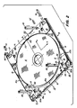
- carrier 8 is shown to comprise a planar frame 12 having a wall portion 12a which defines a generally circular aperture 13 for receiving the rigid data storage disk 6.
- the diameter of aperture 13 is slightly larger than the disk diameter to readily accomodate the disk.
- the generally circular aperture 13 has four expanded regions 13a which accomodate certain disk supporting members (not shown) of the disk drive unit which serve to support the disk upon release from the carrier.
- the carrier frame is also provided with certain cutouts C and notches N in its leading and trailing edges (as determined by the direction in which the carrier is inserted into the disk drive unit) which cooperate with a carrier locating mechanism (M, M ⁇ ) within the disk drive unit for precisely locating the carrier with respect to a desired axis of rotation.
- a carrier locating mechanism M, M ⁇
- frame 12 comprise various discrete elements which are mechanically coupled to provide the frame configuration shown.
- Such elements may comprise, for example, a pair of opposing side rails 14, 15 and end members 16, 17, all of which can be made of plastic (e.g. polycarbonate) and injection molded to produce the shapes shown.
- a plurality of sheet metal plates 18, e.g. made of aluminum, and suitable fasteners 19 serve to connect elements 14-17 in the manner shown.
- carrier 8 comprises disk retention means for accurately positioning and releasably capturing a disk within the plane of the carrier frame.
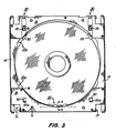
- Such disk retention means comprises disk support means 20 for engaging and supporting a disk which is urged into contact therewith at a first location (A) along the disk periphery, and releasable latching means 30 which is adapted to selectively engage a disk at one or more other locations (B) along the disk periphery and to urge such disk into engagement with the support means 20.
- disk support means 20 comprises a plurality of stationary support tabs 22 which are mounted on, and extend angularly from, the aperture-defining frame wall 12a. Such tabs, as best shown in FIG. 4, cooperate in supporting a disk, when urged into engagement therewith, from both sides.
- tabs 22 support the disk periphery over a relatively short angular arc of approximately 15°. The length of such arc is a trade-off between providing a secure support, and facilitating release of the disk without substantial displacement of the carrier frame, as described below.
- the tabs 22 are integral with wall 12a, being formed by the injection molding process used to fabricate the carrier frame's leading end element 17.
- Releasable latching means 30 preferably comprises a pair of movable latching members 32 which are slidably mounted in slots 33 defined by the carrier frame elements for movement in a direction which is generally perpendicular to the tangent T at point A of the disk periphery, i.e. the midpoint of the arc over which support means 20 provides support.
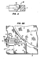
- Each latching member as shown in FIGS. 5A and 5B, has a V-shaped latching edge 32a which is arcuately contoured to the shape of the disk periphery and serves to support an engaged disk from both sides. Both of the opposing lateral edges latching member 32 is provided with an integral pad 34 which facilitate sliding movement in slots 33.
- each member 32 has a rectangular opening 35 having a chamfered edge 35a which is adapted to be engaged by the tapered edge 40a of a movable skewer 40 (associated with a disk-release mechanism disclosed in the aforementioned U.S. Application) for the purpose of urging the latching member in a direction to unlatch and release the disk.
- a compression spring 36 which, in cooperation with certain carrier frame structure, biases the latching member 32 in the direction perpendicular to tangent T, towards a latching position in which edge 32a is in engagement with the disk periphery.
- Spring 36 is supported on member 32 by a limb 38 which extends into a slot 37 formed in the interior of member 32.
- latching member 32 is slidably mounted in slot 33, defined by the spaced parallel edges 14a and 16a of frame elements 14 and 16, respectively. As indicated above, elements 14 and 16 are connected by a pair of opposing plates 18 which span members 14 and 16 on both sides of the carrier frame.
- latching member 32 is shown in a latching position in which the arcuate, V-shaped latching edge 32a is engaged with the peripheral edge 6a of disk 6.
- Latching member 32 is maintained in this position by the biasing force provided by compression spring 36, one end of such spring engaging the forward end of slot 37 in latching member 32, and the other end being engaged by a pair of opposing bosses 18a extending into slot 33 from plates 18.
- Access to the latching member's rectangular aperture 35 by skewer 40 is had through slightly larger rectangular apertures 18b formed in the opposing carrier plates 18.
- a stop member 16b is provided on carrier frame element 16. Such stop member cooperates with one of the sliding pads 34 to limit the forward movement of member 32.
- carrier 8 Also to be noted in the design of carrier 8 is the fact that the spring latches function to urge the disk against a fixed disk support. By this arrangement, the disk can be precisely and repeatedly positioned in the carrier frame.
- This arrangement is to be contrasted with that disclosed in the aforementioned U.S Patent No. 4,433,410 in which the disk is supported by a plurality of spring-biased latches all of which apply radially directed forces.
- the spring force of each latch is pitted against the forces of all the other latches and, as the spring forces vary with time, the disk position shifts within the supporting cartridge.
- each latch is mounted for movement in a radial direction and, since the restoring force emanates at the center of the disk, the unlatching force is resisted primarily by the bearing springs.
- movement of the latching members in the carrier of the invention move in a non-radial direction, preferably perpendicular to tangent T of the midpoint of disk support 20.
- the restoring forces act at an angle relative to the edges slot 33, and the thusly enhanced friction between the latching member 34 and slot edge 14a supplements the spring force in resisting the unlatching movement of the latch.
- this arrangement reduces the tolerances required in fabricating the latch slot 33.
- carrier frame element 17 there are provided two rectangular openings 50 which are aligned with the unlatching, rectangular apertures 35 of latching members 31. As arranged, the rectangular openings 50 and 35 define a rectangular pattern. Like apertures 35, the rectangular apertures 50 are provided with a chamfered edge 50a which is adapted to be engaged by the caming surface of a disk release mechanism of the disk drive unit. Referring to FIG.
- the latching members are moved to an unlatching position, as described above, and simultaneously therewith the carrier frame is moved in an opposite direction to free the disk periphery from engagement with the disk support means 20.
- the disk is simultaneously freed from all support provided by the carrier, and the disk is thereby released without any substantial displacement in the X direction.
- the four disk releasing skewers of the disk drive unit can operate on the disk carrier to release the disk therefrom no matter which of the four different orientations the carrier can be inserted, and accurately positioned in the disk drive unit.
- the carrier may enter the disk drive unit in the orientation shown in FIG. 2, or in an upside down orientation derived by rotating the carrier 180° about the X axis, or in either of these orientations after the carrier has been similarly rotated about the Y axis.
- a substantially improved disk carrier Owing to the combination of fixed and movable retainers, a disk can be precisely located within the carrier and, hence, within the disk drive unit. Owing to the placement of the movable latches and apertures 50, a disk can be released from the carrier in four different orientations using the same disk releasing mechanisms, and the disk position is not substantially altered during release from the carrier. Moreover, by dimensioning the latches so that its non-latching end is coplanar with a carrier within a caddy, is substantially contiguous with an interior wall of the caddy, the chance for inadvertent release of the disk from the carrier can be reduced.
Landscapes
- Automatic Disk Changers (AREA)
- Moulds For Moulding Plastics Or The Like (AREA)
Applications Claiming Priority (2)
| Application Number | Priority Date | Filing Date | Title |
|---|---|---|---|
| US923509 | 1986-10-27 | ||
| US06/923,509 US4773061A (en) | 1986-10-27 | 1986-10-27 | Carrier for data storage disk |
Publications (2)
| Publication Number | Publication Date |
|---|---|
| EP0265896A2 true EP0265896A2 (fr) | 1988-05-04 |
| EP0265896A3 EP0265896A3 (fr) | 1989-07-26 |
Family
ID=25448805
Family Applications (1)
| Application Number | Title | Priority Date | Filing Date |
|---|---|---|---|
| EP87115706A Withdrawn EP0265896A3 (fr) | 1986-10-27 | 1987-10-27 | Support pour disque de stockage de données |
Country Status (5)
| Country | Link |
|---|---|
| US (1) | US4773061A (fr) |
| EP (1) | EP0265896A3 (fr) |
| JP (1) | JPH0632181B2 (fr) |
| AU (1) | AU8016087A (fr) |
| CA (1) | CA1302561C (fr) |
Cited By (5)
| Publication number | Priority date | Publication date | Assignee | Title |
|---|---|---|---|---|
| EP0351160A3 (en) * | 1988-07-11 | 1990-03-07 | Minnesota Mining And Manufacturing Company | Disk restraint |
| EP0384525A1 (fr) * | 1989-02-23 | 1990-08-29 | Koninklijke Philips Electronics N.V. | Support pour un disque pouvant être enregistré et/ou lu |
| DE19543943A1 (de) * | 1995-03-17 | 1996-09-19 | Fujitsu Ltd | Träger für eine optische Platte |
| EP0862174A1 (fr) * | 1997-02-27 | 1998-09-02 | Lite-On Technology Corp. | Dispositif de changement de disque pour lecteur de disque optique |
| RU2190259C2 (ru) * | 1998-07-15 | 2002-09-27 | Самсунг Электроникс Ко., Лтд. | Адаптер для размещения диска |
Families Citing this family (19)
| Publication number | Priority date | Publication date | Assignee | Title |
|---|---|---|---|---|
| US4849959A (en) * | 1988-06-16 | 1989-07-18 | Eastman Kodak Company | Split disk carrier with locking mechanism |
| DE3923107C2 (de) * | 1989-07-13 | 1998-04-16 | Thomson Brandt Gmbh | Aufnahmevorrichtung für einen scheibenförmigen Informationsträger |
| US5205496A (en) * | 1991-06-05 | 1993-04-27 | O.D.E. Investments Corporation | Universal grinder with reciprocal feeder |
| US5383554A (en) * | 1991-06-11 | 1995-01-24 | Cowan; David M. | Container for storing and displaying an article |
| KR950005920Y1 (ko) * | 1993-06-30 | 1995-07-26 | 대우전자 주식회사 | 데이터 메모리용 드로우 타입 트레이의 미니디스크 고정장치 |
| USD387907S (en) * | 1995-10-23 | 1997-12-23 | Vandigriff John E | Combined container for computer software and manuals |
| US6529471B1 (en) * | 1998-07-15 | 2003-03-04 | Lg Electronics Inc. | Disc protection casing and drive for receiving the same |
| US6024214A (en) * | 1999-02-22 | 2000-02-15 | Cowan; David M. | Container for storing and displaying an article |
| WO2001011624A1 (fr) * | 1999-08-04 | 2001-02-15 | Atop Innovation Spa | Memoire de masse amelioree |
| EP1200958A1 (fr) * | 1999-08-04 | 2002-05-02 | Atop Innovation SPA | Memoire de masse amelioree |
| US6583951B1 (en) * | 1999-11-12 | 2003-06-24 | Terastor Corporation | Shuttle motion mechanism |
| EP1363288B8 (fr) * | 2001-01-12 | 2009-08-12 | Panasonic Corporation | Cartouche de disque |
| US6910219B2 (en) * | 2001-07-06 | 2005-06-21 | Matsushita Electric Industrial Co., Ltd. | Disc cartridge |
| JP3891984B2 (ja) * | 2001-11-09 | 2007-03-14 | 松下電器産業株式会社 | ディスクカートリッジ |
| JP2003242740A (ja) * | 2002-02-15 | 2003-08-29 | Matsushita Electric Ind Co Ltd | ディスクカートリッジ |
| JP3891906B2 (ja) * | 2002-03-08 | 2007-03-14 | 松下電器産業株式会社 | ディスクカートリッジ |
| CN1578934A (zh) * | 2002-08-30 | 2005-02-09 | 精工爱普生株式会社 | 模拟电子表 |
| FR2846775B1 (fr) * | 2002-11-05 | 2006-11-24 | Francis Laroche | Conditionnement pour un support d'enregistrement numerique en forme de disque |
| EP1629497B1 (fr) * | 2003-04-09 | 2009-07-01 | Panasonic Corporation | Cartouche de disque |
Family Cites Families (16)
| Publication number | Priority date | Publication date | Assignee | Title |
|---|---|---|---|---|
| US4266784A (en) * | 1979-11-28 | 1981-05-12 | Rca Corporation | Video disc caddy having disc entrapment |
| JPS606930Y2 (ja) * | 1981-06-01 | 1985-03-07 | 日本ビクター株式会社 | 円盤状情報記録媒体用カ−トリツジ |
| US4436201A (en) * | 1981-11-11 | 1984-03-13 | Victor Company Of Japan Limited | Disc cartridge having a detachable lid |
| US4433410A (en) * | 1982-06-30 | 1984-02-21 | Rca Corporation | Protective cartridge for optical discs |
| JPS5965978A (ja) * | 1982-09-21 | 1984-04-14 | ゼロツクス・コ−ポレ−シヨン | 光デイスクカ−トリツジ |
| US4481617A (en) * | 1982-09-21 | 1984-11-06 | Xerox Corporation | Memory disc drive |
| CA1228030A (fr) * | 1983-06-15 | 1987-10-13 | Petrus L.A. Rouws | Lecteur de disque comportant un mecanisme de chargement de disque et support de disque utilise dans ce lecteur |
| JPS6050680A (ja) * | 1983-08-29 | 1985-03-20 | Hitachi Ltd | ディスクカ−トリッジ |
| JPS6085479A (ja) * | 1983-10-14 | 1985-05-14 | Hitachi Maxell Ltd | デイスクカ−トリツジ |
| US4707821A (en) * | 1983-11-08 | 1987-11-17 | U.S. Philips Corporation | Disc holder for a rigid audio and/or video disc |
| JPS60224170A (ja) * | 1984-04-20 | 1985-11-08 | Asahi Chem Ind Co Ltd | 光デイスクカセツト |
| NL8401672A (nl) * | 1984-05-25 | 1985-12-16 | Philips Nv | Houder voor een starre informatieplaat alsmede systeem omvattende een dergelijke houder en een daarmee samenwerkend laadmechanisme. |
| KR900006313B1 (ko) * | 1984-07-23 | 1990-08-28 | 마쯔시다덴기산교 가부시기가이샤 | 디스크의 수납트레이 및 그것을 사용한 플레이어 |
| JPS6168782A (ja) * | 1984-09-12 | 1986-04-09 | Sony Corp | デイスクカ−トリツジ |
| JPH0240627Y2 (fr) * | 1984-10-13 | 1990-10-30 | ||
| US4749081A (en) * | 1987-02-27 | 1988-06-07 | Eastman Kodak Company | Carrier for rigid data storage disk |
-
1986
- 1986-10-27 US US06/923,509 patent/US4773061A/en not_active Expired - Fee Related
-
1987
- 1987-09-28 CA CA000548029A patent/CA1302561C/fr not_active Expired - Fee Related
- 1987-10-26 JP JP62270051A patent/JPH0632181B2/ja not_active Expired - Lifetime
- 1987-10-27 AU AU80160/87A patent/AU8016087A/en not_active Abandoned
- 1987-10-27 EP EP87115706A patent/EP0265896A3/fr not_active Withdrawn
Cited By (5)
| Publication number | Priority date | Publication date | Assignee | Title |
|---|---|---|---|---|
| EP0351160A3 (en) * | 1988-07-11 | 1990-03-07 | Minnesota Mining And Manufacturing Company | Disk restraint |
| EP0384525A1 (fr) * | 1989-02-23 | 1990-08-29 | Koninklijke Philips Electronics N.V. | Support pour un disque pouvant être enregistré et/ou lu |
| DE19543943A1 (de) * | 1995-03-17 | 1996-09-19 | Fujitsu Ltd | Träger für eine optische Platte |
| EP0862174A1 (fr) * | 1997-02-27 | 1998-09-02 | Lite-On Technology Corp. | Dispositif de changement de disque pour lecteur de disque optique |
| RU2190259C2 (ru) * | 1998-07-15 | 2002-09-27 | Самсунг Электроникс Ко., Лтд. | Адаптер для размещения диска |
Also Published As
| Publication number | Publication date |
|---|---|
| AU8016087A (en) | 1988-04-28 |
| JPS63113990A (ja) | 1988-05-18 |
| CA1302561C (fr) | 1992-06-02 |
| US4773061A (en) | 1988-09-20 |
| JPH0632181B2 (ja) | 1994-04-27 |
| EP0265896A3 (fr) | 1989-07-26 |
Similar Documents
| Publication | Publication Date | Title |
|---|---|---|
| US4773061A (en) | Carrier for data storage disk | |
| US4817079A (en) | Carrier retainer for disk cartridge | |
| US3951264A (en) | Flexible disc cartridge | |
| US5481420A (en) | Data storage device with removable cartridge having shutter unlocking and disk unrestraining arrangements | |
| US5636095A (en) | Removable disk to drive engagement | |
| PL110306B1 (en) | Video disk recorder | |
| JPH0348592B2 (fr) | ||
| GB2029076A (en) | Locking mechanism for record package | |
| US5140489A (en) | Disk cartridge adapted for use with different disk drives | |
| KR900008097B1 (ko) | 테이프 카세트 | |
| EP0265897A2 (fr) | Système et appareil de manipulation de disques | |
| JPS5965980A (ja) | デイスクドライブ装置 | |
| EP0320897B1 (fr) | Assemblage de disque pour mémoriser des données avec dispositif de sécurité pour empêcher la réécriture | |
| EP0351160B1 (fr) | Dispositif pour retenir un disque | |
| US4736903A (en) | Self-locking hub assembly for a compact audio tape cassette and method for assembly | |
| JPS62273652A (ja) | デイスクカ−トリツジのシヤツタ開閉機構 | |
| EP0228600B1 (fr) | Cassette à bande | |
| US4222487A (en) | Single disk cartridge | |
| NL192994C (nl) | Anti-diefstalinrichting voor compactdiscs. | |
| US4853926A (en) | Split carrier for data storage disks | |
| US4802049A (en) | Disc cartridge | |
| EP0920010B1 (fr) | Cartouche de disque magnetique | |
| US6286776B1 (en) | Magnetic tape cassette | |
| US4849959A (en) | Split disk carrier with locking mechanism | |
| KR0120976Y1 (ko) | 테이프 카세트 |
Legal Events
| Date | Code | Title | Description |
|---|---|---|---|
| PUAI | Public reference made under article 153(3) epc to a published international application that has entered the european phase |
Free format text: ORIGINAL CODE: 0009012 |
|
| AK | Designated contracting states |
Kind code of ref document: A2 Designated state(s): DE FR GB NL |
|
| PUAL | Search report despatched |
Free format text: ORIGINAL CODE: 0009013 |
|
| AK | Designated contracting states |
Kind code of ref document: A3 Designated state(s): DE FR GB NL |
|
| 17P | Request for examination filed |
Effective date: 19900118 |
|
| 17Q | First examination report despatched |
Effective date: 19910320 |
|
| STAA | Information on the status of an ep patent application or granted ep patent |
Free format text: STATUS: THE APPLICATION HAS BEEN WITHDRAWN |
|
| 18W | Application withdrawn |
Withdrawal date: 19920824 |
|
| RIN1 | Information on inventor provided before grant (corrected) |
Inventor name: SEMMLER, BRUCE JOHN Inventor name: PETRUCHIK, DWIGHT JOHN Inventor name: BERNITT, CHARLES JOSEPH Inventor name: STARK, DANIEL JOHN |