EP0265953A2 - Schleifmaschine - Google Patents
Schleifmaschine Download PDFInfo
- Publication number
- EP0265953A2 EP0265953A2 EP87115922A EP87115922A EP0265953A2 EP 0265953 A2 EP0265953 A2 EP 0265953A2 EP 87115922 A EP87115922 A EP 87115922A EP 87115922 A EP87115922 A EP 87115922A EP 0265953 A2 EP0265953 A2 EP 0265953A2
- Authority
- EP
- European Patent Office
- Prior art keywords
- carriage
- wheel slide
- wheel
- grinding wheel
- guideway
- Prior art date
- Legal status (The legal status is an assumption and is not a legal conclusion. Google has not performed a legal analysis and makes no representation as to the accuracy of the status listed.)
- Withdrawn
Links
Images





Classifications
-
- B—PERFORMING OPERATIONS; TRANSPORTING
- B24—GRINDING; POLISHING
- B24B—MACHINES, DEVICES, OR PROCESSES FOR GRINDING OR POLISHING; DRESSING OR CONDITIONING OF ABRADING SURFACES; FEEDING OF GRINDING, POLISHING, OR LAPPING AGENTS
- B24B41/00—Component parts such as frames, beds, carriages, headstocks
- B24B41/02—Frames; Beds; Carriages
Definitions
- the present invention relates to an apparatus for grinding a workpeice and more particularly to the manner in which a wheel slide is supported by a carriage for movement relative to a workpiece.
- a known grinding apparatus has a carriage which is movable along a path extending parallel to the axis of rotation of a workpiece.
- a wheel slide is mounted on the carriage.
- a grinding wheel is rotatable supported on the wheel side. Movement of the wheel slide toward and away from the workpiece moves the grinding wheel into and out of engagement with the workpiece.
- U.S. Patent No. 2,710,494 entitled Grinding Machine, issued June 14, 1955.
- the accurate grinding of a workpiece requires the wheel slide to provide a solid support for the grinding wheel.
- the necessity of having a solid support for the grinding wheel has resulted in a wheel slide being relatively massive so that it cannot be deflected during a grinding operation.
- a massive wheel slide does provide a solid support for a grinding wheel, the massive wheel slide has a relatively large amount of inertia and cannot be quickly and accurately positioned relative to the workpiece.
- the present invention provides a grinding apparatus having a carriage with a plurality of internal guideways which solidly support the wheel slide.
- the solid support provided by the guideways inside the carriage enables a grinding wheel to be supported by a relatively light weight wheel slide. Since the wheel slide is relatively light weight, it can be quickly and accurately positioned relative to a workpiece.
- FIGURE 1 illustrates a grinding apparatus having a base 10 upon which a workpiece support and drive assembly 20 is mounted.
- a carriage 300 is movable horizontally along the base 10 from the position shown in solid lines in FIGURE 1 to the position shown in dashed lines in FIGURE 1.
- a light weight wheel slide 400 supports a grinding wheel assembly 500 for movement toward and away from an axis A about which a workpiece is rotated.
- a wheel slide drive assembly 60 is connected with the carriage 300 and is operable to move the wheel slide 400 vertically relative to the carriage 300.
- the workpiece support and drive assembly 20 includes a headstock 21 which grips one end of a workpiece and is driven by a motor 22 to rotate the workpiece about the horizontal axis A.
- the opposite end of the workpiece is gripped by a footstock 23 to further support the workpiece for rotation about the axis A.
- the grinding wheel assembly 500 includes a grinding wheel 501 which is rotatable about a horizontal axis B.
- the axis B of rotation of the grinding wheel 501 extends parallel to and is vertically aligned with the axis A about which the workpiece is supported and rotated by the headstock 21 and tailstock 23.
- the wheel slide drive assembly 60 includes a reversible motor 61 which is connected with a vertically extending drive screw 62.
- the central axis of the drive screw 62 is located in a vertical plane which contains the axis A of rotation of the workpiece and the axis B of rotation of the grinding wheel 501. Operation of the motor 61 rotates the drive screw 62 to either raise or lower the wheel slide 400 and grinding wheel assembly 500 relative to the axis A of rotation of the workpiece.
- the carriage 300 is movable along a horizontal path extending parallel to the axis A of rotation of the workpiece to position the grinding wheel 501 relative to the workpiece.
- FIGURE 2 illustrates a carriage drive assembly 70 which is connected with the carriage 300 and is operable to move the carriage along parallel horizontal guideways 11 and 12 disposed on the base 10.
- the carriage drive assembly 70 includes a reversible motor 71 which is mounted on the base 10 and is connected with the carriage 300 by a horizontal drive screw 72.
- the guideways 11 and 12 on the base 10 have horizontal central axes C and D which extend parallel to a horizontal central axis E of the carriage drive screw 72.
- Operation of the motor 71 in one direction rotates the drive screw 72 to move the carriage 300 leftward, as viewed in FIGURE 2, to a position in which the carriage partially encloses the headstock 21.
- Operation of the motor 71 in the opposite direction rotates the drive screw 72 to move the carriage 300 rightward, as viewed in FIGURE 2, to a position in which the carriage 300 encloses the footstock 23.
- a grinding wheel drive assembly 800 is mounted on the carriage 300 and is connected with the grinding wheel assembly 500.
- the grinding wheel drive assembly 800 includes a motor 801 which is pivotally connected to a bracket 802 fixed to the carriage 300.
- a motor output shaft 803 is rotatable during operation of the motor 801 to drive a belt 804 connected with the grinding wheel assembly 500.
- the grinding wheel 501 is rotated about the axis B to grind the workpiece as it rotates about the axis A. Since the grinding wheel drive assembly 800 is mounted on the carriage 300, the weight of the grinding wheel drive assembly does not add to the weight which must be moved with the wheel slide 400.
- the axes C and D of the ways 11 and 12 are disposed in a single horizontal plane.
- the horizontal plane containing the axes C and D is intersected by a vertical plane containing the axis A and B of rotation of the workpiece and grinding wheel at a location midway between the guideway axes C and D.
- the guideway axes C and D extend parallel to the axes A and B of rotation of the workpiece and grinding wheel.
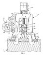
- Figure 3 further illustrates the construction of the carriage 300 which extends upwardly from the base 10.
- the carriage 300 has a pair of vertical legs 301 and 302 which are interconnected by a horizontal connector section 303.
- the legs 301 and 302 and connector section 303 result in the carriage 300 having an upside-down U-shaped cross sectional configuration in a vertical plane extending perpendicular to the horizontal axis of rotation of the workpiece W.
- the legs 301 and 302 flare outwardly at their lower end portions to increase the stability of the carriage 300.
- the carriage 300 is supported on the horizontal guideways 11 and 12 which are disposed on opposite sides of the axis of rotation of the workpiece W and extend parallel to the axis of rotation of the workpiece.
- the guideways 11 and 12 are each disposed the same distance from a vertical plane which contains the axes of rotation of the workpiece W and grinding wheel 501 and extends through the center of the connector section 303. Since the carriage 300 spans the work area where operating forces are generated by engagement of the grinding wheel 501 with the workpiece W, operating forces are transmitted in a balanced manner by the vertical carriage legs 301 and 302 to the guideways 11 and 12.
- the wheel slide 400 is movable along a vertical path extending perpendicular to the axis of rotation of the workpiece W by operation of the drive assembly 60.
- the wheel slide drive assembly 60 includes the motor 61 which is mounted on the connector section 303 of the carriage 300.
- the motor 61 is connected with the vertical drive screw 62 through a coupling 63.
- the drive screw 62 is itself connected with the wheel slide 400.
- the axis of rotation of the drive screw 62 extends perpendicular to the axis of rotation of the workpiece W and is disposed in a vertical plane containing the axis of rotation of the workpiece W and the axis of rotation of the grinding wheel 501.
- the grinding wheel drive assembly 800 includes the motor 801 which is mounted on a base 805 which is pivotally connected at 806 with the bracket 802.
- the bracket 802 is fixedly connected to the leg 301 of the carriage 300.
- a biasing spring assembly 808 is connected with the base 805 and urges the base to rotate in a clockwise direction (as viewed in FIGURE 3) about the pivot connection 806. Therefore, the spring assembly 808 maintains the belt 8-4 tight around a pulley 809 connected with the output shaft 803 of the motor 801.
- the grinding wheel 501 moves either toward or away from the axis of rotation of the output shaft 803 of the motor 801.
- the spring assembly 808 urges the base 805 to pivot outwardly away from the leg 301 of the carriage 300 to maintain the belt 804 tight around the pulley 809.
- the belt 804 pulls the motor 801 and base 805 in a counter-clockwise direction about the pivot connection 806 to contract the spring assembly 808.
- the spring assembly 808 is effective to maintain a substantially constant spring force against the base 805 throughout the normal range of movement of the base 805 relative to the carriage 300. Since the length of the belt 804 does not change, the distance between the axis of rotation of the grinding wheel 501 and the axis of rotation of the motor shaft 803 remains constant during movement of the wheel slide 400.
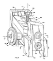
- FIGURE 4 is a broken away schematic illustration depicting the manner in which the light weight wheel slide 400 is enclosed by vertical guideways 900 located within the carriage 300.
- the guideways 900 include a relatively large main or double guideway 901 and a pair of smaller secondary or single guideways 902 and 903.
- the main guideway 901 cooperates with a relatively large rectangular main section 401 of the wheel slide 400.
- the secondary guideways 902 and 903 cooperate with both the main section 401 and a rectangular secondary section 402 of the wheel slide 400 to guide vertical movement of the wheel slide upon rotation of the drive screw 62.
- the main guideway 901 is located on one side, that is the left side as viewed parallel to the grinding wheel axis 3 in FIGURE 4, of a vertical plane containing the axis of rotation B of the grinding wheel 501 and the axis of rotation F of the drive screw 62.
- the guideways 902 and 903 are located on the opposite side, that is the right side as viewed in FIGURE 4, of the vertical plane containing the orthonogal grinding wheel and drive screw axes B and F.
- the guideways 901, 902 and 903 are disposed within the carriage 300 and are enclosed by the carriage throughout the vertical length of the guideways. This results in a relatively solid support for the guideways 901, 902 and 903 so that the guideways provide a very solid mounting for the wheel slide 400.
- the solid support provided for the wheel slide 400 by the guideways 901, 902 and 903 enables the wheel slide to be relatively light weight so that it has a relatively small amount of inertia and can be quickly accurately positioned relative to a workpiece upon rotation of the drive screw 62. This enhances both grinding accuracy and production.
- the main section 401 of the wheel slide is pivotally connected with the secondary section 402 of the wheel slide at a pivot mounting assembly 403 extending between the two sections 401 and 402 of the wheel slide.
- An adjustment assembly 404 also extends between the two sections 401 and 402 of the wheel slide 400.
- the adjustment assembly 404 is operable to pivot the main section 401 of the wheel slide about the pivot mounting assembly 403 through a relatively small arc relative to the secondary section 402 of the wheel slide.
- the main section 401 pivots relative to the guideways 901, 902 and 903 about a horizontal pivot axis G.
- the axis G extends through the center of the pivot mounting assembly 403 and intersects the drive screw axis F at a location above the intersection of the grinding wheel axis B with the drive screw axis.
- the pivot axis G is disposed midway between the guideways 902 and 903.
- the guideways 901, 902 and 903 cooperate with the main section 401 of the wheel slide 400 to hold the wheel slide against sideways movement, that is movement along the axis G in a direction perpendicular to the axis of rotation F of the drive screw 62 and the axis of rotation B of the grinding wheel 501.
- the secondary section 402 cooperates with the guideways 902 and 903 to hold the wheel slide against forward and backward movement, that is movement in a direction along the axis of rotation B of the grinding wheel 501 and perpendicular to the pivot axis G and drive screw axis F.
- the main section 401 of the wheel slide 400 is held against forward and backward movement, that is movement along the grinding wheel axis B, by connections between the main section 401 and the secondary section 402 of the wheel slide at the pivot mounting assembly 403 and adjustment assembly 404.
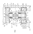
- FIGURE 5 is a fragmentary partially broken away sectional view illustrating the relationship of the carriage 300 to the guideways 900 and the relationship of the guideways to the wheel slide 400.
- the carriage 300 has a vertical back wall 304 which extends between the side walls 301 and 302.
- a relatively small front wall 306 projects from the side wall 302 toward the opposite side wall 301.
- the walls 301, 302, 304 and 306 of the carriage 300 cooperate to partially define the vertically extending chamber 307 disposed within the carriage 300 and enclosing the wheel slide 400 and the guideways 900.
- the chamber 307 has a rectangular cross sectional configuration throughout its length.
- the carriage walls 301, 302, 304 and 306 support the guideways 901, 902 and 903 to prevent deflection of the guideways during a grinding operation. Since the gudeways 900 are solidly supported by the carriage 300, relatively large operating forces can be transmitted from the wheel slide 400 to the rigid guideways 900 and carriage 300 without deflecting either the guideways or carriage.
- the guideways 901, 902 and 903 are securely mounted in the carriage chamber 307 by cast-in-situ bodies of material 904, 905 and 906 which are disposed between the guideways 901, 902 and 903 and as cast side surfaces inside the carriage 300.
- the bodies 904, 905 and 906 of cast-in-situ material could be formed of many different known materials, it is preferred to use "Sikadur 42" (Trademark) structural adhesive which is commercially available from Sika Corporation and is an epoxy resin with sand and/or quartz aggregate fillers.
- the cast-in-situ bodies of material 904, 905 and 906 enable the guideways 901, 902 and 903 to be connected with as cast surfaces of the chamber 307 without machining the surfaces.
- the cast-in-situ body of material 904 is disposed between a vertical, as cast, flat side surface 309 of the carriage side wall 301 and a flat vertically extending outer side surface 908 on the guideway 901.
- the outer side surface 908 of the guideway 901 extends generally parallel to the inner side surface 309 of the carriage 300, the guideway 901 is accurately positioned in a vertically extending orientation relative to the rough, as cast, surface 309 of the carriage.
- a slight misalignment between the outer side surface 908 f the guideway 901 and the rough inner side surface 309 of the carriage 300 is accommodated by the body 904 of cast-in-situ material.
- the body 904 of cast-in-situ material extends between a flat outer side surface 909 on the guideway 901 and a portion of a flat inwardly facing side surface 310 on the end wall 304 of the carriage 300.
- the body 904 of cast-in-situ material cooperates with the as cast carriage surfaces 309 and 310 and guideway surfaces 908 and 909 to accurately position the guideway 901 relatively to the carriage and to securely hold the guideway in place during operation of the grinding apparatus.
- the guideways 902 and 903 are accurately positioned and held in place in the carriage chamber 307 in a similar manner by the bodies 905 and 906 of cast-in-situ material.
- the guideway 902 has a flat vertical side surface 910 which faces forwardly toward a flat vertical inner side surface 311 of the carriage 301.
- the second outer side surface 912 on the guideway 902 faces outwardly toward a flat vertical inner side surface 312 on the inside of the carriage wall 302.
- the body 905 of cast-in-situ material extends between the as cast inner side surfaces 311 and 312 of the carriage 300 and the outer side surfaces 910 and 912 of the guideway 902 to accurately locate the guideway 902 relative to the carriage 300 and to firmly hold the guideway in position.
- the guideway 903 has flat vertical outer side surfaces 913 and 914 which extends parallel to and face toward the inner side surfaces 310 and 312 in the carriage 300.
- the body 906 of cast-in-situ material cooperates with the guideway 903 and the as cast surfaces 310 and 312 of the carriage 300 to accurately position the guideway relative to the carriage and to hold the guideway in position. Since the bodies 904, 905 and 906 of cast-in-situ material enable the guideways 901, 902 and 903 to be accurately positioned relative to the carriage without machining the inner side surfaces of the carriage, the cost of mounting the guideways is minimized.
- the guideway 901 has a pair of flat vertical guide surfaces 916 and 917 which are disposed in a common plane extending parallel to the vertical plane containing the axes A and B of rotation of the workpiece and grinding wheel.
- the guide surfaces 916 and 917 cooperate with hydrostatic bearings 406 and 407 on the main way block 401 to guide vertical movement of the way block.
- the guide ways 902 and 903 have flat vertical guide surfaces 918 and 919 which are disposed in a common vertical plane extending parallel to the guide surfaces 916 and 917.
- the guide surfaces 918 and 919 are disposed the same distance from a vertical plane containing the axis B of rotation of the grinding wheel as are the guide surfaces 916 and 917.
- the guide surfaces 918 and 919 cooperated with hydrostatic bearings 408 and 409 on the rectangular main section 401 of thw wheel slide 400 to further guide vertical movement of the wheel slide.
- the parallel guide surfaces 916, 917, 918 and 919 on the guideways 901, 902 and 903 cooperate with the hydrostatic bearings 406, 407, 408 and 409 to prevent sideways movement of the wheel slide 400 along the pivot axis G.
- the guideways 902 and 903 have parallel vertical guide surfaces 920 and 922 which cooperate with hydrostatic bearings 410 and 411 to hold the rectangular secondary section 402 of the wheel slide 400 against forward and backward movement along the horizontal axis H.
- the axis H is disposed in the same vertical plane as the axis A and B of rotation of the workpiece and grinding wheel.
- the secondary section 402 is of the wheel slide 400 is connected with the main section 401 by the pivot mounting assembly 403 and adjustment assembly 404 to hold the main section 401 of the wheel slide against movement along the horizontal axis H.
- the main section 401 of the wheel slide 400 holds the secondary section 402 against movement along the axis G.
- the mounting assembly 403 pivotally interconnects the main section 401 and secondary section 402 of the wheel slide.
- the mounting assembly 403 includes an axle shaft 412 which has an interface fit with an opening in the secondary section 402 of the wheel slide 400 and is held in place by a nut 413.
- a nut assembly 414 is fixedly connected with and forms part of the axle shaft 412 and meshingly engages the drive screw 62.
- the axle shaft 412 extends from the opposite side of the nut assembly 414.
- the main section 401 of the wheel slide 400 is pivotally mouted on the axle 412 by bearings 415 and 416.
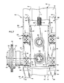
- FIGURE 6 illustrates the relationship between the carriage 300, the guideways 900, the wheel slide 400, the grinding wheel 500 and the adjustment assembly 404.
- the main section 401 of the wheel slide 400 is provided with a second or lower set of hydrostatic bearing 420, 421, 422 and 423 which cooperate with the guide surfaces 916, 917, 918 and 919 to further guide vertical movement of the wheel slide 400 relative to the guideways 901, 902 and 903.
- a second set of hydrostatic bearings 424 and 425 on the secondary section 402 of the wheel slide 400 cooperate with the guide surfaces 920 and 922 on the guideways 902 and 903 to guide vertical movement of the secondary section of the wheel slide.
- the bodies 904, 905 and 906 of cast-in-situ material extend throughout the length of the guideways 901, 902 and 903 to position and support the guidesways relative to the inner side surfaces 309, 310, 311 and 312 on the carriage 300.
- the angular position of the main section 401 of the wheel slide 400 is adjustable relative to the secondary section 402 upon operation of the adjustment assembly 404.
- the adjustment assembly 404 includes adjustment shaft 428 which is rotatably supported on the secondary wheel slide section 402 by bearings 430.
- An eccentric section 431 is formed as one piece with the rotatable shaft 428 and is engaged by a pair of arcuate follower sections 432 and 433.
- a piston 434 presses the retaining plate 436 against one of the follower sections 433 to clamp the eccentric 431 between the two follower sections 432 and 433.
- the follower sections 432 and 433 then hold the eccentric 431 and support shaft 428 against rotational movement relative to the wheel slide 400. This locks the main section 401 of the wheel slide in a predetermined orientation relative to the secondary section 402 of the wheel slide.
- the piston 434 is spring biased against the retainer plate 436.
- the spring biased piston 434 presses the retainer plate 436 against the followers 432 and 433 to lock the main and secondary sections 401 and 402 of the wheel slide against movement relative to each other.
- hydraulic fluid is conducted under pressure into an annular chamber 439. This urges the piston 434 toward the left (as viewed in FIGURE 6) against the influence of the biasing spring to release the eccentric for rotational movement so that the angular position of the main section 401 of the wheel slide can be adjusted relative to the secondary section 402 of the wheel slide.
- the amount of angular adjustment between the main and secondary sections 401 and 402 of the wheel slide is relatively small. This is because the drive screw 62 extends through the main section 401 of the wheel slide. Although the main section 401 of the wheel slide pivots about the axle 412 of FIGURE 5 upon operation of the adjustment assembly 404, this pivoting movement must be accommodated by the threads between the drive shaft 62 and the nut assembly 412.
- the grinding wheel assembly 500 of includes a stationary support axle or arbor 502 which is fixedly connected with the main section 401 of the wheel slide 400.
- the central axis of the support arbor 502 is coincident with the axis of rotation B of the grinding wheel 501 and is disposed midway between opposite vertical sides 441 and 442 of the main section 401 of the wheel slide 400.
- the grinding wheel assembly 500 includes a tubular base section 504 which is rotatably supported on cylindrical sections of the stationary arbor 502 by bearings 506 and 507.
- a circular outer section 508 is fixedly connected to a circular outer end of the base section 504 by suitably fasteners 509.
- the annular grinding wheel 501 is clamped between the base section 504 and an annular retaining ring 510.
- the retaining ring 510 has internal threads which engage external threads on the outer section 508 of the grinding wheel assembly.
- the base section 504 is provided with a circular sheave or pulley 512 which is engaged by the belt 804.
- the belt 804 rotates the base section 504, outer section 508, retainer ring 510 and grinding wheel 501 about the stationary arbor 502 during operation of the grinding wheel drive motor 801. Since the arbor 502 is stationary and is fixedly connected to the main section 401 of the wheel slide 400, the arbor 502 provides a solid mounting for the grinding wheel 501. In addition, the stationary arbor 502 reduces the rotating mass of the grinding wheel assembly 500 and thereby facilitates varying the speed of rotation of the grinding wheel 501.
- FIGURE 7 is a fragmentary side elevational view depicting the relationship of the wheel slide 400 to the ways 901, 902 and 903.
- the rectangular secondary section 402 of the wheel slide 400 is held against movement along the axis of rotation B of the grinding wheel 501 by engagement of the hydrostatic bearings 410, 411, 424 and 425 with the guide surfaces 920 and 922 of the guideways 902 and 903.
- Inner side surfaces 916 and 917 on the main guideway 901 and the inner side surfaces 918 and 919 (FIGURE 6) on the guideways 902 and 903 cooperate with the hydrostatic bearings, including the hydrostatic bearings 408, 409, 422 and 423, on the main section 401 of the wheel slide 400 to hold the wheel slide against sideways movement in a direction transverse to the axis of rotation B of the grinding wheel.
- the guideways 901, 902 and 903 provide a solid support for the wheel slide 400.
- the axis F of drive screw 62 extends parallel to the vertical longitudinal central axes of the guideways 901, 902 and 903. Therefore, rotation of the drive screw 62 results in the wheel slide 400 being moved vertically along the guideways without changing the orientation of the grinding wheel axis B relative to the guideways.
- a single secondary section 402 has been shown connected only with one side of the main section 401 of the wheel slide 400, it is contemplated that a second secondary section, having the same general configuration as the section 402, could be connected to the opposite side of the main section 401 of the wheel slide.
- a pivot connection corresponding to the pivot connection 403 and an adjustment assembly, corresponding to the adjustment assembly 404, would be provided in association with the secondary wheel slide section on the opposite side of the main wheel slide section 401 from the wheel slide section 402.
- the double way 901 would be formed to two ways, similar to the ways 902 and 903.
- FIGURE 8 is an exaggerated illustration of the manner in which the axis of rotation B of the grinding wheel 501 is skewed relative to the horizontal axis A of rotation of the workpiece by operation of the adjustment assembly 404.
- operation of the adjustment assembly 404 pivots the main section 401 of the wheel slide 400 about the mounting assembly 403.
- the axis B of rotation of the grinding wheel 501 moves from the horizontal orientation shown in FIGURE 7 to the skewed orientation shown in FIGURE 8. This results in circular outer side surfaces 514 of the grinding wheel 501 being skewed at an acute angle, indicated at K in FIGURE 8, relative to the horizontal axis A of rotation of the workpiece.
- the main section 401 will be rotated through a relatively small distance relative to the secondary section 402 and the angle K will be smaller than is indicated in FIGURE 8 for most grinding operations. In fact, it is contemplated that for the majority of grinding operations the axis B of rotation of the grinding wheel 501 will be horizontal.
- the hydrostatic bearings 406, 407, 408 and 409 (FIGURE 5) and the hydrostatic bearings 420, 421, 422 and 423 (FIGURE 6) allow the main section 401 to slide on a film of lubricating liquid between the bearings and the guide surfaces 416, 417, 418 and 419. This enables the main section 401 of the wheel slide 400 to be pivoted relative to the secondary section 402 by operation of the adjustment assembly 404 without excessively wearing the guide surfaces.
- FIGURE 9 illustrates the relationship of a hydrostatic bearing 411 on the secondary guide section 402 relative to guide surface 922 on a guide way 903.
- the hydrostatic bearing 411 includes a rectangular base or shoe 450 having openings 451 which are connected in fluid communication with passages 452 formed in the secondary section 402 of the wheel slide 400.
- High pressure lubricating fluid that is oil, flows from the passage 452 between the rectangular base section 450 and the guide surface 922 in the manner indicated by the arrow M in FIGURE 9. Load forces are transmitted through the film 450 in a known manner.
- FIGURE 10 illustrates a guard assembly 1000 which is connected with the carriage 300.
- the guard assembly 1000 includes a relatively heavy metal shield or plate 1001 which is movable vertically along a pair of parallel guide tracks 1002 and 1003 by a piston cylinder type motor 1004.
- a pair of latches 1005 and 1006 are automatically actuated to retain the shield in place.
- pneumatic motors 1007 and 1008 actuate the latches 105 and 106 to release the shield 1001.
- the motor 1004 then raises the shield to a position above the grinding wheel 501 to provide access to the grinding wheel assembly 500.
- the guard or shield 1001 When the guard or shield 1001 is lowered, it blocks the path of any fragments which may tend to fly axially outwardly from the grinding wheel assembly 500 in the event of breakage of the grinding wheel 501.
- the peripheral sides of the grinding wheel 501 are enclosed by the side section 306 of the carriage 300 and the guide track 1002.
- the end wall 304 (FIGURE 6) blocks possible fragments from flying axially rearwardly from the grinding wheel assembly 500.
- the cross section 303 of the carriage 300 blocks the upward path of movement of grinding wheel fragments.
- the guide assembly 1000 is mounted on the carriage 300. Therefore, the weight of the guard assembly does not contribute to the overall weight of the wheel slide 400. Rapid and accurate positioning of the grinding wheel 501 is promoted by having the wheel slide 400 as light as possible.
- the carriage drive assembly 70 is operated to move the carriage 300 to a withdrawn position illustrated in dashed lines in FIGURE 1.
- the carriage 300 When the carriage 300 is in this position it encloses the rightward end portion (as viewed in FIGURE 1) of the footstock 23. This results in the space between the foot stock 23 and the headstock 21 being open.
- the workpiece W is then mounted on the footstock 23 and headstock 21. Since the carriage 300 is withdrawn and the space between the headstock 21 and footstock 23 is open, a workpiece W can be easily mounted on the headstock 21 and footstock 23 with known workpiece loading mechanisms.
- the carriage drive assembly 70 is then operated to move carriage 300 along the horizontal guide tracks 11 and 12 until the grinding wheel 501 is in vertical alignment with a portion of the workpiece to be ground.
- the wheel slide drive assembly 60 is then operated to lower the wheel slide 400.
- the motor 61 rotates the drive screw 62 to move the wheel slide and grinding wheel 501 verticaly downwardly. Since the wheel slide 400 is relatively light, the wheel slide drive motor 61 can be operated at a relatively high speed to quickly and accurately position the grinding wheel 501 relative to the workpiece.
- the wheel slide drive motor 61 When the selected area on the workpiece has been ground, the wheel slide drive motor 61 is operated to cause the drive screw 62 to raise the wheel slide 400 upwardly away from the workpiece. As the occurs, the distance between the axis of rotation B of the grinding wheel 501 and the output shaft 803 of the grinding wheel drive motor 801 decreases. As this occurs, the biasing assembly 808 pivots the base plate 805 in a clockwise direction about the pivot support 806 to maintain desired tension in the drive belt 804. Once the grinding wheel 501 has been raised clear of the workpiece, the carriage drive assembly 70 is operated to move the grinding wheel into vertical alignment with the next succeeding area to be ground on the workpiece W.
- the adjustment assembly 404 is operated to pivot the main section 401 of the wheel slide 400 relative to the secondary section 402 about the pivot mounting assembly 403 (FIGURE 5).
- the adjustment assembly 404 is operated to pivot the main section 401 of the wheel slide 400 relative to the secondary section 402 about the pivot mounting assembly 403 (FIGURE 5).
- the shaft 428 which is integrally formed with the eccentric 431, is then rotated to pivot the main section 401 of the wheel slide 400 relative to the secondary section 402 about the axis G of the pivot mounting assembly 403.
- the axis B of rotation of the grinding wheel moves into a skewed relationship with a horizontal plane, in a manner similar to that illustrated in FIGURE 8.
- the fluid pressure on the piston 434 (FIGURE 6) is released and biasing springs again cause the locking elements 432 and 433 to firmly grip the eccentric 431 to prevent relative movement between the main section 401 and secondary section 402 of the wheel slide 400.
Landscapes
- Engineering & Computer Science (AREA)
- Mechanical Engineering (AREA)
- Grinding Of Cylindrical And Plane Surfaces (AREA)
- Machine Tool Units (AREA)
Applications Claiming Priority (2)
| Application Number | Priority Date | Filing Date | Title |
|---|---|---|---|
| US925367 | 1986-10-30 | ||
| US06/925,367 US4754574A (en) | 1986-10-30 | 1986-10-30 | Apparatus for grinding a workpiece |
Publications (2)
| Publication Number | Publication Date |
|---|---|
| EP0265953A2 true EP0265953A2 (de) | 1988-05-04 |
| EP0265953A3 EP0265953A3 (de) | 1989-05-17 |
Family
ID=25451636
Family Applications (1)
| Application Number | Title | Priority Date | Filing Date |
|---|---|---|---|
| EP87115922A Withdrawn EP0265953A3 (de) | 1986-10-30 | 1987-10-29 | Schleifmaschine |
Country Status (4)
| Country | Link |
|---|---|
| US (1) | US4754574A (de) |
| EP (1) | EP0265953A3 (de) |
| JP (1) | JPS63127859A (de) |
| CA (1) | CA1279194C (de) |
Cited By (1)
| Publication number | Priority date | Publication date | Assignee | Title |
|---|---|---|---|---|
| EP0413515A1 (de) * | 1989-08-17 | 1991-02-20 | Silicon Technology Corporation | Gerüst für die Lagerung der Spindel einer Innenlochsäge |
Families Citing this family (3)
| Publication number | Priority date | Publication date | Assignee | Title |
|---|---|---|---|---|
| DE19921785B4 (de) * | 1999-05-11 | 2005-11-24 | Erwin Junker Maschinenfabrik Gmbh | Verfahren zum Schleifen von konvexen Laufflächen und Außendurchmessern an Wellen mit wenigstens einem scheibenförmigen Wellenabschnitt sowie Schleifmaschine zur Durchführung des Verfahrens |
| EP1486289A3 (de) * | 2003-06-12 | 2005-03-09 | Koyo Seiko Co., Ltd. | Verfahren zum Schleifen der Wälzlagereinheit eines Rades |
| TWI388397B (zh) * | 2004-02-25 | 2013-03-11 | Studer Ag Fritz | 用於工作件加工的加工機 |
Family Cites Families (25)
| Publication number | Priority date | Publication date | Assignee | Title |
|---|---|---|---|---|
| US1862379A (en) * | 1928-03-19 | 1932-06-07 | Herman F Koestlin | Grinding machine |
| US1945396A (en) * | 1929-04-19 | 1934-01-30 | Gen Electric | Grinding machine |
| US1946864A (en) * | 1930-03-17 | 1934-02-13 | Jr Orville H Foster | Grinding machine |
| US2088402A (en) * | 1935-08-16 | 1937-07-27 | Eastwood Nealley Corp | Resurfacing machine for paper making machine suction boxes |
| US2076179A (en) * | 1936-06-10 | 1937-04-06 | Brown & Sharpe Mfg | Machine tool |
| US2118304A (en) * | 1936-10-03 | 1938-05-24 | Franz Fuchs | Grinding machine |
| US2128023A (en) * | 1937-03-08 | 1938-08-23 | Eastwood Nealley Corp | Suction box conditioner |
| US2336145A (en) * | 1942-03-30 | 1943-12-07 | Michael Cisar | Method for finishing metal parts |
| US2441045A (en) * | 1945-08-09 | 1948-05-04 | Edward J Toepfer | Lawn mower sharpener |
| US2471561A (en) * | 1945-10-25 | 1949-05-31 | Fielding Edgar Charles | Guard for grinding machines and the like |
| US2589191A (en) * | 1947-11-10 | 1952-03-11 | Timken Roller Bearing Co | Groove dressing tool |
| US2710494A (en) * | 1951-08-04 | 1955-06-14 | Norton Co | Grinding machine |
| US2774191A (en) * | 1954-08-10 | 1956-12-18 | Bouchez Jean Henri Mari Joseph | Cutting machine |
| US2981035A (en) * | 1958-11-24 | 1961-04-25 | Nat Broach & Mach | Grinder |
| FR1303116A (fr) * | 1961-07-27 | 1962-09-07 | Dispositif de rectification circulaire adaptable sur machines de rectification planétaire | |
| US3247621A (en) * | 1963-12-05 | 1966-04-26 | Sheffield Corp | Machine assembly |
| US3616578A (en) * | 1969-01-10 | 1971-11-02 | Ingersoll Milling Machine Co | Method for turning workpieces |
| US4164828A (en) * | 1975-06-26 | 1979-08-21 | Hiroshi Ishizuka | Abrasive machine for stones |
| FR2425918A2 (fr) * | 1978-01-31 | 1979-12-14 | Mavilor Manuf Vilebrequins | Cadre vertical mobile support de tete d'entrainement d'outils avec moyen de guidage par rapport au bati, pour toutes machines-outils d'utilisation generale |
| FR2416083A1 (fr) * | 1978-01-31 | 1979-08-31 | Mavilor Sa | Cadre vertical mobile support de tete d'entrainement d'outils avec moyen de guidage par rapport au bati, pour toutes machines-outils d'utilisation generale |
| DE3005606C2 (de) * | 1980-02-15 | 1992-08-27 | Hauni-Werke Körber & Co KG, 2050 Hamburg | Numerisch gesteuerte Maschine zum Schleifen mehrerer unterschiedlicher Flächen an ein- und demselben Werkstück |
| US4539876A (en) * | 1983-10-11 | 1985-09-10 | The Warner & Swasey Company | Machine tool |
| JPS60228063A (ja) * | 1984-04-20 | 1985-11-13 | Matsushita Electric Ind Co Ltd | 曲面創成研磨装置 |
| PL147217B1 (en) * | 1985-02-08 | 1989-05-31 | Ct Badawczo Konst Obrabiarek | Machine tool |
| JPS624540A (ja) * | 1985-07-02 | 1987-01-10 | Citizen Watch Co Ltd | テ−ブル機構 |
-
1986
- 1986-10-30 US US06/925,367 patent/US4754574A/en not_active Expired - Fee Related
-
1987
- 1987-10-15 CA CA000549411A patent/CA1279194C/en not_active Expired - Lifetime
- 1987-10-29 EP EP87115922A patent/EP0265953A3/de not_active Withdrawn
- 1987-10-30 JP JP62275573A patent/JPS63127859A/ja active Pending
Cited By (1)
| Publication number | Priority date | Publication date | Assignee | Title |
|---|---|---|---|---|
| EP0413515A1 (de) * | 1989-08-17 | 1991-02-20 | Silicon Technology Corporation | Gerüst für die Lagerung der Spindel einer Innenlochsäge |
Also Published As
| Publication number | Publication date |
|---|---|
| EP0265953A3 (de) | 1989-05-17 |
| CA1279194C (en) | 1991-01-22 |
| US4754574A (en) | 1988-07-05 |
| JPS63127859A (ja) | 1988-05-31 |
Similar Documents
| Publication | Publication Date | Title |
|---|---|---|
| USRE33732E (en) | Method of machining a workpiece in a turret lathe and an NC lathe for performing this method | |
| JP3090857B2 (ja) | 段付き工作物外周加工機 | |
| EP1201353B1 (de) | Drehtischvorrichtung | |
| US5667432A (en) | Grinding machine | |
| CA1176438A (en) | Machine tools | |
| US3703847A (en) | Support device for machining workpieces | |
| US4538945A (en) | Apparatus for machining a polygon profile on a workpiece | |
| US4642861A (en) | Machine tool construction | |
| US4653233A (en) | Machine for grinding of toric surfaces on optic lenses | |
| US3800621A (en) | Cam control grinding machine | |
| US4754574A (en) | Apparatus for grinding a workpiece | |
| US4621405A (en) | Drive mechanism for the main spindle of a rotating tool turret machine | |
| US4539876A (en) | Machine tool | |
| US4624159A (en) | Lathe accessory | |
| CA1084270A (en) | Orbiting cutter tangential machining tool | |
| KR100563950B1 (ko) | 복합가공테이블 및 이 테이블을 구비한 수직선반 | |
| EP0235311B1 (de) | Werkzeugmaschine | |
| US4615652A (en) | Cutting tool compensator for rotary machine tool | |
| USRE34155E (en) | Machining a workpiece in a turret lathe and an NC lathe therefor | |
| US4096667A (en) | Internal grinding machine | |
| US4939963A (en) | Fixture for precision turning of a lateral surface | |
| US6824142B2 (en) | Method of alignably supporting a work piece for rotary movements | |
| US6869083B2 (en) | Eccentric work piece holder and method of making same | |
| US5388934A (en) | Machine tools | |
| GB2085771A (en) | Precision grinder |
Legal Events
| Date | Code | Title | Description |
|---|---|---|---|
| PUAI | Public reference made under article 153(3) epc to a published international application that has entered the european phase |
Free format text: ORIGINAL CODE: 0009012 |
|
| AK | Designated contracting states |
Kind code of ref document: A2 Designated state(s): AT BE CH DE ES FR GB GR IT LI LU NL SE |
|
| RBV | Designated contracting states (corrected) |
Designated state(s): DE FR GB IT |
|
| RAP1 | Party data changed (applicant data changed or rights of an application transferred) |
Owner name: THE PRATT & WHITNEY COMPANY, INC. |
|
| PUAL | Search report despatched |
Free format text: ORIGINAL CODE: 0009013 |
|
| AK | Designated contracting states |
Kind code of ref document: A3 Designated state(s): DE FR GB IT |
|
| STAA | Information on the status of an ep patent application or granted ep patent |
Free format text: STATUS: THE APPLICATION IS DEEMED TO BE WITHDRAWN |
|
| 18D | Application deemed to be withdrawn |
Effective date: 19891118 |
|
| RIN1 | Information on inventor provided before grant (corrected) |
Inventor name: CLOUGH, ARTHUR H. Inventor name: KNIGHT, EDWIN L. |