EP0265975B2 - Modular rolling stand - Google Patents
Modular rolling stand Download PDFInfo
- Publication number
- EP0265975B2 EP0265975B2 EP87201727A EP87201727A EP0265975B2 EP 0265975 B2 EP0265975 B2 EP 0265975B2 EP 87201727 A EP87201727 A EP 87201727A EP 87201727 A EP87201727 A EP 87201727A EP 0265975 B2 EP0265975 B2 EP 0265975B2
- Authority
- EP
- European Patent Office
- Prior art keywords
- rolling stand
- stand
- rolls
- rolling
- base
- Prior art date
- Legal status (The legal status is an assumption and is not a legal conclusion. Google has not performed a legal analysis and makes no representation as to the accuracy of the status listed.)
- Expired - Lifetime
Links
- 238000005096 rolling process Methods 0.000 title claims abstract description 33
- 239000002893 slag Substances 0.000 claims abstract description 9
- 238000001816 cooling Methods 0.000 claims abstract description 3
- 238000011144 upstream manufacturing Methods 0.000 claims description 6
- 239000007921 spray Substances 0.000 claims description 2
- 238000007599 discharging Methods 0.000 claims 1
- XLYOFNOQVPJJNP-UHFFFAOYSA-N water Substances O XLYOFNOQVPJJNP-UHFFFAOYSA-N 0.000 description 5
- 238000009434 installation Methods 0.000 description 4
- 239000000498 cooling water Substances 0.000 description 2
- 230000001419 dependent effect Effects 0.000 description 1
- 239000003517 fume Substances 0.000 description 1
- 239000004519 grease Substances 0.000 description 1
- 239000011261 inert gas Substances 0.000 description 1
- 239000010687 lubricating oil Substances 0.000 description 1
- 238000003801 milling Methods 0.000 description 1
- 239000003921 oil Substances 0.000 description 1
- 238000002360 preparation method Methods 0.000 description 1
- 239000002699 waste material Substances 0.000 description 1
Images

Classifications
-
- B—PERFORMING OPERATIONS; TRANSPORTING
- B21—MECHANICAL METAL-WORKING WITHOUT ESSENTIALLY REMOVING MATERIAL; PUNCHING METAL
- B21B—ROLLING OF METAL
- B21B13/00—Metal-rolling stands, i.e. an assembly composed of a stand frame, rolls, and accessories
-
- B—PERFORMING OPERATIONS; TRANSPORTING
- B21—MECHANICAL METAL-WORKING WITHOUT ESSENTIALLY REMOVING MATERIAL; PUNCHING METAL
- B21B—ROLLING OF METAL
- B21B31/00—Rolling stand structures; Mounting, adjusting, or interchanging rolls, roll mountings, or stand frames
- B21B31/02—Rolling stand frames or housings; Roll mountings ; Roll chocks
- B21B31/06—Fastening stands or frames to foundation, e.g. to the sole plate
Definitions
- This invention concerns a complete modular rolling stand.
- the invention concerns a rolling stand already pre-arranged in the manufacturer's factory for installation and immediate functioning without the normal operations of assembly, setting up, testing, etc.
- Rolling stands may have their rolls supported at both ends or supported as a cantilever and the axes of the rolls may be horizontal, vertical or inclined.
- the rolling stands having their rolls supported at both ends may be of any type such as stands with housings, cartridge-type stands, pre-stressed stands, etc.
- the present invention therefore means by the words "rolling stand” any type of rolling stand which comprises rolls supported at both ends or supported as a cantilever.
- the known art provides for rolling stands, even those having rolls supported as a cantilever, to cooperate on a base which comprises civil works such as conduits, discharge channels, hydraulic works prepared for individual tasks, etc., the whole having the purpose of supplying the rolling stand itself.
- Document EP-A-0 057 101 discloses a rolling stand which is mounted on a frame, said frame being fixed to a base which includes a baseplate and is detachably secured to foundation skids. Said base is not provided with any means for supporting the motor for driving the rolls, or for supporting a control panel. The stand is also not provided with feeder and service conduits located in predetermined areas of the base.
- the problem underlying the invention resides in how to facilitate the installation of a rolling mill and to shorten the time necessary for replacement of a roll milling stand.
- the rolling stand leaving its manufacturer has already been tested and perfected in every detail and component, so that for its installation it is enough to fix its base to the ground and to connect the stand to its supply means as already arranged; the machine has already been tested and is operational at the time when the final connection is made.
- the stand according to the invention entails also the advantage that it possesses standard dimensions and can therefore be readily combined with other stands or other machines without creating problems of disturbance of the layout or foundations, such problems not being easy to foresee in the case of traditional machines.
- the rolling stand comprises a soundproofed room which holds the motor.
- Such room is equipped with means to cool the environment and contains the electrical control and operating panel.
- the stand includes a base containing zones individually equipped for the positioning and passage of the various feed and service units, whether these be for the water, hydraulic or electrical supplies, etc.
- the various supply and service units are equipped at their ends with means to obtain a speedy and firm connection to the stand or to the preceding or subsequent usage means.
- a motor and the stand itself are positioned on the base, while a channel to discharge slag is included in direct cooperation with the stand.
- the stand in itself may be provided with shields, and means to actuate the shields and other equipment.
- the machine is completely finished in every detail in the supplying factory, where it may be fitted with means to cool the rolls, connections required for the means to cool the motor, brackets for hydraulic clamping and every other necessary component.
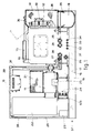
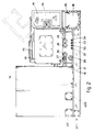
- a stand 10 connected to a motor 11 is located on a base 37, which in this example comprises levelling feet 16 solidly fixed to a base plate 17.
- the base 37 may include plates for lateral connection to other modular units.
- the leveling feet 16 are positioned crosswise to the lengthwise vertical plane of the machine.
- a soundproofed room 19 cooperates with the motor 11 and comprises a door 20 for access to the room and also at least one window 38.
- An airconditioner unit 39 or at least a means to cool the environment is located in the room 19 to keep the inside of the room at the required temperature.
- Means to detect fumes or fire and possible extinguishers may also be provided.
- An electrical control panel 22 is comprised inside the soundproofed room 19 and will be complete with all the actuation means and controls required for the proper and complete functioning of the rolling stand, equipment and every other connected element.
- the electrical control panel 22 is connected to the motor 11 through a connection box 25 and is fed from the exterior supply through a feed box 23.
- the feed box 23 comprises means for speedy connection to the supply sources or other external utilities and to other units positioned alongside the stand.
- a series of electrical conduits 24 passes transversely through the base of the stand and provides the electrical connections to make possible the passage and supply of power, services and controls.
- the electrical conduits 24 are already connected to the feed box 23 and thereby to the electrical control panel 22 and utilities.
- Connection to the exterior takes place normally by a butt connection through the feed box 223 but may also take place through the feed box 23.
- suitable means are included for connection to analogous conduits included in stands located upstream and downstream, or to supply, service and control means located upstream, or to other usage means located downstream.
- the electrical conduits 24 serve to convey motive power, generally electrical power, and also the electrical controls and links.
- a means 21 to cool the motor 11 is also comprised in the soundproofed room 19 and is connected directly to a cooling water inflow pipe 27 and to a water return flow pipe 30.
- the cooling water inflow pipe 27 supplies water at the required pressure, whereas the return flow pipe 30 acts as a drain for water used either within the cooler means 21 or in the airconditioner 39 or in other possible usage means.
- the rolling stand 10 of Figs.1 and 2 is equipped with rolls 12 supported as a cantilever, which in this case have a horizontal rolling axis 13 and comprise already installed brackets for hydraulic clamping and balancing as required to withstand and annul the weights acting on the shafts of the rolls 12.
- the rolling stand 110 of Fig.3 is provided with rolls 112 supported at both their ends and with rolling shafts 113 and is already directly equipped with the necessary equipment and usage devices.
- Cooling units 36-136 which are fed with water under pressure by a pipe 29 are included in cooperation with rolls supported as cantilevers 12 or supported at both ends 112.
- Such pipe 29 feeds also spray nozzles 35 which scour and clean a slag discharge channel 18.
- Such discharge channel 18 for slag is comprised in the base of the stand and runs crosswise to the stand, being positioned in cooperation with rolls 12 supported as a cantilever or with rolls 112 supported at both ends.
- the rolls 12 supported as a cantilever and possibly at least part of the rolls 112 supported at both ends are protected by a shield 14-114 which can be lifted by a jack 15 to permit ready access.
- a shield 214 In the case of a stand 110 having rolls 112 supported at both ends the zone of roll extensions 40 and possibly also a gear box 41 may be protected by a shield 214.
- One or more reserved conduits 28 may be provided in the base 37, which will also include one or more conduits for lubricating oil 26, conduits for grease 31, conduits for oil under pressure 32, conduits for oleodynamic drive units 33 and possible reserve conduits 34.
- conduits may be provided for other functions such as compressed air, an inert gas, etc.
- All such conduits positioned crosswise to the base 37 include suitable terminal connections able to connect them to coordinated supply conduits positioned upstream or to further usage means or to conduits located downstream of the stand itself.
- the channel for discharge of slag 18 too comprises suitable means for connection to analogous channels or coordinated discharge means located upstream or downstream of such discharge channel 18.
- Each zone of the stand is therefore prepared for individual tasks and finalized functions and includes the operational means and necessary auxiliary means as well as possible means for connections upstream and downstream.
- the stand 110 of Fig.3 comprises also the gear box 41 and extensions 40.
- the stand according to the invention is therefore perfectly finished and tested as regards all its parts when despatched from the manufacturer's factory, and this situation provides both its producer and the end-user with a great number of advantages and great usefulness.
- a first advantage lies in the fact that all the civil works forming part of the machine are already positioned and set up in the machine without any need to be arranged.
- a further advantage is the fact that all the parts of the stand are finished and ready, thus reducing sharply the times involved and the problems of despatch, storage, assembly and timing of start-up of the machine itself.
Landscapes
- Engineering & Computer Science (AREA)
- Mechanical Engineering (AREA)
- Metal Rolling (AREA)
- Electromagnets (AREA)
- Golf Clubs (AREA)
- Signal Processing For Digital Recording And Reproducing (AREA)
- Furnace Housings, Linings, Walls, And Ceilings (AREA)
- Furnace Details (AREA)
- Control Of Metal Rolling (AREA)
- Laminated Bodies (AREA)
Priority Applications (1)
| Application Number | Priority Date | Filing Date | Title |
|---|---|---|---|
| AT87201727T ATE73020T1 (de) | 1986-10-06 | 1987-09-10 | Modulaeres walzgeruest. |
Applications Claiming Priority (2)
| Application Number | Priority Date | Filing Date | Title |
|---|---|---|---|
| IT6048386U | 1986-10-06 | ||
| IT8660483U IT210790Z2 (it) | 1986-10-06 | 1986-10-06 | Gabbia di laminazione a modulo. |
Publications (3)
| Publication Number | Publication Date |
|---|---|
| EP0265975A1 EP0265975A1 (en) | 1988-05-04 |
| EP0265975B1 EP0265975B1 (en) | 1992-03-04 |
| EP0265975B2 true EP0265975B2 (en) | 1996-09-04 |
Family
ID=11291291
Family Applications (1)
| Application Number | Title | Priority Date | Filing Date |
|---|---|---|---|
| EP87201727A Expired - Lifetime EP0265975B2 (en) | 1986-10-06 | 1987-09-10 | Modular rolling stand |
Country Status (5)
| Country | Link |
|---|---|
| EP (1) | EP0265975B2 (it) |
| AT (1) | ATE73020T1 (it) |
| DE (1) | DE3777075D1 (it) |
| ES (1) | ES2030050T5 (it) |
| IT (1) | IT210790Z2 (it) |
Families Citing this family (2)
| Publication number | Priority date | Publication date | Assignee | Title |
|---|---|---|---|---|
| CN105537270A (zh) * | 2015-12-19 | 2016-05-04 | 重庆麦拓科技有限公司 | 一种轧机 |
| EP3883701B1 (en) * | 2018-11-23 | 2022-10-19 | John Cockerill S.A. | Flexible cold rolling mill and method for converting the same |
Family Cites Families (6)
| Publication number | Priority date | Publication date | Assignee | Title |
|---|---|---|---|---|
| DE545395C (de) * | 1927-04-08 | 1932-08-08 | Heraeus Vacuumschmelze A G | Kontinuierliche Walzenstrasse |
| US2722392A (en) * | 1949-04-02 | 1955-11-01 | United Eng Foundry Co | Connecting elements for a base and platform |
| GB1049763A (en) * | 1963-05-16 | 1966-11-30 | Davy & United Eng Co Ltd | Rolling mills |
| FR2044472A5 (en) * | 1969-05-22 | 1971-02-19 | Loire Atel Forges | Rolling mill stand for either horizontal - or vertical posn |
| DE2831699A1 (de) * | 1978-07-19 | 1980-01-31 | Fuhr Karl Maschf | Kaltwalzwerk fuer draht-, flach- und sonderprofile |
| SE432070B (sv) * | 1979-10-23 | 1984-03-19 | Strandell Per Olof | Anordning vid valsverk for valsning av stang och/eller trad |
-
1986
- 1986-10-06 IT IT8660483U patent/IT210790Z2/it active
-
1987
- 1987-09-10 EP EP87201727A patent/EP0265975B2/en not_active Expired - Lifetime
- 1987-09-10 DE DE8787201727T patent/DE3777075D1/de not_active Expired - Fee Related
- 1987-09-10 AT AT87201727T patent/ATE73020T1/de not_active IP Right Cessation
- 1987-09-10 ES ES87201727T patent/ES2030050T5/es not_active Expired - Lifetime
Also Published As
| Publication number | Publication date |
|---|---|
| ES2030050T5 (es) | 1997-01-01 |
| ES2030050T3 (es) | 1992-10-16 |
| DE3777075D1 (de) | 1992-04-09 |
| EP0265975A1 (en) | 1988-05-04 |
| ATE73020T1 (de) | 1992-03-15 |
| EP0265975B1 (en) | 1992-03-04 |
| IT210790Z2 (it) | 1989-01-11 |
| IT8660483V0 (it) | 1986-10-06 |
Similar Documents
| Publication | Publication Date | Title |
|---|---|---|
| US7143585B2 (en) | Turbine power plant, installation process and removal process of the turbine power plant | |
| US4944175A (en) | Universal rolling mill stand with adjustable sets of horizontal rolls and vertical rolls | |
| EP0265975B2 (en) | Modular rolling stand | |
| US8051693B2 (en) | Device for mounting and functional verification of roll fittings in rolling mill stands or rolling mill trains such as, e.g., tandem rolling mill trains | |
| ZA200406534B (en) | Method and device for changing pairs of working rolls and/or pairs of back-up rolls on roll stands. | |
| US6041637A (en) | Roll replacing method and system for chockless rolling mill | |
| JP4671505B2 (ja) | ロールスタンドの特に液状稼動媒体用の供給管,排出管及び分岐管の設備 | |
| JPS5995946A (ja) | ロ−ラ式ボウルミル | |
| US6732618B1 (en) | Machine tool | |
| JP4468492B2 (ja) | タンデムロールスタンド群を備えている圧延ライン | |
| CN101149153A (zh) | 紧凑的喷水器 | |
| EP0028424A1 (de) | Kombiniertes Kamm- und Traglager für Turbogeneratoren | |
| US4962657A (en) | Rolling mill train, particularly rolling mill train in a section mill | |
| US7104101B1 (en) | Roll stand | |
| US4907437A (en) | Universal rolling stand with rolling rings supported as cantilevers | |
| US5100068A (en) | Roller mill | |
| MXPA97000189A (en) | Lamination block compa | |
| EP0780168B1 (en) | Compact rolling block | |
| EP2131976B1 (en) | Bearing structure for continuous casting machine | |
| CN101878081A (zh) | 驱动装置 | |
| CN212057721U (zh) | 一种中央空调内机贴合式安装装置 | |
| JPS5816709A (ja) | 圧延設備 | |
| JP2683615B2 (ja) | 高炉の仕込装置用支持機枠 | |
| JP3302546B2 (ja) | 高炉用鉱石受金物の取り替え方法 | |
| JPS646962Y2 (it) |
Legal Events
| Date | Code | Title | Description |
|---|---|---|---|
| PUAI | Public reference made under article 153(3) epc to a published international application that has entered the european phase |
Free format text: ORIGINAL CODE: 0009012 |
|
| AK | Designated contracting states |
Kind code of ref document: A1 Designated state(s): AT BE CH DE ES FR GB GR IT LI LU NL SE |
|
| 17P | Request for examination filed |
Effective date: 19881026 |
|
| 17Q | First examination report despatched |
Effective date: 19900620 |
|
| GRAA | (expected) grant |
Free format text: ORIGINAL CODE: 0009210 |
|
| ITF | It: translation for a ep patent filed | ||
| AK | Designated contracting states |
Kind code of ref document: B1 Designated state(s): AT BE CH DE ES FR GB GR IT LI LU NL SE |
|
| PG25 | Lapsed in a contracting state [announced via postgrant information from national office to epo] |
Ref country code: SE Effective date: 19920304 Ref country code: NL Effective date: 19920304 Ref country code: LI Effective date: 19920304 Ref country code: GR Free format text: LAPSE BECAUSE OF FAILURE TO SUBMIT A TRANSLATION OF THE DESCRIPTION OR TO PAY THE FEE WITHIN THE PRESCRIBED TIME-LIMIT Effective date: 19920304 Ref country code: CH Effective date: 19920304 |
|
| REF | Corresponds to: |
Ref document number: 73020 Country of ref document: AT Date of ref document: 19920315 Kind code of ref document: T |
|
| REF | Corresponds to: |
Ref document number: 3777075 Country of ref document: DE Date of ref document: 19920409 |
|
| ET | Fr: translation filed | ||
| REG | Reference to a national code |
Ref country code: CH Ref legal event code: PL |
|
| NLV1 | Nl: lapsed or annulled due to failure to fulfill the requirements of art. 29p and 29m of the patents act | ||
| PG25 | Lapsed in a contracting state [announced via postgrant information from national office to epo] |
Ref country code: LU Free format text: LAPSE BECAUSE OF NON-PAYMENT OF DUE FEES Effective date: 19920930 |
|
| REG | Reference to a national code |
Ref country code: ES Ref legal event code: FG2A Ref document number: 2030050 Country of ref document: ES Kind code of ref document: T5 |
|
| PLBI | Opposition filed |
Free format text: ORIGINAL CODE: 0009260 |
|
| 26 | Opposition filed |
Opponent name: SMS SCHLOEMANN-SIEMAG AG Effective date: 19921203 |
|
| APAC | Appeal dossier modified |
Free format text: ORIGINAL CODE: EPIDOS NOAPO |
|
| PLAW | Interlocutory decision in opposition |
Free format text: ORIGINAL CODE: EPIDOS IDOP |
|
| ITF | It: translation for a ep patent filed | ||
| PUAH | Patent maintained in amended form |
Free format text: ORIGINAL CODE: 0009272 |
|
| STAA | Information on the status of an ep patent application or granted ep patent |
Free format text: STATUS: PATENT MAINTAINED AS AMENDED |
|
| PGFP | Annual fee paid to national office [announced via postgrant information from national office to epo] |
Ref country code: GB Payment date: 19960830 Year of fee payment: 10 |
|
| 27A | Patent maintained in amended form |
Effective date: 19960904 |
|
| AK | Designated contracting states |
Kind code of ref document: B2 Designated state(s): AT BE CH DE ES FR GB GR IT LI LU NL SE |
|
| PGFP | Annual fee paid to national office [announced via postgrant information from national office to epo] |
Ref country code: FR Payment date: 19960904 Year of fee payment: 10 |
|
| PGFP | Annual fee paid to national office [announced via postgrant information from national office to epo] |
Ref country code: ES Payment date: 19960917 Year of fee payment: 10 |
|
| PGFP | Annual fee paid to national office [announced via postgrant information from national office to epo] |
Ref country code: DE Payment date: 19960927 Year of fee payment: 10 |
|
| PGFP | Annual fee paid to national office [announced via postgrant information from national office to epo] |
Ref country code: BE Payment date: 19960930 Year of fee payment: 10 Ref country code: AT Payment date: 19960930 Year of fee payment: 10 |
|
| REG | Reference to a national code |
Ref country code: CH Ref legal event code: AEN Free format text: MAINTIEN DU BREVET DONT L'ETENDUE A ETE MODIFIEE |
|
| ET3 | Fr: translation filed ** decision concerning opposition | ||
| REG | Reference to a national code |
Ref country code: ES Ref legal event code: DC2A Kind code of ref document: T5 Effective date: 19961129 |
|
| PG25 | Lapsed in a contracting state [announced via postgrant information from national office to epo] |
Ref country code: GB Free format text: LAPSE BECAUSE OF NON-PAYMENT OF DUE FEES Effective date: 19970910 Ref country code: AT Free format text: LAPSE BECAUSE OF NON-PAYMENT OF DUE FEES Effective date: 19970910 |
|
| PG25 | Lapsed in a contracting state [announced via postgrant information from national office to epo] |
Ref country code: ES Free format text: LAPSE BECAUSE OF EXPIRATION OF PROTECTION Effective date: 19970911 |
|
| PG25 | Lapsed in a contracting state [announced via postgrant information from national office to epo] |
Ref country code: BE Free format text: LAPSE BECAUSE OF NON-PAYMENT OF DUE FEES Effective date: 19970930 |
|
| BERE | Be: lapsed |
Owner name: DANIELI & C. OFFICINE MECCANICHE S.P.A. Effective date: 19970930 |
|
| GBPC | Gb: european patent ceased through non-payment of renewal fee |
Effective date: 19970910 |
|
| PG25 | Lapsed in a contracting state [announced via postgrant information from national office to epo] |
Ref country code: FR Free format text: THE PATENT HAS BEEN ANNULLED BY A DECISION OF A NATIONAL AUTHORITY Effective date: 19980529 |
|
| PG25 | Lapsed in a contracting state [announced via postgrant information from national office to epo] |
Ref country code: DE Free format text: LAPSE BECAUSE OF NON-PAYMENT OF DUE FEES Effective date: 19980603 |
|
| REG | Reference to a national code |
Ref country code: FR Ref legal event code: ST |
|
| REG | Reference to a national code |
Ref country code: ES Ref legal event code: FD2A Effective date: 20010301 |
|
| PG25 | Lapsed in a contracting state [announced via postgrant information from national office to epo] |
Ref country code: IT Free format text: LAPSE BECAUSE OF NON-PAYMENT OF DUE FEES;WARNING: LAPSES OF ITALIAN PATENTS WITH EFFECTIVE DATE BEFORE 2007 MAY HAVE OCCURRED AT ANY TIME BEFORE 2007. THE CORRECT EFFECTIVE DATE MAY BE DIFFERENT FROM THE ONE RECORDED. Effective date: 20050910 |
|
| APAH | Appeal reference modified |
Free format text: ORIGINAL CODE: EPIDOSCREFNO |