EP0265981B1 - Verbindungsvorrichtung zur Verbindung zweier oder mehrerer Stäbe - Google Patents
Verbindungsvorrichtung zur Verbindung zweier oder mehrerer Stäbe Download PDFInfo
- Publication number
- EP0265981B1 EP0265981B1 EP87201876A EP87201876A EP0265981B1 EP 0265981 B1 EP0265981 B1 EP 0265981B1 EP 87201876 A EP87201876 A EP 87201876A EP 87201876 A EP87201876 A EP 87201876A EP 0265981 B1 EP0265981 B1 EP 0265981B1
- Authority
- EP
- European Patent Office
- Prior art keywords
- coupling piece
- connector
- ring
- coupling
- spherical
- Prior art date
- Legal status (The legal status is an assumption and is not a legal conclusion. Google has not performed a legal analysis and makes no representation as to the accuracy of the status listed.)
- Expired - Lifetime
Links
Images


Classifications
-
- E—FIXED CONSTRUCTIONS
- E04—BUILDING
- E04B—GENERAL BUILDING CONSTRUCTIONS; WALLS, e.g. PARTITIONS; ROOFS; FLOORS; CEILINGS; INSULATION OR OTHER PROTECTION OF BUILDINGS
- E04B1/00—Constructions in general; Structures which are not restricted either to walls, e.g. partitions, or floors or ceilings or roofs
- E04B1/18—Structures comprising elongated load-supporting parts, e.g. columns, girders, skeletons
- E04B1/19—Three-dimensional [3D] framework structures
- E04B1/1903—Connecting nodes specially adapted therefor
- E04B1/1906—Connecting nodes specially adapted therefor with central spherical, semispherical or polyhedral connecting element
-
- E—FIXED CONSTRUCTIONS
- E04—BUILDING
- E04B—GENERAL BUILDING CONSTRUCTIONS; WALLS, e.g. PARTITIONS; ROOFS; FLOORS; CEILINGS; INSULATION OR OTHER PROTECTION OF BUILDINGS
- E04B1/00—Constructions in general; Structures which are not restricted either to walls, e.g. partitions, or floors or ceilings or roofs
- E04B1/18—Structures comprising elongated load-supporting parts, e.g. columns, girders, skeletons
- E04B1/19—Three-dimensional [3D] framework structures
- E04B2001/1924—Struts specially adapted therefor
-
- E—FIXED CONSTRUCTIONS
- E04—BUILDING
- E04B—GENERAL BUILDING CONSTRUCTIONS; WALLS, e.g. PARTITIONS; ROOFS; FLOORS; CEILINGS; INSULATION OR OTHER PROTECTION OF BUILDINGS
- E04B1/00—Constructions in general; Structures which are not restricted either to walls, e.g. partitions, or floors or ceilings or roofs
- E04B1/18—Structures comprising elongated load-supporting parts, e.g. columns, girders, skeletons
- E04B1/19—Three-dimensional [3D] framework structures
- E04B2001/1924—Struts specially adapted therefor
- E04B2001/1927—Struts specially adapted therefor of essentially circular cross section
-
- E—FIXED CONSTRUCTIONS
- E04—BUILDING
- E04B—GENERAL BUILDING CONSTRUCTIONS; WALLS, e.g. PARTITIONS; ROOFS; FLOORS; CEILINGS; INSULATION OR OTHER PROTECTION OF BUILDINGS
- E04B1/00—Constructions in general; Structures which are not restricted either to walls, e.g. partitions, or floors or ceilings or roofs
- E04B1/18—Structures comprising elongated load-supporting parts, e.g. columns, girders, skeletons
- E04B1/19—Three-dimensional [3D] framework structures
- E04B2001/1957—Details of connections between nodes and struts
- E04B2001/196—Screw connections with axis parallel to the main axis of the strut
-
- E—FIXED CONSTRUCTIONS
- E04—BUILDING
- E04B—GENERAL BUILDING CONSTRUCTIONS; WALLS, e.g. PARTITIONS; ROOFS; FLOORS; CEILINGS; INSULATION OR OTHER PROTECTION OF BUILDINGS
- E04B1/00—Constructions in general; Structures which are not restricted either to walls, e.g. partitions, or floors or ceilings or roofs
- E04B1/18—Structures comprising elongated load-supporting parts, e.g. columns, girders, skeletons
- E04B1/19—Three-dimensional [3D] framework structures
- E04B2001/1957—Details of connections between nodes and struts
- E04B2001/1966—Formlocking connections other than screw connections
-
- F—MECHANICAL ENGINEERING; LIGHTING; HEATING; WEAPONS; BLASTING
- F16—ENGINEERING ELEMENTS AND UNITS; GENERAL MEASURES FOR PRODUCING AND MAINTAINING EFFECTIVE FUNCTIONING OF MACHINES OR INSTALLATIONS; THERMAL INSULATION IN GENERAL
- F16B—DEVICES FOR FASTENING OR SECURING CONSTRUCTIONAL ELEMENTS OR MACHINE PARTS TOGETHER, e.g. NAILS, BOLTS, CIRCLIPS, CLAMPS, CLIPS OR WEDGES; JOINTS OR JOINTING
- F16B2200/00—Constructional details of connections not covered for in other groups of this subclass
- F16B2200/60—Coupler sealing means
-
- Y—GENERAL TAGGING OF NEW TECHNOLOGICAL DEVELOPMENTS; GENERAL TAGGING OF CROSS-SECTIONAL TECHNOLOGIES SPANNING OVER SEVERAL SECTIONS OF THE IPC; TECHNICAL SUBJECTS COVERED BY FORMER USPC CROSS-REFERENCE ART COLLECTIONS [XRACs] AND DIGESTS
- Y10—TECHNICAL SUBJECTS COVERED BY FORMER USPC
- Y10T—TECHNICAL SUBJECTS COVERED BY FORMER US CLASSIFICATION
- Y10T403/00—Joints and connections
- Y10T403/34—Branched
- Y10T403/341—Three or more radiating members
- Y10T403/342—Polyhedral
-
- Y—GENERAL TAGGING OF NEW TECHNOLOGICAL DEVELOPMENTS; GENERAL TAGGING OF CROSS-SECTIONAL TECHNOLOGIES SPANNING OVER SEVERAL SECTIONS OF THE IPC; TECHNICAL SUBJECTS COVERED BY FORMER USPC CROSS-REFERENCE ART COLLECTIONS [XRACs] AND DIGESTS
- Y10—TECHNICAL SUBJECTS COVERED BY FORMER USPC
- Y10T—TECHNICAL SUBJECTS COVERED BY FORMER US CLASSIFICATION
- Y10T403/00—Joints and connections
- Y10T403/34—Branched
- Y10T403/347—Polyhedral
Definitions
- This invention relates to a coupling piece for joining two or more rods or the like, use being made of a connector rotatably connectable to said coupling piece, the other end of said connector being adapted for coaction with a rod end through a threaded connection, said connector is adapted to coact for rotation with a ring having a corresponding key and being provided with external engagement surfaces.
- the coupling piece according to the present invention is characterized in that the connector has a polygonal outer circumferential portion and the ring has an internal polygonal portion, so being able to rotate the connector but retaining the freedom to slide the ring along the connector, and wherein the ring has at least one radial face which has an annular recess with a sealing ring therein, and in which coupling the parts are further so dimensioned that after completion of the coupling this has a smooth outside surface and is closed to water or other fluid.
- the ring surface facing away from the coupling piece may be spherical, as well as the rod end abutting thereon in mounted condition.
- the nut end oriented towards the centre of the coupling piece may be spherical, as well as the surface of the connector coacting therewith in mounted condition.
- the ring end facing the centre of the coupling piece and the surface of the coupling piece coacting therewith in mounted condition may be spherical. Since, in this case, the ring has on both sides a spherical (in the extreme case an inclined) surface, this takes up the shearing forces and these are not transmitted to the connector, and the shoulderlike portion thereof, respectively.
- the centre of the curvature radius lies preferably on the axis of the respective bore of the coupling piece, and rod end, respectively.
- German Offenlegungsschrift 3,017,444 cited in the introduction, describes a coupling piece wherein a separate sleeve or disc has to be welded onto the hollow, square section.
- the construction is further such that it cannot be arched: to that end it is necessary to not only provide coacting concave/convex surfaces, but moreover all parts are each time to be adjusted to a different length or dimension.
- the construction as a whole is expensive and requires at least one part more than the construction according to the present invention.
- German Offenlegungsschrift 25 33 721 and German Auslegeschrift 24 21 758 which publications show both constructions lacking a smooth appearance and being difficult to mount. Pushing back the bolt, which is necessary during the mounting of a rod between two fixed nodes, is in both cases problematical.
- the construction according to DAS 24 21 758 shows the use of a divisible connecting piece, which renders the construction more expensive still.
- FIG. 1 is a diagrammatic cross-sectional view of a coupling piece according to the present invention suitable for joining four rods
- Fig. 2 is a cross-sectional view of a ring usable in the device shown in Fig. 1
- Fig. 3 is a top view of the ring shown in Fig. 2
- Fig. 4 is a view according to Fig. 1 of a coupling piece for joining three rods
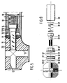
- Fig. 5 is a cross-sectional view according to Fig. 1 of a coupling piece for joining three rods, with the connector being provided in the rod end.
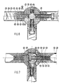
- Fig. 6 is a diagrammatic cross-sectional view of a fourth embodiment of the device according to the present invention
- Fig. 7 is a cross-sectional view according to Fig. 6 of a fifth embodiment of the device according to the present invention
- Fig. 8 shows the device according to Fig. 6 in an exploded view
- Fig. 9 shows a partly arched construction according to Fig. 7
- Fig. 10 is a partly cross-sectional perspective view of a node according to Fig. 7.
- a coupling piece 1 for joining two or more rods has four, and three coupling possibilities, respectively, for a rod (see Figs. 1, 4 and 5).
- the coupling piece is always indicated at 1 in the drawings, independently of the number of rod connection possibilities.
- Fig. 4 a single rod is shown at 2.
- the connection between coupling piece and rod is effected through a connector 3, essentially having the form of a bolt, and which is retained in a recess or through opening 4 of coupling piece 1 by means of an externally threaded nut 5 screwed onto opening 4.
- the threaded outward end 6 of the connector 3 can coact with an internally threaded bush 7 fixedly disposed in the end of rod 2.
- connector 3 takes place by a ring 8 slidable thereon prior to assembly, the through central opening of which is provided with two flat faces 9 adapted to coact with flat sides 20 provided on the connector and shown only in Fig. 5.
- the coupling piece is to be used in a linkage wherein a slightly curved surface is necessary, such as a roof, (this is also called “arching” in actual practice)
- the coacting surfaces of the head of the connector 3 and the coacting surfaces of ring 8 are provided with spherical surfaces whose centres of curvature radius lie on the axis of the respective opening of the coupling piece.
- the slight angle (between the axes of rods and coupling pieces) required for arching the construction is taken up in such a manner that a uniform connection of the coacting surfaces is ensured.
- the arching can be realized in a simple manner by using rings 8 of different thicknesses in the required places in the linkage, so that the different standard dimensions of the rods can be maintained and yet a curvature can be imparted to the linkage.
- ring 8 has recesses 10, so that the outside diameter of ring 8 may be identical to the outside diameter of rod 2 to be connected, while on the other hand, yet an easy rotation of the ring can take place by means of a known per se hook spanner.
- the coupling pieces and rods, as well as the other parts can be made of metal or synthetic plastics material.
- the coupling piece shown in Fig. 5 is provided with three connection possibilities for a rod 12. To that end, there are provided in said coupling piece three threaded openings 13.
- a bush 14 In the end of rod 12, there is welded a bush 14 whose inner end facing the free rod end is threaded so as to coact with a nut 15 serving for retaining in bush 14 a connector 16 adapted to coact with the connector 11.
- the threaded portion of connector 16 in the same manner as in the construction shown in Figs. 1 and 4, is adapted to coact by means of flats with the flat sides of a ring 17, being entirely identical to the ring 8 shown on Figs. 1-4.
- Connector 16 is retained in bush 14 on the one hand by nut 15 and on the other hand by a helical spring 18 whose other end abuts against a spring washer 19 so that the connector cannot fall out.
- the spring washer should be spaced apart from nut 15 so that the connector can be pressed so far into the rod end that the front of the connector is substantially aligned with the surface of ring 17 abutting against the coupling piece, for in that case, an easy demounting can take place.
- Fig. 6 shows a node having coupling piece 30 provided with a plurality of connection possibilities.
- the coupling piece contains a plurality of threaded openings 31 which terminate in a planar surface 32 of the spherical coupling piece 30.
- the respective connecting end thereof is first provided with an internal collar 34 which, in Fig. 6, is attached to the tube by a welded joint 35.
- a central opening 36 in collar 34 extends a bolt 37, which is retained in the tube through a spring 38 and a retaining plate 39.
- the bolt 37 has a keyway 40, so that the bolt is suitable for coaction with an inward projection 41 of a ring 42 (see Fig. 10).
- the coacting surfaces of collar 34 and the lower surface of the head of bolt 37 are spherical, while the radius of curvature of the convexity lies in the centre of the coupling.
- a further feature of the construction is that this is entirely sealed against penetration of moisture.
- the radial faces of ring 42 i.e. the faces 43, 44, are provided with annular recesses 45, 46 wherein is received an O-ring 47, 48, as clearly shown in the exploded view shown in Fig. 8.
- three of the four connection possibilities are provided with a tube 33, while the fourth connection possibility is blind by disposing a plug or stopper 49 therein.
- Fig. 7 differs only from that shown in Fig. 6 to the extent that the bolts are now received in the coupling piece, while screw thread is provided in the tube, and forging 50, respectively.
- bolt 37 has such a length that, upon complete withdrawal, i.e. the end opposite the head lies within the periphery of ring 42, it is possible to move tube 33 together with a forging 50 welded thereto in lateral direction; in other words, a rod can be replaced while the coupling piece 30 remains in place.
- Fig. 7 further shows a "normal connection" with a mounted tube, a blinded threaded hole and a loose connection with the bolt in pushed back position and tube 33 in place.
- Fig. 9 shows a part of the construction shown in Fig. 7 in arched position, i.e. one of the tubes is not co-extensive with the opposite tube but is at an angle alpha to the respective opposite tube.
- Fig. 10 depicts one connection possibility in part-sectional view, according to Fig. 7, so that it becomes clear that, due to the flat design of the lower surface 44 of ring 42 and the surface of the forging 50 facing the coupling, an easy lateral mounting and demounting is possible.
- the construction according to the present invention is simple, contains little parts and can be mounted or demounted by tightening only a single ring. This latter requires in the construction shown in Figs. 1-4 a known per se hook spanner, while for mounting or demounting the embodiments shown in the further figures, pliers are necessary, which likewise may have a very simple construction, i.e. a hooked portion and a loose portion rotatably connected thereto.
- the construction according to the present invention is externally completely smooth.
- the device is hermetically sealed, i.e. internally optimally protected against penetration of moisture and hence corrosion.
- the construction can be subjected both to compressive and tensile forces.
Landscapes
- Engineering & Computer Science (AREA)
- Architecture (AREA)
- Physics & Mathematics (AREA)
- Electromagnetism (AREA)
- Civil Engineering (AREA)
- Structural Engineering (AREA)
- Mutual Connection Of Rods And Tubes (AREA)
- Surgical Instruments (AREA)
- Load-Engaging Elements For Cranes (AREA)
Claims (5)
- Verbindungsteil (1;11;30) zum Verbinden von zwei oder mehr Stangen (2;12;33) oder dgl., bei dem ein Anschlußstück (3;16;37) verwendet wird, das drehbar mit dem Verbindungsteil (1) verbindbar ist, wobei das andere Ende des Anschlußstücks (3) durch eine Schraubverbindung (6,7;30) zum Zusammenwirken mit einem Stangenende imstande ist, wobei das Anschlußstück drehend mit einem Ring (8;17;42) zusammenwirken kann, der mit einem entsprechenden Schlüsselteil versehen ist und äußere Angreifflächen aufweist, dadurch gekennzeichnet, daß das Anschlußstück (3) einen polygonalen Außenumfangsbereich hat und der Ring (8) einen polygonalen Innenbereich hat, so daß sich das Anschlußstück drehen läßt, jedoch die Gleitbarkeit des Ringes längs des Anschlußstückes erhalten bleibt, und daß der Ring mindestens eine radiale Fläche hat, die eine ringförmige Ausnehmung (45,46) mit einem in dieser angeordneten Dichtring (47,48) aufweist, und daß die Teile zudem so bemessen sind, daß das Verbindungsteil nach dem Herstellen der Verbindung eine glatte Außenfläche hat und gegen Wasser oder anderes Fluid dicht ist.
- Verbindungsteil nach Anspruch 1, dadurch gekennzeichnet, daß die dem Verbindungsteil (37) abgewandte Ringfläche (43) und das im montierten Zustand gegen diese anliegende Stangenende sphärisch sind.
- Verbindungsteil nach Anspruch 1 oder 2, dadurch gekennzeichnet, daß das dem Zentrum des Verbindungsteiles zugewandte Ende der Mutter sowie die damit im montierten Zustand zusammenwirkende Fläche des Anschlußstückes sphärisch sind.
- Verbindungsteil nach Anspruch 2 oder 3, dadurch gekennzeichnet, daß das dem Zentrum des Verbindungsteils zugewandte Ende des Ringes und die damit im montierten Zustand zusammenwirkende Fläche des Verbindungsteils sphärisch sind.
- Verbindungsteil nach einem der Ansprüche 2, 3 oder 4, dadurch gekennzeichnet, daß das Zentrum des Krümmungsradius auf der Achse der jeweiligen Bohrung des Verbindungsteils bzw. des Rohres liegt (Fig. 9).
Priority Applications (1)
| Application Number | Priority Date | Filing Date | Title |
|---|---|---|---|
| AT87201876T ATE64969T1 (de) | 1986-10-02 | 1987-10-01 | Verbindungsvorrichtung zur verbindung zweier oder mehrerer staebe. |
Applications Claiming Priority (2)
| Application Number | Priority Date | Filing Date | Title |
|---|---|---|---|
| NL8602487A NL8602487A (nl) | 1986-10-02 | 1986-10-02 | Koppelingsstuk voor het met elkaar verbinden van twee of meer stangen. |
| NL8602487 | 1986-10-02 |
Publications (2)
| Publication Number | Publication Date |
|---|---|
| EP0265981A1 EP0265981A1 (de) | 1988-05-04 |
| EP0265981B1 true EP0265981B1 (de) | 1991-07-03 |
Family
ID=19848625
Family Applications (1)
| Application Number | Title | Priority Date | Filing Date |
|---|---|---|---|
| EP87201876A Expired - Lifetime EP0265981B1 (de) | 1986-10-02 | 1987-10-01 | Verbindungsvorrichtung zur Verbindung zweier oder mehrerer Stäbe |
Country Status (5)
| Country | Link |
|---|---|
| US (1) | US4915533A (de) |
| EP (1) | EP0265981B1 (de) |
| AT (1) | ATE64969T1 (de) |
| DE (1) | DE3771168D1 (de) |
| NL (1) | NL8602487A (de) |
Families Citing this family (24)
| Publication number | Priority date | Publication date | Assignee | Title |
|---|---|---|---|---|
| JPH0752243Y2 (ja) * | 1989-03-27 | 1995-11-29 | 川鉄建材工業株式会社 | 立体トラス用構造部材の接合装置 |
| DE8913643U1 (de) * | 1989-11-18 | 1990-02-15 | Renken, Uwe Wilhelm, 5047 Wesseling | Verbindungsstück für aus Rohren und Knotenelementen aufgebaute Konstruktionssysteme |
| DE9102252U1 (de) * | 1991-02-26 | 1991-05-16 | HEWI Heinrich Wilke GmbH, 34454 Bad Arolsen | Verbindungssystem für zwei als Rohr- oder Stangen- und/oder Knotenelemente ausgebildete Bauteile |
| GB2257173A (en) * | 1991-07-03 | 1993-01-06 | Ali Ziari | Space frame joint system. |
| DE4224697C1 (de) * | 1992-07-25 | 1993-12-16 | Mero Raumstruktur Gmbh & Co | Knotenpunktverbindung bei ebenen oder räumlichen Fachwerken aus Stäben und Knotenstücken |
| JP2652504B2 (ja) * | 1993-05-19 | 1997-09-10 | 川鉄建材株式会社 | パイプ構造材の接合装置およびその組付方法 |
| US5421666A (en) * | 1993-09-24 | 1995-06-06 | Spears; Donald L. | Pipe connector for framework fabrication |
| DE19702459A1 (de) * | 1997-01-24 | 1998-08-06 | Juergen Pauli | Verbindungselement für Rohrabschnitte |
| DE29709986U1 (de) * | 1997-06-07 | 1997-08-14 | Pauli + Sohn GmbH, 51597 Morsbach | Anschlußzapfen zur Verbindung eines Rohrabschnittes von insbesondere Treppengeländern u.dgl. mit einer Kugel |
| DE20212738U1 (de) | 2002-08-14 | 2002-10-24 | Horst Häusser Metallwaren GmbH, 73635 Rudersberg | Gewinderohrverbindungssystem |
| DE10301018B4 (de) * | 2003-01-13 | 2005-07-28 | Progress-Werk Oberkirch Ag | Anordnung zum Verbinden eines rohrförmigen ersten Bauteils mit einem zweiten Bauteil sowie Verfahren zur Herstellung einer solchen Anordnung |
| US8528291B2 (en) * | 2009-02-03 | 2013-09-10 | Allred & Associates Inc. | 3-dimensional universal tube connector system |
| US8397463B2 (en) * | 2009-02-03 | 2013-03-19 | Allred & Associates Inc. | 3-dimensional universal tube connector system |
| US8585312B1 (en) * | 2010-06-16 | 2013-11-19 | Kid Knowledge, Inc. | Three dimensional polyhedron frame structure |
| NO2883476T3 (de) * | 2013-12-13 | 2018-05-26 | ||
| CA2884194C (en) | 2014-03-05 | 2023-03-14 | 9220-6820 Quebec Inc. | Tubular structure connecting assembly |
| ES2543256B1 (es) * | 2015-02-18 | 2016-05-26 | De La Sierra Eduardo Herrezuelo | Estructura espacial |
| DE102016010883A1 (de) | 2016-09-12 | 2018-03-29 | Technische Universität Chemnitz | Variables Verbindungselement |
| USD896625S1 (en) * | 2018-07-17 | 2020-09-22 | Dongah Aluminum Corporation | Connector for modular racks |
| CN111287317B (zh) * | 2020-03-26 | 2021-06-01 | 上海杰地建筑设计有限公司 | 带双向加劲板的钢管结构树形柱分叉节点 |
| TWI770599B (zh) * | 2020-09-04 | 2022-07-11 | 賴祥瑞 | 模組化連接裝置 |
| ES1304249Y (es) * | 2023-07-13 | 2024-02-07 | Valderrama Juan Pablo Molina | Malla espacial |
| CN116729768B (zh) * | 2023-07-26 | 2026-05-12 | 航天特种材料及工艺技术研究所 | 一种飞行器包装箱并排连接结构 |
| CN117344847A (zh) * | 2023-11-09 | 2024-01-05 | 西安建筑科技大学 | 一种抗倒塌和抗震的方向可调节螺栓球节点 |
Family Cites Families (10)
| Publication number | Priority date | Publication date | Assignee | Title |
|---|---|---|---|---|
| DE874657C (de) * | 1943-03-12 | 1953-04-27 | Max Dr-Ing Mengeringhausen | Verbindung von Rohrstaeben und knotenbildenden Verbindungsstuecken, insbesondere fuer zerlegbare Fachwerkkonstruktionen |
| US4027449A (en) * | 1973-01-30 | 1977-06-07 | Alcalde Cilveti Francisco Javi | System for constructing spatial structures |
| DE2533721A1 (de) * | 1974-05-06 | 1977-02-10 | Heinz Dipl Ing Horn | Knotenpunktverbindung fuer ebene oder raeumliche fachwerke |
| DE2421758C2 (de) * | 1974-05-06 | 1975-10-16 | Heinz Dipl.-Ing. 8482 Neustadt Horn | Knotenpunktverbindung für ebene oder räumliche Fachwerke |
| FR2298720A1 (fr) * | 1975-01-27 | 1976-08-20 | Chamayou Gerard | Noeuds d'assemblage pour structures multidirectionnelles et structures comportant de tels noeuds |
| US3982841A (en) * | 1975-12-08 | 1976-09-28 | Abraham Endzweig | Connecting apparatus for frame members |
| US4161088A (en) * | 1977-11-11 | 1979-07-17 | Gugliotta Paul F | Pipe-and-ball truss array |
| DE3017444A1 (de) * | 1978-05-05 | 1981-11-12 | E. Rüter GmbH, 4600 Dortmund | Raumfachwerk |
| US4313687A (en) * | 1978-09-05 | 1982-02-02 | Juan Martinez Apeztegui | Prefabricated spatial structure |
| DE3409916A1 (de) * | 1984-03-17 | 1985-09-26 | Rolf D. 3167 Burgdorf Jachmann | Knotenpunktverbindung fuer loesbar miteinander verbindbare zylinderfoermige staebe |
-
1986
- 1986-10-02 NL NL8602487A patent/NL8602487A/nl not_active Application Discontinuation
-
1987
- 1987-09-28 US US07/101,612 patent/US4915533A/en not_active Expired - Fee Related
- 1987-10-01 EP EP87201876A patent/EP0265981B1/de not_active Expired - Lifetime
- 1987-10-01 DE DE8787201876T patent/DE3771168D1/de not_active Expired - Fee Related
- 1987-10-01 AT AT87201876T patent/ATE64969T1/de not_active IP Right Cessation
Also Published As
| Publication number | Publication date |
|---|---|
| US4915533A (en) | 1990-04-10 |
| NL8602487A (nl) | 1988-05-02 |
| EP0265981A1 (de) | 1988-05-04 |
| ATE64969T1 (de) | 1991-07-15 |
| DE3771168D1 (de) | 1991-08-08 |
Similar Documents
| Publication | Publication Date | Title |
|---|---|---|
| US4915533A (en) | Coupling piece for joining two or more rods | |
| US5083819A (en) | Fluid coupling and fastener capture device | |
| EP0575563B1 (de) | Fluidkupplung und vorrichtung zur halterung des befestigungselementes | |
| US3995962A (en) | Building kit for the production of three-dimensional frameworks | |
| US3980408A (en) | Construction element | |
| US4667928A (en) | Shut-off valve with spherical plug | |
| US5310273A (en) | Joint for truss structure | |
| US4353662A (en) | Construction system for reticulated steel structures | |
| JPH03500200A (ja) | 管体連結装置 | |
| US3141686A (en) | Pipe coupling | |
| US4915422A (en) | Pipe coupling | |
| US4626123A (en) | Connector for tubular bars and attachment members in a space framework | |
| EP0595936A1 (de) | Rohrkupplung | |
| JPH0599238A (ja) | 継手スリーブを固定するロツク装置 | |
| US4834601A (en) | Wall fastener | |
| US3653697A (en) | Prefabricated joint | |
| US6309136B1 (en) | Device for locking a mechanical member onto a shaft | |
| US4483586A (en) | Safety spacer | |
| US5039146A (en) | Tubular latch housing | |
| CA1204130A (en) | Restrained mechanical pipe joint | |
| KR102262354B1 (ko) | 관 조인트 락킹 공구 | |
| US3272536A (en) | Quick coupling device for hoses | |
| US4612551A (en) | Arrangement for the omnidirectional orientation of an antenna | |
| NZ237079A (en) | Device for connecting a rod to a framework: bolt positioned within rotatable guide sleeve | |
| DE3511056C2 (de) |
Legal Events
| Date | Code | Title | Description |
|---|---|---|---|
| PUAI | Public reference made under article 153(3) epc to a published international application that has entered the european phase |
Free format text: ORIGINAL CODE: 0009012 |
|
| AK | Designated contracting states |
Kind code of ref document: A1 Designated state(s): AT BE CH DE ES FR GB GR IT LI LU NL SE |
|
| 17P | Request for examination filed |
Effective date: 19880510 |
|
| 17Q | First examination report despatched |
Effective date: 19890217 |
|
| GRAA | (expected) grant |
Free format text: ORIGINAL CODE: 0009210 |
|
| AK | Designated contracting states |
Kind code of ref document: B1 Designated state(s): AT BE CH DE ES FR GB GR IT LI LU NL SE |
|
| PG25 | Lapsed in a contracting state [announced via postgrant information from national office to epo] |
Ref country code: SE Effective date: 19910703 Ref country code: NL Effective date: 19910703 Ref country code: IT Free format text: LAPSE BECAUSE OF FAILURE TO SUBMIT A TRANSLATION OF THE DESCRIPTION OR TO PAY THE FEE WITHIN THE PRE;WARNING: LAPSES OF ITALIAN PATENTS WITH EFFECTIVE DATE BEFORE 2007 MAY HAVE OCCURRED AT ANY TIME BEFORE 2007. THE CORRECT EFFECTIVE DATE MAY BE DIFFERENT FROM THE ONE RECORDED.SCRIBED TIME-LIMIT Effective date: 19910703 Ref country code: GR Free format text: LAPSE BECAUSE OF FAILURE TO SUBMIT A TRANSLATION OF THE DESCRIPTION OR TO PAY THE FEE WITHIN THE PRESCRIBED TIME-LIMIT Effective date: 19910703 Ref country code: FR Effective date: 19910703 Ref country code: BE Effective date: 19910703 Ref country code: AT Effective date: 19910703 |
|
| REF | Corresponds to: |
Ref document number: 64969 Country of ref document: AT Date of ref document: 19910715 Kind code of ref document: T |
|
| REF | Corresponds to: |
Ref document number: 3771168 Country of ref document: DE Date of ref document: 19910808 |
|
| PG25 | Lapsed in a contracting state [announced via postgrant information from national office to epo] |
Ref country code: GB Effective date: 19911003 |
|
| PG25 | Lapsed in a contracting state [announced via postgrant information from national office to epo] |
Ref country code: ES Free format text: LAPSE BECAUSE OF FAILURE TO SUBMIT A TRANSLATION OF THE DESCRIPTION OR TO PAY THE FEE WITHIN THE PRESCRIBED TIME-LIMIT Effective date: 19911014 |
|
| PG25 | Lapsed in a contracting state [announced via postgrant information from national office to epo] |
Ref country code: LU Free format text: LAPSE BECAUSE OF NON-PAYMENT OF DUE FEES Effective date: 19911031 Ref country code: LI Effective date: 19911031 Ref country code: CH Effective date: 19911031 |
|
| EN | Fr: translation not filed | ||
| NLV1 | Nl: lapsed or annulled due to failure to fulfill the requirements of art. 29p and 29m of the patents act | ||
| PLBE | No opposition filed within time limit |
Free format text: ORIGINAL CODE: 0009261 |
|
| STAA | Information on the status of an ep patent application or granted ep patent |
Free format text: STATUS: NO OPPOSITION FILED WITHIN TIME LIMIT |
|
| GBPC | Gb: european patent ceased through non-payment of renewal fee | ||
| 26N | No opposition filed | ||
| REG | Reference to a national code |
Ref country code: CH Ref legal event code: PL |
|
| PG25 | Lapsed in a contracting state [announced via postgrant information from national office to epo] |
Ref country code: DE Effective date: 19920701 |
|
| REG | Reference to a national code |
Ref country code: CH Ref legal event code: AUV Free format text: DAS OBENGENANNTE PATENT IST, MANGELS BEZAHLUNG DER 5. JAHRESGEBUEHR, GELOESCHT WORDEN. |