EP0266017A2 - Vorrichtung zur Verriegelung einer Stange - Google Patents
Vorrichtung zur Verriegelung einer Stange Download PDFInfo
- Publication number
- EP0266017A2 EP0266017A2 EP87304245A EP87304245A EP0266017A2 EP 0266017 A2 EP0266017 A2 EP 0266017A2 EP 87304245 A EP87304245 A EP 87304245A EP 87304245 A EP87304245 A EP 87304245A EP 0266017 A2 EP0266017 A2 EP 0266017A2
- Authority
- EP
- European Patent Office
- Prior art keywords
- ram
- nut
- housing
- rod
- ratchet teeth
- Prior art date
- Legal status (The legal status is an assumption and is not a legal conclusion. Google has not performed a legal analysis and makes no representation as to the accuracy of the status listed.)
- Granted
Links
- 239000012530 fluid Substances 0.000 claims description 15
- 230000002265 prevention Effects 0.000 claims 4
- 230000000452 restraining effect Effects 0.000 claims 2
- 238000007789 sealing Methods 0.000 claims 1
- 210000003660 reticulum Anatomy 0.000 description 6
Images


Classifications
-
- E—FIXED CONSTRUCTIONS
- E21—EARTH OR ROCK DRILLING; MINING
- E21B—EARTH OR ROCK DRILLING; OBTAINING OIL, GAS, WATER, SOLUBLE OR MELTABLE MATERIALS OR A SLURRY OF MINERALS FROM WELLS
- E21B33/00—Sealing or packing boreholes or wells
- E21B33/02—Surface sealing or packing
- E21B33/03—Well heads; Setting-up thereof
- E21B33/06—Blow-out preventers, i.e. apparatus closing around a drill pipe, e.g. annular blow-out preventers
- E21B33/061—Ram-type blow-out preventers, e.g. with pivoting rams
- E21B33/062—Ram-type blow-out preventers, e.g. with pivoting rams with sliding rams
Definitions
- the present invention relates to an improved rod locking device having particular application to locking the tail rod of a blowout preventer ram in position to prevent movement of the ram once it has been closed.
- blowout preventers When oilfield ram type blowout preventers are in use, it occasionally becomes necessary to lock the rams in the closed position.
- the prior art of blowout preventers has numerous devices for locking a ram in its closed position. Such devices range from a simple mechanical screw which is threaded through the bonnet to engage the outer end of the ram tail rod or piston to prevent its movement in the outward direction to complicated devices such as shown in U. S. Patent No. 4,305,565 wherein a locking cone responds to fluid pressure during the movement of the ram to move the locking wedges into equipment with the tapered inner surfaces of the housing.
- rod locking devices have included wedges actuated by pistons which are actuated when the rod is in its position for locking and the wedges are moved into locking engagement with a tapered surface on the rod to prevent retraction of the rod from its locked position.
- a typical example of this type of device is disclosed in U. S. Patent No. 3,208,357, issued September 28, 1965 to H. Allen et al.
- the improved rod locking device of the present invention has particular application to lock a blowout preventer ram in its closed position.
- the improved device includes a housing, a body movable in the housing, having a threaded rod and coacting with the outer end of the ram tail rod to lock it in the ram closed position, a nut rotatably mounted within said housing on the threads of the threaded rod, having ratchet teeth and a braking piston slidably mounted within said housing and having ratchet teeth engaging with the ratchet teeth of the nut, the ratchet teeth on said nut and piston allowing freedom of rotation of the nut during movement of the body into engagement with the ram tail rod and preventing rotation of the nut in the opposite direction, means for exerting pressure on said braking piston to disengage the ratchet teeth during retracting movement of the body.
- An object of the present invention is to provide an improved ram locking device which is reliable to ensure complete and prompt locking and retracting movement.
- Another object is to provide an improved ram locking device having a minimum number of moving parts.
- a further object of the present invention is to provide an improved ram locking device which ensures that the locking member is positively released and retracted from its locked position.
- Blowout preventer 10 shown in FIGURE 1 includes an improved lock 12 of the present on each of its each of its rams 14.
- Blowout preventer 10 includes the housing 16 having a central bore 18 extending therethrough and opposed, aligned guideways 20 extending outwardly form such bore 18 in which the rams 14 are positioned.
- Rams 14 are moved in guideways 20 by pressure responsive means 22, normally a piston 24 reciprocally positioned in a cylinder 26 defined within the bonnet 28.
- Tail rod 30 is secured to the outer side of piston 24 and extends through the outer end of bonnet 28 into lock housing 32 as shown.
- Lock housing 32 is suitably secured to bonnet 28 as by threads (not shown).
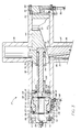
- Lock 12 is shown in FIGURES 2 and 3 in its unlocked position (FIGURE 2) and in its ram locking position (FIGURE 3).
- Lock housing 32 is generally cross-shaped with inner leg 34 connecting to bonnet 28 and receiving the outer end of tail rod 30 therein, outer leg 36 aligned with leg 34 and of sufficient size to receive the tail rod extension 38 which is secured to the outer end of tail rod 30 as shown and hereinafter described.
- the other two leg 40 and 42 of housing 32 are hollow and extend at right angles to legs 34 and 36 and are aligned with each other to allow the reciprocating movement of lock body 44 therein.
- Anti-rotation pin 37 is secured on the side of tail rod extension 38 and rides in groove 39 on the interior of leg 34 to prevent rotation of extension 38.
- legs 40 and 42 are open and closed by closure plate 46 secured to the end of leg 42 by cap screws 48 and closure plate 50 secured within leg 40 by cap screws 52 threaded into cap 54 which is held within the interior of leg 40 by snap ring 56.
- Seal ring 58 seals between leg 42 and closure plate 46.
- Body 44 reciprocates in bore 60 in leg 40 and bore 62 in leg 42 which are aligned and of the same size to allow the necessary freedom of movement of body 44 as it reciprocates therein.
- Leg 40 includes first counterbore 64, second counterbore 66, third counterbore 68 and groove 70 in which snap ring 56 is positioned.
- seal ring 72 is provided in groove 74 extending around the exterior of the portion of body 44 closet to the outer end of leg 40. Fluid is delivered through passage 76 in closure plate via fitting 78 and line 80 to the outer end of leg 42. Fluid is delivered to the outer end of leg 40 through line 82 and fitting 84 through to the interior of cap 54. Fluid is also delivered into the interior of leg 40 at counterbore 66 through line 86 and fitting 88. Passage 89 extends through tail rod extension 38 and tail rod 30 to deliver fluid to the inner or opening side of piston 24.
- Body 44 includes wedge surface 90 on its underside as shown and bore 92 through which tail rod extension 38 extends when rams 14 are in their retracted position as shown in FIGURE 2.
- Bore 94 extends into the outer end of body 44 in leg 40 and includes offset bore 96 which is provided to prevent rotation of threaded rod 98 which is held in bore 96 by snap ring 100.
- Nut 102 is threaded onto rod 98 and is supported within counterbore 64 for free rotation by bearing 104 and 106.
- Ring 108 is positioned within counterbore 64 against shoulder 110 between counterbore 64 and bore 60.
- Bearing 104 is supported in the recess 112 in ring 108 as shown.
- Flange 116 on nut 102 is positioned between bearings 104 and 106.
- Bearing 106 is positioned in recess 118 in sleeve 114 which is held in position by cap 54 which engages against the outer end of sleeve 114 as shown.
- Braking piston 120 is positioned in surrounding relationship to sleeve 114 and is provided with ratchet teeth 122 which engage with the ratchet teeth 124 in the outer end of flange 116.
- Ratchet teeth 122 and 124 are shaped to allow freedom of rotation of nut 102 during the locking movement of body 44 but to restrain against any reverse movement of body 44.
- Ratchet teeth 122 and 124 are best shown in FIGURE 4. Such teeth are square on one side and tapered at 45 degrees on the other side.
- Braking piston 120 is slidably mounted in counterbore 66 with suitable seals 126 and on the interior of cap 54 with pin 128 extending through leg 40 into slot 130 on the exterior of piston 120. Pin 128 is secured therein by cap screws 132 which extend through plate 134 into leg 40 as best seen in FIGURE 5.
- Springs 136 are positioned on the interior of cap 54 and the outer end of piston 120 to urge piston 120 so that ratchet teeth 122 and 124 are maintained in engagement. Fluid under pressure delivered through line 86 and fitting 88 is sufficient to move piston 120 to the left as shown in the drawings against the force exerted by springs 136. This movement of piston 120 is sufficient to cause the disengagement of ratchet teeth 122 and 124 and allow nut 102 to rotate freely so that body 44 is not restrained in its retracting movement from locked position.
- lock body 44 The retraction of lock body 44 is accomplished by the supplying of fluid under pressure through line 86 and fitting 88 to cause braking piston 120 to move to the left a sufficient distance to disengage its ratchet teeth 122 from ratchet teeth 124 of nut 102.
- braking piston 120 With braking piston 120 retracted by fluid pressure, fluid pressure exerted on body 44 from the interior of leg 42 causes body to retract into leg 40 so that the bore 92 in body 44 is aligned with tail rod extension 38 to ram 14 to retract ram 14 from its closed position and fluid pressure is delivered through passage 89 to piston 24.
- the advantage of the improved lock of the present invention is that the engagement of wedge surface 90 with the outer end of tail rod extension 38 ensures that the rams 14 are maintained in their closed position. Further, the nut - braking piston combination prevents retraction of body 44 until it is positively retracted responsive to fluid pressure intentionally delivered to accomplish such retraction.
Landscapes
- Geology (AREA)
- Life Sciences & Earth Sciences (AREA)
- Engineering & Computer Science (AREA)
- Mining & Mineral Resources (AREA)
- Environmental & Geological Engineering (AREA)
- Fluid Mechanics (AREA)
- Physics & Mathematics (AREA)
- General Life Sciences & Earth Sciences (AREA)
- Geochemistry & Mineralogy (AREA)
- Fluid-Damping Devices (AREA)
- Surgical Instruments (AREA)
- Load-Engaging Elements For Cranes (AREA)
- Actuator (AREA)
- Lock And Its Accessories (AREA)
- Molds, Cores, And Manufacturing Methods Thereof (AREA)
Priority Applications (1)
| Application Number | Priority Date | Filing Date | Title |
|---|---|---|---|
| AT87304245T ATE90996T1 (de) | 1986-10-27 | 1987-05-13 | Vorrichtung zur verriegelung einer stange. |
Applications Claiming Priority (2)
| Application Number | Priority Date | Filing Date | Title |
|---|---|---|---|
| US923592 | 1978-07-11 | ||
| US06/923,592 US4969627A (en) | 1986-10-27 | 1986-10-27 | Rod locking device |
Publications (3)
| Publication Number | Publication Date |
|---|---|
| EP0266017A2 true EP0266017A2 (de) | 1988-05-04 |
| EP0266017A3 EP0266017A3 (en) | 1989-05-03 |
| EP0266017B1 EP0266017B1 (de) | 1993-06-23 |
Family
ID=25448934
Family Applications (1)
| Application Number | Title | Priority Date | Filing Date |
|---|---|---|---|
| EP87304245A Expired - Lifetime EP0266017B1 (de) | 1986-10-27 | 1987-05-13 | Vorrichtung zur Verriegelung einer Stange |
Country Status (8)
| Country | Link |
|---|---|
| US (1) | US4969627A (de) |
| EP (1) | EP0266017B1 (de) |
| JP (1) | JPH0756198B2 (de) |
| AT (1) | ATE90996T1 (de) |
| BR (1) | BR8704851A (de) |
| CA (1) | CA1277591C (de) |
| DE (1) | DE3786320T2 (de) |
| NO (1) | NO874441L (de) |
Cited By (2)
| Publication number | Priority date | Publication date | Assignee | Title |
|---|---|---|---|---|
| US4969390A (en) * | 1989-05-30 | 1990-11-13 | Cooper Industries, Inc. | Rod locking device |
| EP0507027A1 (de) * | 1991-04-03 | 1992-10-07 | Cooper Cameron Corporation | Einrichtung zur Verriegelung einer Welle oder manuelle Betätigung |
Families Citing this family (23)
| Publication number | Priority date | Publication date | Assignee | Title |
|---|---|---|---|---|
| US5025708A (en) * | 1990-01-30 | 1991-06-25 | Baroid Technology, Inc. | Actuator with automatic lock |
| US5575452A (en) * | 1995-09-01 | 1996-11-19 | Varco Shaffer, Inc. | Blowout preventer with ram wedge locks |
| US5918851A (en) * | 1998-03-03 | 1999-07-06 | Cooper Cameron Corporation | Blowout preventer ram automatic locking system |
| US6006647A (en) * | 1998-05-08 | 1999-12-28 | Tuboscope I/P Inc. | Actuator with free-floating piston for a blowout preventer and the like |
| CA2311036A1 (en) | 2000-06-09 | 2001-12-09 | Oil Lift Technology Inc. | Pump drive head with leak-free stuffing box, centrifugal brake and polish rod locking clamp |
| US6969042B2 (en) * | 2004-05-01 | 2005-11-29 | Varco I/P, Inc. | Blowout preventer and ram actuator |
| US7195224B2 (en) * | 2005-02-01 | 2007-03-27 | Varco I/P, Inc. | Blowout preventer and locking mechanism |
| US20060278406A1 (en) * | 2005-06-08 | 2006-12-14 | Judge Robert A | Rod lock for ram blowout preventers |
| US7798466B2 (en) | 2007-04-27 | 2010-09-21 | Varco I/P, Inc. | Ram locking blowout preventer |
| US8844898B2 (en) | 2009-03-31 | 2014-09-30 | National Oilwell Varco, L.P. | Blowout preventer with ram socketing |
| US8544538B2 (en) | 2010-07-19 | 2013-10-01 | National Oilwell Varco, L.P. | System and method for sealing a wellbore |
| US8540017B2 (en) | 2010-07-19 | 2013-09-24 | National Oilwell Varco, L.P. | Method and system for sealing a wellbore |
| US20120055679A1 (en) * | 2010-09-08 | 2012-03-08 | Denzal Wayne Van Winkle | System and Method for Rescuing a Malfunctioning Subsea Blowout Preventer |
| US8444109B2 (en) * | 2011-02-03 | 2013-05-21 | T-3 Property Holdings, Inc. | Blowout preventer translating shaft locking system |
| KR20150092371A (ko) | 2011-03-09 | 2015-08-12 | 내셔널 오일웰 바르코 엘.피. | 유정 보어를 밀봉하기 위한 방법 및 장치 |
| WO2013155200A2 (en) | 2012-04-10 | 2013-10-17 | National Oilwell Varco, L.P. | Blowout preventer locking door assembly and method of using same |
| SG11201406397PA (en) | 2012-04-10 | 2014-11-27 | Nat Oilwell Varco Lp | Blowout preventer with locking ram assembly and method of using same |
| GB201514762D0 (en) * | 2015-08-19 | 2015-09-30 | Maritime Promeco As | Rod locking apparatus |
| WO2018056836A2 (en) | 2016-09-26 | 2018-03-29 | Maritime Promeco As | Wellbore control device |
| US10822065B2 (en) | 2017-07-28 | 2020-11-03 | Cameron International Corporation | Systems and method for buoyancy control of remotely operated underwater vehicle and payload |
| US11105174B2 (en) | 2017-07-28 | 2021-08-31 | Schlumberger Technology Corporation | Systems and method for retrievable subsea blowout preventer stack modules |
| US10900317B2 (en) * | 2017-07-28 | 2021-01-26 | Cameron International Corporation | Systems for retrievable subsea blowout preventer stack modules |
| US10767437B2 (en) * | 2018-02-01 | 2020-09-08 | Cameron International Corporation | Blowout preventer bonnet retention methods and systems |
Family Cites Families (10)
| Publication number | Priority date | Publication date | Assignee | Title |
|---|---|---|---|---|
| US1836506A (en) * | 1927-11-12 | 1931-12-15 | Chester A Rasmussen | Blow-out preventer |
| US3208357A (en) * | 1963-11-19 | 1965-09-28 | Cameron Iron Works Inc | Reciprocating piston type actuators |
| US4052995A (en) * | 1975-08-19 | 1977-10-11 | Hydril Company | Blowout preventer ram lock and locking method |
| US4076208A (en) * | 1976-10-04 | 1978-02-28 | Hydril Company | Blowout preventer ram lock |
| US4290577A (en) * | 1979-09-24 | 1981-09-22 | Hydril Company | Blowout preventer ram lock |
| US4293115A (en) * | 1979-09-24 | 1981-10-06 | Hydril Company | Testing mechanism for blowout preventer ram lock |
| US4305565A (en) * | 1980-04-07 | 1981-12-15 | Hydril Company | Variable position ram lock for blowout preventers |
| SU947389A1 (ru) * | 1980-07-28 | 1982-07-30 | Ордена Ленина И Ордена Трудового Красного Знамени Машиностроительный Завод Им.Лейт.Шмидта | Превентор |
| US4523639A (en) * | 1983-11-21 | 1985-06-18 | Koomey Blowout Preventers, Inc. | Ram type blowout preventers |
| US4601232A (en) * | 1985-03-01 | 1986-07-22 | Cameron Iron Works, Inc. | Rod locking device |
-
1986
- 1986-10-27 US US06/923,592 patent/US4969627A/en not_active Expired - Lifetime
-
1987
- 1987-05-13 AT AT87304245T patent/ATE90996T1/de not_active IP Right Cessation
- 1987-05-13 DE DE87304245T patent/DE3786320T2/de not_active Expired - Fee Related
- 1987-05-13 EP EP87304245A patent/EP0266017B1/de not_active Expired - Lifetime
- 1987-05-25 CA CA000537894A patent/CA1277591C/en not_active Expired - Lifetime
- 1987-05-29 JP JP62134750A patent/JPH0756198B2/ja not_active Expired - Lifetime
- 1987-09-22 BR BR8704851A patent/BR8704851A/pt not_active IP Right Cessation
- 1987-10-26 NO NO874441A patent/NO874441L/no unknown
Cited By (2)
| Publication number | Priority date | Publication date | Assignee | Title |
|---|---|---|---|---|
| US4969390A (en) * | 1989-05-30 | 1990-11-13 | Cooper Industries, Inc. | Rod locking device |
| EP0507027A1 (de) * | 1991-04-03 | 1992-10-07 | Cooper Cameron Corporation | Einrichtung zur Verriegelung einer Welle oder manuelle Betätigung |
Also Published As
| Publication number | Publication date |
|---|---|
| EP0266017B1 (de) | 1993-06-23 |
| CA1277591C (en) | 1990-12-11 |
| NO874441D0 (no) | 1987-10-26 |
| JPH0756198B2 (ja) | 1995-06-14 |
| BR8704851A (pt) | 1988-05-24 |
| DE3786320D1 (de) | 1993-07-29 |
| DE3786320T2 (de) | 1993-09-30 |
| ATE90996T1 (de) | 1993-07-15 |
| US4969627A (en) | 1990-11-13 |
| NO874441L (no) | 1988-04-28 |
| EP0266017A3 (en) | 1989-05-03 |
| JPS63118489A (ja) | 1988-05-23 |
Similar Documents
| Publication | Publication Date | Title |
|---|---|---|
| US4969627A (en) | Rod locking device | |
| US4601232A (en) | Rod locking device | |
| US4305565A (en) | Variable position ram lock for blowout preventers | |
| US5575452A (en) | Blowout preventer with ram wedge locks | |
| US5025708A (en) | Actuator with automatic lock | |
| US4526406A (en) | Wellhead connector | |
| US4453745A (en) | Lockdown mechanism for wellhead connector | |
| US4057267A (en) | Fluid controlled pipe connectors | |
| CA1179253A (en) | Ram-type blowout preventer | |
| US4138144A (en) | Wellhead sealing assembly | |
| US5046376A (en) | Shaft locking or manual operating apparatus | |
| US3670761A (en) | Blowout preventer with resistance means between the body and the piston | |
| DE69020966T2 (de) | Unterwasser-Futterrohrhänger und Einbauwerkzeug. | |
| DE68918696T2 (de) | Unterwasser-Verrohrungsaufhängung. | |
| CA1318243C (en) | Wellhead valve | |
| US5803689A (en) | Device for interconnection of two objects | |
| US4770250A (en) | Hydraulically actuated lock pin for well pipe hanger | |
| CN108443266B (zh) | 一种随动自锁紧增力液压油缸的随动自锁紧液压复位机构 | |
| US4697828A (en) | Wellhead body lockdown and method for engaging same | |
| US5000266A (en) | Hydraulic/torsion packoff installation tool | |
| US3520223A (en) | Quick release device with automatic reset | |
| GB2099043A (en) | Running and release tool | |
| CA2711654C (en) | Blowout preventer with lock | |
| EP0457030B1 (de) | Federspeicherzylinder für druckluftbetätigte Fahrzeugbremsen | |
| US3217610A (en) | Prong lock actuator |
Legal Events
| Date | Code | Title | Description |
|---|---|---|---|
| PUAI | Public reference made under article 153(3) epc to a published international application that has entered the european phase |
Free format text: ORIGINAL CODE: 0009012 |
|
| AK | Designated contracting states |
Kind code of ref document: A2 Designated state(s): AT DE FR GB NL |
|
| PUAL | Search report despatched |
Free format text: ORIGINAL CODE: 0009013 |
|
| AK | Designated contracting states |
Kind code of ref document: A3 Designated state(s): AT DE FR GB NL |
|
| 17P | Request for examination filed |
Effective date: 19891009 |
|
| RAP1 | Party data changed (applicant data changed or rights of an application transferred) |
Owner name: COOPER INDUSTRIES,INC. |
|
| RAP1 | Party data changed (applicant data changed or rights of an application transferred) |
Owner name: COOPER INDUSTRIES INC. |
|
| 17Q | First examination report despatched |
Effective date: 19911016 |
|
| GRAA | (expected) grant |
Free format text: ORIGINAL CODE: 0009210 |
|
| AK | Designated contracting states |
Kind code of ref document: B1 Designated state(s): AT DE FR GB NL |
|
| PG25 | Lapsed in a contracting state [announced via postgrant information from national office to epo] |
Ref country code: AT Effective date: 19930623 |
|
| REF | Corresponds to: |
Ref document number: 90996 Country of ref document: AT Date of ref document: 19930715 Kind code of ref document: T |
|
| REF | Corresponds to: |
Ref document number: 3786320 Country of ref document: DE Date of ref document: 19930729 |
|
| ET | Fr: translation filed | ||
| PLBE | No opposition filed within time limit |
Free format text: ORIGINAL CODE: 0009261 |
|
| STAA | Information on the status of an ep patent application or granted ep patent |
Free format text: STATUS: NO OPPOSITION FILED WITHIN TIME LIMIT |
|
| 26N | No opposition filed | ||
| PGFP | Annual fee paid to national office [announced via postgrant information from national office to epo] |
Ref country code: FR Payment date: 19950517 Year of fee payment: 9 |
|
| PGFP | Annual fee paid to national office [announced via postgrant information from national office to epo] |
Ref country code: NL Payment date: 19950531 Year of fee payment: 9 Ref country code: DE Payment date: 19950531 Year of fee payment: 9 |
|
| REG | Reference to a national code |
Ref country code: GB Ref legal event code: 732E |
|
| PG25 | Lapsed in a contracting state [announced via postgrant information from national office to epo] |
Ref country code: NL Effective date: 19961201 |
|
| PG25 | Lapsed in a contracting state [announced via postgrant information from national office to epo] |
Ref country code: FR Effective date: 19970131 |
|
| PG25 | Lapsed in a contracting state [announced via postgrant information from national office to epo] |
Ref country code: DE Effective date: 19970201 |
|
| NLV4 | Nl: lapsed or anulled due to non-payment of the annual fee |
Effective date: 19961201 |
|
| REG | Reference to a national code |
Ref country code: FR Ref legal event code: ST |
|
| REG | Reference to a national code |
Ref country code: GB Ref legal event code: IF02 |
|
| PGFP | Annual fee paid to national office [announced via postgrant information from national office to epo] |
Ref country code: GB Payment date: 20060406 Year of fee payment: 20 |
|
| REG | Reference to a national code |
Ref country code: GB Ref legal event code: PE20 |
|
| PG25 | Lapsed in a contracting state [announced via postgrant information from national office to epo] |
Ref country code: GB Free format text: LAPSE BECAUSE OF EXPIRATION OF PROTECTION Effective date: 20070512 |