EP0266025B1 - Durchflussmengenmesser mit veränderlichem Durchgangsquerschnitt - Google Patents
Durchflussmengenmesser mit veränderlichem Durchgangsquerschnitt Download PDFInfo
- Publication number
- EP0266025B1 EP0266025B1 EP87306629A EP87306629A EP0266025B1 EP 0266025 B1 EP0266025 B1 EP 0266025B1 EP 87306629 A EP87306629 A EP 87306629A EP 87306629 A EP87306629 A EP 87306629A EP 0266025 B1 EP0266025 B1 EP 0266025B1
- Authority
- EP
- European Patent Office
- Prior art keywords
- piston
- bore
- orifice
- flow meter
- liquid
- Prior art date
- Legal status (The legal status is an assumption and is not a legal conclusion. Google has not performed a legal analysis and makes no representation as to the accuracy of the status listed.)
- Expired
Links
- 239000007788 liquid Substances 0.000 claims abstract description 35
- 230000000903 blocking effect Effects 0.000 claims abstract description 5
- 238000006073 displacement reaction Methods 0.000 claims description 10
- 238000011144 upstream manufacturing Methods 0.000 claims description 5
- 230000000694 effects Effects 0.000 description 4
- 239000011521 glass Substances 0.000 description 4
- 239000000696 magnetic material Substances 0.000 description 2
- 239000002184 metal Substances 0.000 description 2
- 238000000034 method Methods 0.000 description 2
- 229910000831 Steel Inorganic materials 0.000 description 1
- 238000011109 contamination Methods 0.000 description 1
- 230000005484 gravity Effects 0.000 description 1
- 239000002480 mineral oil Substances 0.000 description 1
- 229920000515 polycarbonate Polymers 0.000 description 1
- 239000004417 polycarbonate Substances 0.000 description 1
- 230000036316 preload Effects 0.000 description 1
- 230000000284 resting effect Effects 0.000 description 1
- 230000035939 shock Effects 0.000 description 1
- 239000007787 solid Substances 0.000 description 1
- 239000010959 steel Substances 0.000 description 1
- 239000000126 substance Substances 0.000 description 1
Images


Classifications
-
- G—PHYSICS
- G01—MEASURING; TESTING
- G01F—MEASURING VOLUME, VOLUME FLOW, MASS FLOW OR LIQUID LEVEL; METERING BY VOLUME
- G01F1/00—Measuring the volume flow or mass flow of fluid or fluent solid material wherein the fluid passes through a meter in a continuous flow
- G01F1/05—Measuring the volume flow or mass flow of fluid or fluent solid material wherein the fluid passes through a meter in a continuous flow by using mechanical effects
- G01F1/20—Measuring the volume flow or mass flow of fluid or fluent solid material wherein the fluid passes through a meter in a continuous flow by using mechanical effects by detection of dynamic effects of the flow
- G01F1/22—Measuring the volume flow or mass flow of fluid or fluent solid material wherein the fluid passes through a meter in a continuous flow by using mechanical effects by detection of dynamic effects of the flow by variable-area meters, e.g. rotameters
- G01F1/24—Measuring the volume flow or mass flow of fluid or fluent solid material wherein the fluid passes through a meter in a continuous flow by using mechanical effects by detection of dynamic effects of the flow by variable-area meters, e.g. rotameters with magnetic or electric coupling to the indicating device
Definitions
- the invention relates to a variable orifice flow meter.
- Variable orifice flow meters are intended as simple and low-cost devices for measuring liquid flow. They comprise an orifice which is blocked by a piston held in position by a spring, or in the case of some vertical designs, by gravity. Liquid flow through the meter displaces the piston against the spring, opening up the orifice, the extent of displacement of the piston being directly proportional to the liquid flow rate.
- a flow tube in which the piston is disposed is tapered and in others the piston is tapered or suitably contoured.
- the piston is contained in a glass tube so that the displacement of the piston can be seen through the glass.
- a suitable scale can be calibrated in the required units and fixed adjacent to the glass tube so that the piston displacement can be measured directly.
- a method commonly used is to fix a magnet to the piston with a follower external to the flow tube suitably responsive to movement of the magnet and calibrated to show the flow.
- This follower can be of a magnetic material such as steel, or alternatively may itself be a linear or rotary magnet to which an indicating pointer is fixed.
- the piston is concentric with the orifice and is free to slide so that it can be easily moved by the liquid flow against the resistance provided by the spring.
- the piston is normally held centrally of the flow tube either by a central guide bar or by means of fins on the piston which are a good fit against the sides of the flow tube but with a small diametral clearance to allow it to slide freely. Displacement of the piston is primarily effected by the pressure drop across the orifice and to a lesser extent, below and critical Reynolds Number, by viscous drag on the surface area of the piston. Although a sharp edge orifice is inherently free of viscosity effects, the viscous drag (which varies with the viscosity of the liquid) will effect the piston displacement.
- EP-Al-0 171 931 describes a flow meter which comprises a body with a bore providing a straight flow passage between an inlet and an outlet and having a piston having a head capable of blocking a sharp edged orifice in the bore and a stem supported for axial movement in a guide member in the form of a tube open at both ends in said passage.
- DE-Al-2 521 952 describes a flow meter which comprises a body with bores providing a passage which extends in two directions at right angles to one another between an inlet and an outlet, a piston being provided having a head capable of blocking an orifice in the inlet part of the bore and a stem supported for axial movement in a blind bore which does not form part of the passage between the inlet and outlet.
- An object of the invention is to improve the accuracy of a variable orifice flow meter used for measuring the flow of liquids by making it less sensitive to changes in the viscosity of the liquid.
- a variable orifice liquid flow meter comprising a body, an inlet for liquid in the body, an outlet for liquid in the body, a bore in the body extending between the inlet and the outlet and defining a straight flow passage for liquid, a sharp edged orifice in the bore, a piston having a head capable of blocking the orifice and a stem by which the piston is supported for axial movement relative to the orifice, resilient means urging the piston head into a position to block the orifice, and support means located in the flow passage, in which support means the piston stem is axially slidably mounted characterised in that the support means has a blind bore in which the stem of the piston is mounted, the blind end of said blind bore being upstream of said piston head, whereby the stem is shielded from liquid flow through the bore in said body.
- the upstream end of the support means is streamlined.
- a passage is provided in the support means to permit communication by liquid in the flow tube with the portion of the piston in the blind bore.
- the support means may be fixed to the wall of the flow passage by means of fins extending radially from a generally cyindri- cal portion housing the blind bore.
- the end of the piston remote from its head is provided with an abutment ring which is slidable in the blind bore, and preferably a guide collar mounted in the blind bore adjacent to its open end is arranged slidingly to support the piston.
- Means is preferably provided for preventing axial rotation of the piston in the blind bore.
- a magnet may be fixed in the piston and arranged to drive a piston displacement indicator.
- variable orifice flow meter 37 comprising a body 3 formed as a generally rectangular solid metal block having a bore 11 extending from an inlet 24 in one end face of the body 3 to an outlet 26 in the opposite end face of the body.
- the bore 11 defines a flow tube for liquid to be metered through the body 3.
- a sharp-edged orifice ring 9 is stationarily mounted in the bore 11 of the meter 3 and is thus positioned in the flow path of the liquid.
- the orifice ring is completely blocked by the head 27 of a piston 7 disposed in the bore.
- the piston 7 is formed with a stem 29 which is axially slidably mounted centrally in the bore 11 in the blind bore 36 of a support cylinder 2.
- the support cylinder 2 comprises a central cylindrical hub 28 surrounding the stem 29 of the piston and three radial blades or fins 30 which engage the wall of the bore 11 to position the support cylinder in the bore.
- the end 39 of the hub 28 adjacent to the blind end of the bore 36 is streamlined.
- the support cylinder is held against axial movement in the bore against a shoulder 31 formed in the bore by means of a ring 4 threaded into the wall of the bore.
- abutment ring 10 is secured to the piston stem 29 by means of a circlip 1. It will be understood however that the abutment ring could be fixed in other ways.
- the piston is constantly urged into the support cylinder 2 by means of a spring 5 surrounding the piston stem 29 and engaging the abutment ring 10 and the guide collar 6 respectively.
- the free length of the spring 5 is so arranged that when contained in the support cylinder 2 it exerts a preload on the piston 7 in excess of the piston's weight, thus enabling the meter to be used in both the vertical and horizontal positions.
- the piston is prevented from rotating in the cylinder 2 by a pin 25 mounted in the guide collar 6 and which engages in a longitudinal slot 33 cut in the piston stem 29. This slot 33 also permits liquid communication between the flow tube and the blind bore and ensures that the liquid pressure acting on the piston stem is the same as the pressure on the piston immediately down stream of the support cylinder.
- Liquid flow thorugh the device pushes the piston head, which is arranged to have a smooth surface finish, through the orifice ring and opens an annular gap through which liquid can pass. If the flow rate increases, the piston is forced further through the orifice ring thus allowing a larger area through which the liquid can flow.
- the displacement of the piston can be made approximately linear with the increased flow rate.
- a cylindrical magnet 23 which is magnetised across its diameter is fixedly mounted on a shaft 22 which is supported at one end by a plain bearing in the body of the meter, the other end of the shaft 22 being supported by a deep-grooved ball bearing 38 mounted in a carrier 21 mounted in the body and which allows free rotary motion of the shaft 22 while providing axial support.
- the cylindrical magnet 23 is so positioned that movement of the longitudinal magnet 8 induces it to rotate.
- the two magnets can be considered as a rack and pinion device connected together by their magnetic fields rather than gear teeth. For this reason, the longitudinal magnet 8 cannot be allowed to rotate about its own axis since with many commercial magnets the magentic field is not evenly distributed and rotation could give a similar effect to displacement.
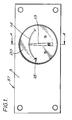
- the dial gauge 20 comprises a scale 14.
- the pointer is shown at the mid-scale position for the sake of clarity in Fig. 1, but with the orifice ring blocked by the piston, i.e. zero flow conditions, the pointer would be resting against a stop 18 at the extreme left of the scale.
- the scale is calibrated in suitable flow units and any non-linearity of the meter can be compensated for by a corresponding non-linear scale.
- a window 17, which in this case is made from clear polycarbonate, is used to protect the scale and pointer. The window is held in position by a snap ring 16.
- O-rings 15 and 19 are fitted to the scale and pointer assembly of the dial gauge, to absorb shock, to allow for some variation in tolerances of the parts and to prevent the ingress of dirt and other contamination.
- the bore 11 in body 3 has threaded ports 34, 35 at its inlet 24 and outlet 26 respectively into which suitable adaptors may be screwed for connecting the device to a pipeline.
- the flow meter is preferably mainly constructed from non-magnetic materials.
- variable orifice flow meter shown in the drawings is substantially free of viscosity effects on its accuracy, this being achieved by reducing and shielding a large part of the surface area of the piston from the liquid flow, minimising the length of the piston in contact with the liquid flow, balancing out the pressure differential along most of the piston length and ensuring a smooth finish where it is in contact with the liquid flow.
- the support cylinder could be placed down stream of the orifice ring; alternatively, two support cylinders could be used, one upstream and the other downstream of the orifice ring.
- the meter could also be modified to measure bi-directional flow by having a double-headed piston and by positioning the abutment ring 10 half way along the piston stem with a spring on either side.
Landscapes
- Physics & Mathematics (AREA)
- Fluid Mechanics (AREA)
- General Physics & Mathematics (AREA)
- Measuring Volume Flow (AREA)
- Paper (AREA)
- External Artificial Organs (AREA)
- Acyclic And Carbocyclic Compounds In Medicinal Compositions (AREA)
- Transition And Organic Metals Composition Catalysts For Addition Polymerization (AREA)
Claims (8)
Priority Applications (1)
| Application Number | Priority Date | Filing Date | Title |
|---|---|---|---|
| AT87306629T ATE60438T1 (de) | 1986-10-28 | 1987-07-28 | Durchflussmengenmesser mit veraenderlichem durchgangsquerschnitt. |
Applications Claiming Priority (2)
| Application Number | Priority Date | Filing Date | Title |
|---|---|---|---|
| GB8625705 | 1986-10-28 | ||
| GB868625705A GB8625705D0 (en) | 1986-10-28 | 1986-10-28 | Variable orifice flow meter |
Publications (2)
| Publication Number | Publication Date |
|---|---|
| EP0266025A1 EP0266025A1 (de) | 1988-05-04 |
| EP0266025B1 true EP0266025B1 (de) | 1991-01-23 |
Family
ID=10606396
Family Applications (1)
| Application Number | Title | Priority Date | Filing Date |
|---|---|---|---|
| EP87306629A Expired EP0266025B1 (de) | 1986-10-28 | 1987-07-28 | Durchflussmengenmesser mit veränderlichem Durchgangsquerschnitt |
Country Status (5)
| Country | Link |
|---|---|
| US (1) | US4840072A (de) |
| EP (1) | EP0266025B1 (de) |
| AT (1) | ATE60438T1 (de) |
| DE (1) | DE3767653D1 (de) |
| GB (1) | GB8625705D0 (de) |
Families Citing this family (7)
| Publication number | Priority date | Publication date | Assignee | Title |
|---|---|---|---|---|
| IN188196B (de) * | 1995-05-15 | 2002-08-31 | Silicon Graphics Inc | |
| DE10051869A1 (de) * | 2000-10-19 | 2002-04-25 | Wieder Gmbh | Durchflussmesser |
| WO2018013857A1 (en) | 2016-07-13 | 2018-01-18 | Rain Bird Corporation | Flow sensor |
| US10473494B2 (en) | 2017-10-24 | 2019-11-12 | Rain Bird Corporation | Flow sensor |
| US11662242B2 (en) | 2018-12-31 | 2023-05-30 | Rain Bird Corporation | Flow sensor gauge |
| US12443208B2 (en) | 2023-02-08 | 2025-10-14 | Rain Bird Corporation | Control zone devices, systems and methods |
| US12498049B2 (en) | 2024-03-29 | 2025-12-16 | Rain Bird Corporation | Zone control devices, systems and methods |
Family Cites Families (12)
| Publication number | Priority date | Publication date | Assignee | Title |
|---|---|---|---|---|
| CH193955A (de) * | 1937-02-27 | 1937-11-15 | Micafil A G Werke Fuer Electro | Durchflussmesser und Strömungsunterbruchmelder. |
| US2647402A (en) * | 1946-05-16 | 1953-08-04 | Negretti & Zambra Ltd | Flow metering mechanism |
| US2574866A (en) * | 1947-02-25 | 1951-11-13 | Henry W Fahrlander | Magnetic flow gauge |
| US2816441A (en) * | 1954-01-05 | 1957-12-17 | Freddie D Ezekiel | Variable orifice flowmeter |
| NL6409991A (de) * | 1964-08-28 | 1966-03-01 | ||
| US3910112A (en) * | 1974-05-17 | 1975-10-07 | Southwest Res Inst | Flow meter |
| US4254664A (en) * | 1979-08-03 | 1981-03-10 | Gervase Instruments Limited | Flow meters |
| US4304136A (en) * | 1980-02-01 | 1981-12-08 | Transamerica Delaval Inc. | Electrical transducer responsive to fluid flow |
| US4366718A (en) * | 1981-01-26 | 1983-01-04 | Deere & Company | Bi-directional flow transducer |
| EP0078870A1 (de) * | 1981-11-10 | 1983-05-18 | Lionel Ivor Alfred Taylor | Strömungsmesser |
| GB8305926D0 (en) * | 1983-03-03 | 1983-04-07 | Fluid Devices Ltd | Fluid flow sensors |
| GB8418151D0 (en) * | 1984-07-17 | 1984-08-22 | Hayden Nilos Conflow Ltd | Instruments with moving magnets |
-
1986
- 1986-10-28 GB GB868625705A patent/GB8625705D0/en active Pending
-
1987
- 1987-07-28 EP EP87306629A patent/EP0266025B1/de not_active Expired
- 1987-07-28 AT AT87306629T patent/ATE60438T1/de not_active IP Right Cessation
- 1987-07-28 DE DE8787306629T patent/DE3767653D1/de not_active Expired - Lifetime
- 1987-08-05 US US07/081,823 patent/US4840072A/en not_active Expired - Fee Related
Also Published As
| Publication number | Publication date |
|---|---|
| US4840072A (en) | 1989-06-20 |
| GB8625705D0 (en) | 1986-12-03 |
| ATE60438T1 (de) | 1991-02-15 |
| DE3767653D1 (de) | 1991-02-28 |
| EP0266025A1 (de) | 1988-05-04 |
Similar Documents
| Publication | Publication Date | Title |
|---|---|---|
| US4885943A (en) | Electronic flowmeter system and method | |
| US4887469A (en) | High accuracy turbine flowmeter with optical sensor | |
| US3910112A (en) | Flow meter | |
| US6591694B2 (en) | Flow meter with a self-illuminating floater | |
| CA1167283A (en) | Fluid flow meter | |
| US4840072A (en) | Variable orifice flow meter | |
| EP2827108B1 (de) | Einsetzbarer Durchflussmesser | |
| US4619139A (en) | Flow meter with displaceable flow rate indicator | |
| US4014284A (en) | Differential pressure indicators | |
| IL31278A (en) | Differential pressure measuring device | |
| US5193400A (en) | Universal rotameter | |
| US4157660A (en) | Digital flowmeter | |
| US3315523A (en) | Magnetic coupling for a flowmeter | |
| EP0171931B1 (de) | Messinstrumente mit sich bewegenden Magneten | |
| US4195518A (en) | Armored rotameter | |
| US4986133A (en) | Flow meter | |
| US3282102A (en) | Flow indicators | |
| US4428243A (en) | Flowmeters | |
| US5520058A (en) | Magnetic reluctance flowmeter | |
| US4227409A (en) | Flowmeter | |
| GB2317234A (en) | Suspended body flowmeter | |
| DE3828887C2 (de) | Prallscheiben-Strömungsmesser | |
| GB2083210A (en) | Turbine flowmeters | |
| US3691834A (en) | Variable area flow meter | |
| US2953016A (en) | Viscosimeter |
Legal Events
| Date | Code | Title | Description |
|---|---|---|---|
| PUAI | Public reference made under article 153(3) epc to a published international application that has entered the european phase |
Free format text: ORIGINAL CODE: 0009012 |
|
| AK | Designated contracting states |
Kind code of ref document: A1 Designated state(s): AT BE CH DE ES FR GB GR IT LI LU NL SE |
|
| 17P | Request for examination filed |
Effective date: 19880701 |
|
| 17Q | First examination report despatched |
Effective date: 19890929 |
|
| ITF | It: translation for a ep patent filed | ||
| GRAA | (expected) grant |
Free format text: ORIGINAL CODE: 0009210 |
|
| AK | Designated contracting states |
Kind code of ref document: B1 Designated state(s): AT BE CH DE ES FR GB GR IT LI LU NL SE |
|
| PG25 | Lapsed in a contracting state [announced via postgrant information from national office to epo] |
Ref country code: SE Effective date: 19910123 Ref country code: NL Effective date: 19910123 Ref country code: LI Effective date: 19910123 Ref country code: GR Free format text: LAPSE BECAUSE OF FAILURE TO SUBMIT A TRANSLATION OF THE DESCRIPTION OR TO PAY THE FEE WITHIN THE PRESCRIBED TIME-LIMIT Effective date: 19910123 Ref country code: CH Effective date: 19910123 Ref country code: BE Effective date: 19910123 Ref country code: AT Effective date: 19910123 |
|
| REF | Corresponds to: |
Ref document number: 60438 Country of ref document: AT Date of ref document: 19910215 Kind code of ref document: T |
|
| REF | Corresponds to: |
Ref document number: 3767653 Country of ref document: DE Date of ref document: 19910228 |
|
| ET | Fr: translation filed | ||
| PG25 | Lapsed in a contracting state [announced via postgrant information from national office to epo] |
Ref country code: ES Free format text: LAPSE BECAUSE OF FAILURE TO SUBMIT A TRANSLATION OF THE DESCRIPTION OR TO PAY THE FEE WITHIN THE PRESCRIBED TIME-LIMIT Effective date: 19910504 |
|
| REG | Reference to a national code |
Ref country code: CH Ref legal event code: PL |
|
| NLV1 | Nl: lapsed or annulled due to failure to fulfill the requirements of art. 29p and 29m of the patents act | ||
| PG25 | Lapsed in a contracting state [announced via postgrant information from national office to epo] |
Ref country code: LU Free format text: LAPSE BECAUSE OF NON-PAYMENT OF DUE FEES Effective date: 19910731 |
|
| PLBE | No opposition filed within time limit |
Free format text: ORIGINAL CODE: 0009261 |
|
| STAA | Information on the status of an ep patent application or granted ep patent |
Free format text: STATUS: NO OPPOSITION FILED WITHIN TIME LIMIT |
|
| 26N | No opposition filed | ||
| PGFP | Annual fee paid to national office [announced via postgrant information from national office to epo] |
Ref country code: GB Payment date: 19990727 Year of fee payment: 13 Ref country code: DE Payment date: 19990727 Year of fee payment: 13 |
|
| PGFP | Annual fee paid to national office [announced via postgrant information from national office to epo] |
Ref country code: FR Payment date: 19990729 Year of fee payment: 13 |
|
| PG25 | Lapsed in a contracting state [announced via postgrant information from national office to epo] |
Ref country code: GB Free format text: LAPSE BECAUSE OF NON-PAYMENT OF DUE FEES Effective date: 20000728 |
|
| GBPC | Gb: european patent ceased through non-payment of renewal fee |
Effective date: 20000728 |
|
| PG25 | Lapsed in a contracting state [announced via postgrant information from national office to epo] |
Ref country code: FR Free format text: LAPSE BECAUSE OF NON-PAYMENT OF DUE FEES Effective date: 20010330 |
|
| REG | Reference to a national code |
Ref country code: FR Ref legal event code: ST |
|
| PG25 | Lapsed in a contracting state [announced via postgrant information from national office to epo] |
Ref country code: DE Free format text: LAPSE BECAUSE OF NON-PAYMENT OF DUE FEES Effective date: 20010501 |
|
| PG25 | Lapsed in a contracting state [announced via postgrant information from national office to epo] |
Ref country code: IT Free format text: LAPSE BECAUSE OF NON-PAYMENT OF DUE FEES;WARNING: LAPSES OF ITALIAN PATENTS WITH EFFECTIVE DATE BEFORE 2007 MAY HAVE OCCURRED AT ANY TIME BEFORE 2007. THE CORRECT EFFECTIVE DATE MAY BE DIFFERENT FROM THE ONE RECORDED. Effective date: 20050728 |