EP0266085B1 - Système à voiles - Google Patents
Système à voiles Download PDFInfo
- Publication number
- EP0266085B1 EP0266085B1 EP87308989A EP87308989A EP0266085B1 EP 0266085 B1 EP0266085 B1 EP 0266085B1 EP 87308989 A EP87308989 A EP 87308989A EP 87308989 A EP87308989 A EP 87308989A EP 0266085 B1 EP0266085 B1 EP 0266085B1
- Authority
- EP
- European Patent Office
- Prior art keywords
- mast
- sail
- frame
- steering
- points
- Prior art date
- Legal status (The legal status is an assumption and is not a legal conclusion. Google has not performed a legal analysis and makes no representation as to the accuracy of the status listed.)
- Expired - Lifetime
Links
- 230000007246 mechanism Effects 0.000 claims description 20
- 230000005484 gravity Effects 0.000 claims description 8
- 230000033001 locomotion Effects 0.000 claims description 8
- 238000004804 winding Methods 0.000 claims description 2
- 210000002414 leg Anatomy 0.000 description 13
- XLYOFNOQVPJJNP-UHFFFAOYSA-N water Substances O XLYOFNOQVPJJNP-UHFFFAOYSA-N 0.000 description 11
- 230000001141 propulsive effect Effects 0.000 description 5
- 230000003321 amplification Effects 0.000 description 4
- 230000006378 damage Effects 0.000 description 4
- 230000000694 effects Effects 0.000 description 4
- 238000003199 nucleic acid amplification method Methods 0.000 description 4
- 230000001154 acute effect Effects 0.000 description 3
- 238000013459 approach Methods 0.000 description 3
- 230000009189 diving Effects 0.000 description 3
- 230000002411 adverse Effects 0.000 description 2
- 238000005452 bending Methods 0.000 description 2
- 230000006835 compression Effects 0.000 description 2
- 238000007906 compression Methods 0.000 description 2
- NJPPVKZQTLUDBO-UHFFFAOYSA-N novaluron Chemical compound C1=C(Cl)C(OC(F)(F)C(OC(F)(F)F)F)=CC=C1NC(=O)NC(=O)C1=C(F)C=CC=C1F NJPPVKZQTLUDBO-UHFFFAOYSA-N 0.000 description 2
- 239000003381 stabilizer Substances 0.000 description 2
- 210000000689 upper leg Anatomy 0.000 description 2
- 208000034699 Vitreous floaters Diseases 0.000 description 1
- 210000001015 abdomen Anatomy 0.000 description 1
- 230000000295 complement effect Effects 0.000 description 1
- 238000010276 construction Methods 0.000 description 1
- 230000003247 decreasing effect Effects 0.000 description 1
- 239000011888 foil Substances 0.000 description 1
- 210000003127 knee Anatomy 0.000 description 1
- 238000006467 substitution reaction Methods 0.000 description 1
Images


Classifications
-
- B—PERFORMING OPERATIONS; TRANSPORTING
- B63—SHIPS OR OTHER WATERBORNE VESSELS; RELATED EQUIPMENT
- B63H—MARINE PROPULSION OR STEERING
- B63H9/00—Marine propulsion provided directly by wind power
- B63H9/04—Marine propulsion provided directly by wind power using sails or like wind-catching surfaces
- B63H9/06—Types of sail; Constructional features of sails; Arrangements thereof on vessels
- B63H9/068—Sails pivotally mounted at mast tip
Definitions
- the present invention relates to an improved sailing system for light or heavy boats, canoes, surboards or the like, hereinafter generically referred to as hulls, with respect to the invention.
- Some conventional sail boats have one or more sails hanging from vertical masts so that the resultant of the wind forces is applied high above the resultant of the countering horizontal hull resistance.
- Such in a known sail system thus gives rise to large heeling and diving motions which alter the boat performance and stability. It also generates lateral torques which must be compensated by using a rudder which adds further to the water resistance.
- US-A-4,276,033 discloses a sail assembly for use with a hull, said assembly comprising: a mast base; a mast; means for mounting said mast on said base at a tilt angle with respect to the vertical axis; a sail structure connected to the tip of the mast and including a sail frame and a sail fixed at predetermined points of attachment thereon; whereby the mast is mounted on the base in such a manner as to be rotatable about the vertical axis; the sail frame is so mounted that the mast tip is at, or close to, the center of gravity of said sail; mannually operable steering means are provided on said mast adjacent said base; and rigging means including ropes are provided for operatively joining said steering means to the sail frame at points of connection on said sail frame adjacent said points of attachment, for moving said frame and sail in unison.
- the object of the present invention is to provide a sail system which avoids the above mentioned difficulties.
- the sail system comprises a sail assembly for use with a hull, said assembly comprising: a mast base; a mast; means for mounting said mast on said base for rotation of said mast about a vertical axis, said mast being so mounted as to extend at a mast tilt angle with respect to said vertical axis and having a tip at the end thereof away from said base; a sail structure including a sail frame and a sail fixed to said frame at predetermined points of attachment thereon; a universal joint mounting said sail frame on said mast tip for said mast tip to be at, or close to, the center of gravity of said sail; manually operable steering means on said mast, adjacent said base; and rigging means including ropes operatively joining said sail frame at points of connection on said sail frame adjacent said points of attachment for moving said frame and sail in unison about said universal joint when said steering means are operated, said points of connection of said ropes on said sail frame forming together a geometrical figure; said assembly being characterised in that said steering means comprise a manually operable steering frame; and
- the sail system comprises a sail assembly for use with a hull, said assembly comprising: a mast base; a mast; means for mounting said mast on said base for rotation of said mast about a vertical axis, said mast being so mounted as to extend at a mast tilt angle with respect to said vertical axis and having a tip at the end thereof away from said base; a sail structure including a sail frame and a sail fixed to said frame at predetermined points of attachment thereon; a universal joint mounting said sail frame on said mast tip for said mast tip to be at, or close to, the center of gravity of said sail; manually operable steering means on said mast, adjacent said base; and rigging means including ropes operatively joining said steering means and said sail frame at points of connection on said sail frame adjacent said points of attachment for moving said frame and sail in unison about said universal joint when said steering means are operated, said assembly being characterised in that said steering means comprise a mast plate, having rope guiding holes therethrough forming together another geometrical figure; means solidly mounting the end
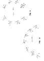
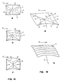
- Figure 1 is a diagrammatic top plan view of a hull provided with a sail assembly according to the invention and using a rectangular sail;
- Figures 1a and 1b being a side view and a rear view, respectively;
- Figures 2, 2a, 2b and 2c are views similar to Figures 1, 1a and 1b intended to illustrate the action of various wind forces on the sail and how the sail system according to the invention can act as a powerful hull heeling stabiliser when the sail is positioned down wind;
- Figures 3a to g are diagrammatic views illustrating a typical tacking course in association with the sail system of the invention;
- Figures 4a to h are diagrammatic views showing an outward change of course;
- Figure 5 is a perspective view of a sailing assembly mounted on a partially illustrated hull and requiring no attachment to the hull;
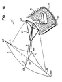
- Figure 6 is a perspective view of a sail frame and sail steering mechanism used in the sailing assembly of figure 5;
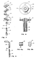
- Figure 7 is an exploded view of
- the wind forces acting on the sail are broken up into two components: one component Fn normal to the sail frame 1 and another Fw parallel to the wind direction W. Their resultant is represented by Fr. The resultant of the horizontal hull resistance is shown by Hr. Propulsive force is represented by Pf.
- the sail system basically comprises a sail 3 hung to a frame 1 to form a sail structure that hinges laterally and transversaly at the tip 5 of a mast 7 extending substantially beyond the side of a hull 9 which may be that of any floating vessel or a vessel mounted on skis for riding on ice and on wheels for riding on ground, as aforesaid.
- the mast lateral angle Ml is unlimited; the mast 7 can swing port or starboard, towards the bow or the stern of the boat.
- the mast tilt A3 is adjustable.
- the sail 3 must be kept on the leeward side of the hull 9.
- the sail 3, its frame 1, attachments and controls are primarily designed to operate with the inner side of the sail 3 exposed to windward but damages are avoided if the outer side is exposed to windward.
- a sail steering mechanism (31, fig. 6) provides quick and handy control of the sail tilt St and of the sail lateral angle Sl.
- the sail steering mechanism also provides corresponding rotation of the sail 3 around the mast axis.
- the sail 3 is tied to its frame 1 which in turn is attached to steered sets of ropes.
- the sail steering mechanism releases or pulls these ropes in such a way that the sail frame 1 remains undistorded under wide sweepage of the sail angle with the mast 7.
- the sail steering mechanism is totally supported by and mounted on the mast 7 and on a rotatable mast base (Figs. 5 and 16). In other words, the mast lateral angle Ml does not interfere with the sail steering mechanism nor with the sail trim.
- mast length requirement varies with hull stability and weight transfer associated with change of tacking course.
- An unstable hull requires a longer mast than a stable hull of same capacity because gap between level of resultant sail force Fr and level of hull lateral resistance Hr is more critical with an unstable hull.
- the sail assembly of the invention becomes a powerful stabilizer against heeling when the sail is positioned downwind and sideway with a high sail tilt St.
- the sailor has the option of managing sail tilt, sail lateral angle and mast lateral angle or locking them.
- the sailing system keeps providing forces towards equilibrium (fig 2a).
- the sail angle A5 with the horizontal wind direction W is slightly larger than the critical angle wherein the lifting force becomes nil. At such low angles, angular variations produce changes on the sail lift force several times larger than those on drag force.
- the resultant sail force Fr Focusses below the level of the resultant horizontal hull resistance, thus generating a torque towards equilibrium (fig.
- Variable mast tilt A3 is a characteristic specially attractive for hydrofoils and acrobatic sailing. As shown in figures 1, 1a and 1b, the propulsive force Pf is maximized with the sail nearly vertical and close to water level; conversely the lifting force F5 is optimized as the sail tilt St and mast tilt A3 are large. Variation of the mast tilt A3 is often accompanied with a change of sail tilt St in order to keep the resultant of the sail force Fr focussing close to level of the resultant of the hull resistance Hr. Figures 2a, 2b and 2c also show reduction of the resultant of the sail force Fr as the sail tilt St is increased; this allows the sailor to limit stresses on the equipment in case of excessive winds.
- FIGs 3a to 3g show a typical tacking course with the proposed sailing assembly.
- the mast is gradually rotated and it crosses the stern between (d) and (e).
- Figures 4a to 4h show an outward change of course. Again a gradual mast rotation is noted but this time, the mast 7 crosses the bow between (c) and (d).
- FIGS. 1a, 1b, 2a, 2b and 2c show the resultant of the sail force not focussing at the mast base level; then vertical bending moments are applied against the mast.
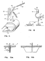
- the rectangular sail 3 shown in figures 14 and 15 is used in conjunction with the sail frame 1 shown in figures 6 and 17.
- Their forward-backward symmetry of usage allows change of tacking course without the need to rotate the sail 3 around the axis of the mast 7. With the longer side held parallel to water, the center of gravity of the rectangular sail can be set low above water surface.
- perimeter ropes 17 are each tied to two adjacent corners. Opposite sail perimeter ropes are more or less equally pulled to preserve symmetry since severe bending of the sail frame gaffs 11 would drastically reduce their resistance to compression.
- Figure 14b shows sail shape without tension applied on all perimeter ropes.
- Figures 14a, 14b and 14c show respectively the same sail 3 with low, medium and high apparent concavity.
- Figure 15 shows the effect of added siding tension ropes 19. They are threaded through eyelets 21 fixed to the sail gaffs 11. Eyelets 21 are equally distant from the terminal eyelets 13 and this distance is about the same as the distance of the siding attachments from the corner of the sail.
- Figures 15a and 15b show the effect of pulling on one set; a wing-shaped sail is then obtained.
- FIG. 5 shows a sail assembly for small hulls, requiring no attachment to the hull.
- a mast base 25, in the form of a seat for the sailor, is just deposited at the bottom of the hull and the weight of the sailing gears extending beyond the hull side is counteracted by the sailor's weight on the seat.
- the sailor grasps the steering frame, to be further described below, which gives him immediate direct control of the sail tilt, the sail lateral angle and the sail rotation around the mast axis.
- the wind force acting on the sail 3 is transmitted to the seating mast base 25.
- the sailor controls the position and the direction of the seating mast base 25 with his legs.
- the mast tilt can be changed rapidly through slipping of the seating mast base 25 across the curved bottom 27 of the hull 9.
- a worm mechanism 29 allows slow adjustment of the average mast tilt. Under normal tacking conditions, the sailor maintains the back of the seating mast base 25 close to the windward side of the hull 9 in order to lower the sail near the water surface and to counter the heeling torque generated by the keel resistance and possibly also by the sail.
- the sail steering mechanism 31 shown in figure 6 allows unlimited hinging of the sail frame 1 to the mast 7 without damage nor significant loss of control while sailing, through a hinge or universal joint 33 of the type shown in figure 7, for instance.
- Joint 33 is composed of a pair of blocks each made up of two cooperating shells 35, 37 - 39, 41, defining straight transversely arcuate beds 43, 45, each for the reception of one gaff 11; the shells being clamped and secured over the gaffs in any known manner as by screws 47 and the upper block 35, 37, being pivotely connected to the lower block 39, 41, by such means as a bolt 49 and nut 51 (through shells 37 and 39) to allow the blocks to rotate freely relative to one another about a vertical axis.
- the underface of the lowermost shell 41 has a transverse hook or eyelet 53 fixed thereto which interlaces with a U-shaped hook 55 of which the legs slide in grooves 57 across threads 58 formed at the top of a slide bar 59.
- the hook 55 is clamped in position by a ring 61 screwed over threads 58; the hooks 53, 55 and pivoted blocks 35 to 41 thus defining the universal joint 33.
- bar 59 it slidably freely lodges into an appropriate bore at the upper end of the mast 7 which then butts against the threads 58 or ring 61.
- This sub-assembly 33 thereby allows free rotation of the sail frame 1 about the mast 7 as well as hinging of the gaffs 11 by 0° to 180° with respect to the mast 7. Tension in the steering ropes near the ends of the frame gaffs 11 hold the slide bar 59 into the end bore of the mast 7.
- the sail structure frame 1, formed by the crossed gaffs 11, has a rectangular sail 3 of which the corners are fixed to attachment points 13, in the form of eyelets. As shown, the points 13 are at the corners of a rectangle the diagonals of which are the gaffs 11 and the universal joint 33 points to the center of gravity of the sail 3.
- the aforesaid steering mechanism 31 comprises a manually operable steering means 67, (fig. 5) located adjacent the base 25 and rigging means 69 which include sets of ropes operatively joining the steering means 67 and the sail structure at points of connection 71 located adjacent to the points of attachment 63 of the sail.
- the connection points 71 may, like the sail attachment points 63, be simple eyelets. With this arrangement and as will be seen further hereinafter, the steering means 67 and the rigging means 69 can move the sail frame 1 and the sail 3 in unison about the universal joint 33 when the steering means 67 is manually operated.
- the points of rope connection 71 are at the corners of a rectangle 65, shown in dotted lines in figure 6.
- the steering means 67 comprise a manually operable closed steering frame 73 (Fig. 6) which is geometrically similar to the rectangle 65 of the connection points 71. Within the plane of the frame 73, when the latter is at rest, is a sleeve 75 rotatably mounted on the mast 7 and butting against a bushing 77 fixed to the mast 7. Finally, the steering frame 73 is held in circumscribing position around the mast 7 by flexible means in the form of four tension-adjustable cable stay devices 79 connected between the sleeve 75 and the corners of the steering frame 73.
- the sleeve 75 may take the form shown in figure 10 which consists of a short hollow tube 81 having radial flanges 83 pierced with holes 85 for receiving hooks at one end of the tension adjustable cable devices 79, and for threading the said trim ropes 17 and 19.
- Rope means interconnect the steering frame 73, the sail frame 1 and the mast 7 so that motions applied to the steering frame 73 will be transmitted to the sail frame.
- Such means comprise, essentially, a pulley 91 at each corner of the steering frame 73; the second sleeve 87 of bushing arrangement 87 to 89 and rope lengths 93 each joining one point of connection 71 and the second sleeve 87 after winding around the relevant pulley 91.
- Each of the rope length 93 preferably has a portion which is part of a pulley-tackle 95 between the corresponding corner of the steering frame 73 and the second sleeve 87; the pulley-tackles 95 serving to amplify the steering movement onto the sail 3.
- the rigidity of the sail frame 1 maintains the steering ropes 93 tight which in turn hold the rotary sleeves 75 and 87 tight against the collars 77 and 89 fixed to the mast 7.
- Dotted rectangle 65 defined by the steering rope attachments 71 to the sail frame 1 is geometrically similar to the rectangle defined by the pulley attachments to the steering frame 73, as aforesaid.
- the ratio between these two rectangles and the position of the collar 89 are a set of geometric conditions related to the steering movement amplification on the sail frame 1 provided by sets of pulleys.
- the sail frame 1 and the sail steering frame 73 are practically parallel except when the sail frame 1 approaches the 0° or 180° limit with the mast.
- the sail steering frame 73 is maintained by the adjustable cable stay devices 79 and is twistable.
- the rectangular steering frame 73 has four straight bars 97 and four rigid right angular rounded elbows 99. As shown, each joint connecting one bar 97 to an adjoining elbow 99 is in the form of a terminal extension 101 of the bar 97 and of a bore 103 at one end of the elbow 99 into which the extension 101 is received for rotation. Disassembly is prevented by the provision of a suitable groove 104 and pin 105 arrangement. The steering frame 73 can thus be twisted out of a flat plane.
- the sail frame gaffs 11 can be made of collapsible tubings 106, 108 held together by waterproof tapered wedging bushing 109 in the manner shown in figure 8.
- the bushing 109 can advantageously have a free-rotating flange 111 formed with holes 113 serving for connecting the ends of the ropes 93.
- FIG. 11 One manner of mounting the mast 7 on the base 25 when the latter is free of the bottom of the hull 9 is shown in figure 11. It involves a hinge member 115 defining a hinge plate 117 and an open triangular housing 119 projecting from the plate 117. The lower end of the mast 7 is applied against the nick formed at the bottom of the triangular housing 119 and is held thereagainst by a cable tightening device 121: a collar 122 fixed to the mast 7 becomes located between the two cables 123 of the device 121 and thus prevent withdrawal of the mast 7. The end of the hinge plate 117, away from the housing 119, is mounted on the base for pivotal movement about a horizontal axis.
- the inner front end of the seat 25 is rounded to prevent injuries to the belly and the thigh of the operator and for comfort whenever knee or thigh applies sideway force to the front end of the seat.
- Low profile back seat helps the sailor to apply backward leg force directly onto the seating mast base 25.
- Figure 12 shows a seat mast base 25 ⁇ provided with a chair tilt worm mechanism 129 and a mast tilt worm mechanism 131 of the same type and function as worm mechanism 29.
- the seat base 25 ⁇ has a leg 133 and is provided with numerous leg adjustment holes for the sailor to counteract the weight of the sail and the gears extending substantially beyond the hull side.
- This seating mast base is adaptable for best comfort of the sailor with various sizes and weights.
- the seat leg 133 is freely inserted into a receiving tubular pedestal 135 anchored to the hull 9.
- the connection of the mast tilt to the hull tilt is then sturdier than with the seating mast base shown in figure 5.
- Control of the mast lateral angle for quick change of tacking course usually requires greater sailor's effort than the sail control; the receiving tubular pedestal 135 may then also include a boat steering mechanism 137 for amplification of the sailor's leg force.
- Receiving bases of seat leg 133 are preferably adjustable along longitudinal axis of the boat for easier control of mast lateral angle under various boat load conditions.
- Figure 13 shows a preferred manner of holding the seating mast base 25 ⁇ of figure 12 to a sailboard.
- the seat leg 133 is received in a tapered hole 139, near the center of the keel, which goes down below the level of the sailboard lateral resistance Hr to water.
- the resultant sail force Fr applied by the tip of the seat leg 133 below the level of sailboard lateral resistance Hr, generates a counter heeling torque that tilts the sailboard towards hydroplanning position.
- the force required to control the mast lateral angle M1 with sailboard direction is minimized with a short keel on a low profile sailboard.
- the lateral resistance to water is then concentrated near the seat leg even when sailing into waves.
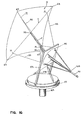
- FIGs 16, 17 and 18 show another preferred embodiment of the invention, suitable for heavier hulls, which also uses a rectangular sail 3 of which the corners are attached to the frame 1 at points 63 and the rope lengths 93 are connected at one of their ends at points 71 on the frame 1; these points 71 being thereby at the corners of a rectangle 141.
- this steering means comprise a mast plate 143 to which the mast 7 is solidly mounted at one end, by any known means, so that it projects perpendicularly from one of the faces of the mast plate 143. It will be noted that the mast 7 has an axial extension 145 (Fig. 18) that projects from the other face of the mast plate 143.
- the steering means comprise an elongated steering handle 151 connected to the mast extension 145 by a universal joint 153.
- the rigging means that operatively join the steering means and the sail structure include a sleeve 155 fixedly mounted on the handle 151 at a distance from the universal joint 153; the sleeve 155 having rope guiding eyelets 157 therearound.
- Rope-length compensating means are also provided that include discs 159 (one only being shown) located between the sleeve 155 and the mast plate 143; these discs 159 being related to the mast plate by cords 161 of which one end is fixed to the discs 159 and the other to eyelets 163 of the mast plate 143 (Fig. 18).
- rope lengths 93 each join one point of connection 71 of the sail frame 1 and one of the discs 159 after having passed through a rope guiding hole 147 of the mast plate 143 and having wound around one rope guiding element of the sleeve 155.
- each rope lengths 93 is preferably part of a pulley-tackle 165 formed between one guiding element or eyelet 157, of the sleeve 155, and the mast plate 143 where one of its pulleys is fixed to an eyelet 167.
- the mast base comprises a stationary post 169 which is anchored to the hull along its longitudinal axis with its position preferably adjustable for easier control of mast lateral angle under various load conditions.
- a round steering plateau 171 tops the post 169 and is mounted to rotate thereon about a vertical axis so that the sailor may manually control the lateral angle M1 of the mast 7.
- a steering mechanism is preferably incorporated into the plateau 171 to amplify the sailor's force.
- the mast 7 with its mast plate 143 is mounted on the base 169 and steering plateau 171 by means of hinge member 173 mounted on the plateau 171 so that it can both rotate with it about the vertical and also pivot or hinge about a horizontal axis across the plateau.
- the latter pivoting or hinging motion may be obtained by manually adjustable mechanism, such as pulley-tackles 174 disposed on either side of the hinge member 173 as shown in figure 16.
- the hinge member 173 has a flat portion and that the mast plate 143 is round and is mounted, in any convenient manner, on the flat portion for rotation about an axis normal to the said flat portion.
- FIGs 17 and 18 show complementary features of the sail assembly.
- cable stays 175 are used to maintain the mast 7 solidly normal to the mast plate 143.
- the sail frame 1 is steered by the ropes 93 guided through holes 147 of the mast plate 143 and then threaded through the sets of pulleys of the tackles 165.
- the universal joint 153 allows hinging of the steering handle 151 from 0° to 180° in any direction.
- the steering ropes 93 are kept tight by the rigidity of the sail frame 1 and by the steering assembly shown in figure 18. If the pulleys 177 of the tackles 165 were fixed to the sleeve 155, the steering ropes 93 would loosen whenever the angle 107 of a sail frame gaffs 11 with the mast 7 became very acute or very obtuse. As angle 107 of a sail frame gaff with the mast gets increasingly acute, the wire 161 approaches the sets of corresponding pulleys from the ring 155 then taking the slack in steering ropes otherwise generated. Although not shown, such a rope length compensator is also provided for set of pulleys corresponding to the other sail frame gaff.
- the rectangle 141 defined by the steering rope connections 71 to the sail frame 1 is symmetrical to the rectangle 149 defined by the rope guiding holes 147 in the mast plate 143.
- Pulley hooks 167 on the mast plate 143 are close to the corresponding guiding holes 147.
- the ratio between the rectangles 141 and 149 and the position of ring 155 on the steering handle 151 are a set of geometric conditions related to amplificati on provided by the steering pulley sets.
- the sail rotation around the axis of the mast is provided by corresponding rotation of the mast plate 143 within its support 173. This mechanism is not shown.
- rotational connection of the sail frame with the mast plate 143 is provided by tension of the steering ropes 93.
- a large sail could require unpractical dimension of the mast plate 143.
- the size of this mast plate can be reduced sizably if tortional connection between its plate and the sail steering is provided by the mast and if a high steering amplification is provided by the pulleys.
- Sail trim ropes are threaded through holes 179 of the mast plate 143 and are tied to hooks provided on a ring 184 of the steering handle 151. As all controls for sail and mast are highly centralized, this assembly is particularly attractive for automated piloting.
Landscapes
- Engineering & Computer Science (AREA)
- Life Sciences & Earth Sciences (AREA)
- Sustainable Development (AREA)
- Sustainable Energy (AREA)
- Chemical & Material Sciences (AREA)
- Combustion & Propulsion (AREA)
- Mechanical Engineering (AREA)
- Ocean & Marine Engineering (AREA)
- Toys (AREA)
Claims (15)
- Ensemble de voile destiné à être utilisé avec une coque de bateau (9), cet ensemble comprenant une embase de mât (25,169), un mât (7), des moyens (115,143) pour le montage à rotation, autour d'un axe vertical, de ce mât (7), sur l'embase (25), ce mât (7) étant monté de manière à s'étendre sous la forme d'un mât incliné d'un certain angle par rapport à l'axe vertical et ayant un sommet (5) à son extrémité éloignée de l'embase (25), une structure de voile comportant une armature de voile (1) et une voile (3) fixée à cette armature, en des points de fixation prédéterminés (63) sur celle-ci, un joint universel (33) assurant le montage de l'armature de voile (1) sur le sommet du mât (5) de manière que ce sommet (5) du mât soit situé à l'endroit du centre de gravité de la voile (3) ou à proximité immédiate de celui-ci, des moyens de pilotage actionnable manuellement (67,143) prévus sur le mât (7), à proximité immédiate de l'embase (25), et des moyens de haubanage (69) comportant des cordages (93) reliés opérationnellement à l'armature de voile (1), en des points de liaision (71), sur l'armature de voile (1), qui sont voisins des points de fixation (63), afin de déplacer l'armature et la voile, conjointement, autour du joint universel (33), lorsque les moyens de pilotage (67) sont actionnés, les points de liaison (71) des cordages et de l'armature de voile (1) formant ensemble une figure géométrique, cet ensemble étant caractérisé en ce que les moyens de pilotage (67,143) comprennent une armature de pilotage (73) actionnable manuellement et des moyens (75) pour monter cette armature de pilotage (73) sur le mât (7), de manière à permettre une rotation et un basculement libres autour de l'axe du mât, l'armature de pilotage (73) ayant des points de jonction qui forment ensemble une autre figure géométrique semblable à la précédente figure géométrique, chaque point de jonction étant associé à l'un des points de liaison (71), les haubans comprenant des longueurs de cordage (93) joignant chacune l'un des points de jonction à son point de liaison associé (71).
- Ensemble de voile suivant la revendication 1 caractérisé en ce que l'armature de pilotage (73) forme une boucle fermée, les moyens de montage de l'armature de pilotage (73) comprennent un premier manchon (75) monté sur le mât (7) de manière à pouvoir uniquement tourner librement autour de l'axe du mât, ce premier manchon étant situé dans le plan de l'armature de pilotage (73) lorsque cette armature de pilotage (73) est au repos, et des moyens flexible (79) reliant le premier manchon (75) et l'armature de pilotage (73), à l'endroit des points de jonction, et les moyens de haubanage (69) comprennent une poulie (91) située sur l'armature de pilotage (73) à l'endroit de chacun des points de jonction et un second manchon (87) monté sur le mât (7) de manière à pouvoir uniquement tourner librement autour de l'axe du mât, ce second manchon (87) étant disposé dans une position intermédiaire entre le premier manchon (75) et le joint universel (33), chacun des cordages (93) reliant l'un des points de liaison (71) et le second manchon (87) après s'être enroulé autour de l'une des poulies (91) de l'armature de pilotage.
- Ensemble de voile suivant l'une quelconque des revendications 1 ou 2 caractérisé en ce que chacun des cordages (93) comprend une longueur faisant partie d'un palan (95) entre l'un des points de jonction et le second manchon (87).
- Ensemble de voile suivant l'une quelconque des revendications 2 ou 3 caractérisé en ce que les figures géométriques sont des rectangles.
- Ensemble de voile suivant l'une quelconque des revendications 1,2 ou 3 caractérisé en ce que l'embase (25) a la forme d'un siège pour recevoir un marin et elle est adaptée de manière à reposer librement, en cours d'utilisation, sur le fond de la coque (9), si bien que la rotation du mât peut être commandée par un mouvement de ce siège.
- Ensemble de voile suivant l'une quelconque des revendications 1,2,3,4 ou 5 caractérisé en ce que les moyens (115) de montage du mât comprennent un élément articulé (115) définissant une plaque articulée (117) et un boîtier (119) faisant saillie à partir d'une extrémité de la plaque (117), des moyens (121) immobilisant d'une manière amovible, dans ce boîtier, l'extrémité du mât (7) qui est opposée à son sommet (5), des moyens (125,127) assurant le montage de l'autre extrémité de la plaque articulée (117) sur l'embase (25), pour permettre un mouvement de pivotement de cette plaque autour d'un axe horizontal, et un mécanisme (29), actionnable manuellement, entre l'embase (25) et la plaque articulée (117), ce mécanisme permettant de faire pivoter et d'ajuster le mât suivant un angle d'inclinaison prédéterminé.
- Ensemble de voile tel que revendiqué dans l'une quelconque des revendications 2 à 6, destiné à être utilisé avec une coque ayant un creux conique (139), caractérisé en ce que l'embase a une jambe en forme de tige (133) s'emboitant d'une manière amovible dans le creux (139), afin de permettre une rotation autour de l'axe vertical.
- Ensemble de voile suivant la revendication 4 caractérisé en ce que l'armature de pilotage (73) comprend quatre barres rectilignes (97), quatre coudes (99) à angle droit et des moyens pour relier les barres rectilignes (97) et les coudes (99) afin de permettre une rotation relative entre eux, autour des axes longitudinaux des barres rectilignes (97), de manière à permettre une torsion de l'armature de pilotage (73) à l'extérieur d'un plan.
- Ensemble de voile destiné à être utilisé avec une coque de bateau (9), cet ensemble comprenant une embase de mât (169), un mât (7), des moyens (115,143) pour le montage à rotation, autour d'un axe vertical, de ce mât (7), sur l'embase (169), ce mât (7) étant monté de manière à s'étendre sous la forme d'un mât incliné d'un certain angle par rapport à l'axe vertical et ayant un sommet (5) à son extrémité éloignée de l'embase (169), une structure de voile comportant une armature de voile (1) et une voile (3) fixée à cette armature, en des points de fixation prédéterminés (63) sur celle-ci, un joint universel (33) assurant le montage de l'armature de voile (1) sur le sommet du mât (5) de manière que ce sommet (5) du mât soit situé à l'endroit du centre de gravité de la voile (3) ou à proximité immédiate de celui-ci, des moyens de pilotage actionnable manuellement (67,143) prévus sur le mât (7), à proximité immédiate de l'embase (169), et des moyens de haubanage comportant des cordages (93) reliant opérationnellement les moyens de pilotage (64,173) et l'armature de voile (1), en des points de liaision (71), sur l'armature de voile (1), qui sont voisins des points de fixation, afin de déplacer l'armature et la voile, conjointement, autour du joint universel (33), lorsque les moyens de pilotage sont actionnés, cet ensemble étant caractérisé en ce que les moyens de pilotage (67,143) comprennent, une plaque de mât (143) percée de trous (147) de guidage de cordages, formant conjointement une figure géométrique, des moyens pour monter solidement l'extrémité du mât (7) qui est opposée au joint universel (33) de l'armature de voile, sur une face de la plaque de mât (143) de manière que le mât (7) s'étende perpendiculairement à partir de cette plaque, ce mât comportant un prolongement axial (145) faisant saillie à partir de l'autre face de la plaque de mât (143), une barre de pilotage allongée (151) et un autre joint universel (153) reliant une extrémité de la barre de pilotage (151) et le prolongement axial (145) du mât, en ce que les moyens de haubanage comportent en outre des moyens de fixation (155) montés sur la barre (151) à une distance prédéterminée de l'autre joint universel (153), et en ce que chacun des cordages (93) relie l'un des points de liaison de l'armature de voile aux moyens de fixation (155) après avoir passé à travers l'un des trous (147) de guidage des cordages.
- Ensemble de voile suivant la revendication 9 caractérisé en ce que les moyens de fixation comprennent un manchon (155) comportant, autour de lui, des éléments (157) de guidage des cordages et en ce que les moyens de haubanage comprennent additionnellement des moyens de compensation des cordages comportant des disques (159) entre le manchon (155) et la plaque de mât (143) et des cordes (161) fixées, à l'une de leurs extrémités, aux disques (159) et, à leurs autres extrémités, à la plaque de mât (143), à proximité immédiate du joint universel (153), chacun des cordages (93) reliant l'un des points de liaison (71) à l'un des disques (159) après avoir passé à travers l'un des trous (147) de guidage des cordages et s'être enroulé autour de l'un des éléments de guidage des cordages prévus sur le manchon (155).
- Ensemble de voile suivant la revendication 10 caractérisé en ce que chacun des cordages (93) comprend une longueur formant un palan (165) entre la plaque de mât (143) et l'un des éléments de guidage (157) prévus sur le manchon (155).
- Ensemble de voile suivant la revendication 10 caractérisé en ce que la figure géométrique est un rectangle.
- Ensemble de voile suivant l'une quelconque des revendications 11 ou 12 caractérisé en ce que l'embase (169) du mât comprend un poteau fixe (169) et un plateau (171) actionnable manuellement, lequel est monté au sommet du poteau (162) de manière à pouvoir tourner autour d'un axe vertical si bien que la rotation de ce plateau (171) commande l'angle latéral du mât (7) par l'intermédiaire des moyens (143) de montage du mât.
- Ensemble de voile suivant la revendication 13 caractérisé en ce que les moyens (143) de montage du mât comprennent un élément articulé (173) ayant une extrémité montée sur le plateau rotatif (171) de manière à pouvoir tourner avec celui-ci, cet élément (173) étant monté à rotation autour d'un axe horizontal en travers du plateau, des mécanismes (174), actionnables manuellement, disposés des deux côtés de l'élément articulé (173) et reliés à cet élément articulé (173) et au plateau (171) afin de faire pivoter l'élément articulé (173) autour de l'axe horizontal, l'élément articulé (173) a une partie plane et la plaque de mât (143) est montée sur cette partie plane de manière à pouvoir tourner autour d'un axe perpendiculaire à la partie plane de l'élément articulé.
- Ensemble de voile tel que revendiqué dans la revendication 13 ou 14, destiné à être utilisé avec une coque ayant un fond, caractérisé en ce que l'extrémité inférieur du poteau (169) est ancrée dans le fond de la coque.
Applications Claiming Priority (2)
| Application Number | Priority Date | Filing Date | Title |
|---|---|---|---|
| GB868624460A GB8624460D0 (en) | 1986-10-13 | 1986-10-13 | Sailing system |
| GB8624460 | 1986-10-13 |
Publications (2)
| Publication Number | Publication Date |
|---|---|
| EP0266085A1 EP0266085A1 (fr) | 1988-05-04 |
| EP0266085B1 true EP0266085B1 (fr) | 1991-04-24 |
Family
ID=10605636
Family Applications (1)
| Application Number | Title | Priority Date | Filing Date |
|---|---|---|---|
| EP87308989A Expired - Lifetime EP0266085B1 (fr) | 1986-10-13 | 1987-10-12 | Système à voiles |
Country Status (5)
| Country | Link |
|---|---|
| US (1) | US4788924A (fr) |
| EP (1) | EP0266085B1 (fr) |
| CA (1) | CA1288004C (fr) |
| DE (1) | DE3769589D1 (fr) |
| GB (1) | GB8624460D0 (fr) |
Families Citing this family (9)
| Publication number | Priority date | Publication date | Assignee | Title |
|---|---|---|---|---|
| FR2627449B1 (fr) * | 1988-02-23 | 1992-04-17 | Girard Marc | Voilier muni d'un dispositif de sustentation et anti-gite |
| US4936236A (en) * | 1989-03-20 | 1990-06-26 | Sinden Frank W | Symmetrical sailboat with moment balancing rig |
| US4934296A (en) * | 1989-05-03 | 1990-06-19 | Bernard Smith | Hydrofoil sailboat and method of sailing therewith |
| USD366445S (en) | 1994-12-12 | 1996-01-23 | Seggern Kurt V | Fishing boat outrigger brace |
| PL202346B1 (pl) | 2000-03-08 | 2009-06-30 | Włodzimierz Dutkiewicz | Żaglowy zespół do bezprzechyłowego napędu jednostek pływających |
| US6732670B2 (en) | 2000-06-13 | 2004-05-11 | William Richards Rayner | Sailing craft |
| FR2822802B1 (fr) * | 2001-03-29 | 2004-05-14 | Maurice Grenier | Embarcation nautique tractee par une voilure cerf-volant |
| US20060096512A1 (en) * | 2004-06-10 | 2006-05-11 | Stephen Monrad | Sailing method and system |
| US8973511B2 (en) * | 2012-03-27 | 2015-03-10 | Walter Holemans | Autonomous sailboat for oceanographic monitoring |
Family Cites Families (25)
| Publication number | Priority date | Publication date | Assignee | Title |
|---|---|---|---|---|
| CA912921A (en) * | 1972-10-24 | H. Schweitzer Henry | Wind-propelled apparatus | |
| US606104A (en) * | 1898-06-21 | twining | ||
| US2126665A (en) * | 1936-04-25 | 1938-08-09 | John T Rowland | Rig for sailboats and vessels |
| FR1156952A (fr) * | 1956-07-16 | 1958-05-23 | Perfectionnements apportés aux dispositifs de propulsion à voile | |
| FR2173389A5 (fr) * | 1972-02-22 | 1973-10-05 | Lenoble Jean Paul | |
| CA963736A (en) * | 1972-08-24 | 1975-03-04 | Earle F. Hiscock | Sail rig |
| US3870004A (en) * | 1973-12-20 | 1975-03-11 | Donald W Bailey | Sailing vessel |
| US3902443A (en) * | 1974-04-30 | 1975-09-02 | Hugh Mcdougall | Combination boat stabiliser and sail kit |
| US3981258A (en) * | 1975-07-15 | 1976-09-21 | The United States Of America As Represented By The Secretary Of The Navy | Waterski sailboat |
| US4068607A (en) * | 1976-09-10 | 1978-01-17 | Harmon G Lamar | Controllable wing sail |
| US4228750A (en) * | 1978-01-12 | 1980-10-21 | Bernard Smith | Hydrofoil sailboat with control tiller |
| US4280428A (en) * | 1978-08-07 | 1981-07-28 | Werner Jr John | Non-heeling sailboat |
| DE2917585A1 (de) * | 1979-04-30 | 1980-11-06 | Akutec Kunststofftechnik | Mastfuss fuer ein segelbrett |
| AU5858280A (en) * | 1979-05-28 | 1980-12-04 | Williams, A.M. | Sailing rig |
| US4276033A (en) * | 1979-06-18 | 1981-06-30 | Krovina Peter G | Sailing system |
| DE2938877A1 (de) * | 1979-09-26 | 1981-04-09 | Georg Dr. 4400 Münster Kassat | Windgetriebener ski |
| US4382417A (en) * | 1981-01-22 | 1983-05-10 | Harri Talve | Glider sail assembly |
| US4382418A (en) * | 1981-06-29 | 1983-05-10 | Ray Louis F | Barge unloading terminal |
| DE3276936D1 (en) * | 1982-01-06 | 1987-09-17 | Voslamber Bram J | A sail and rigging for a sailing-apparatus |
| SU1020310A1 (ru) * | 1982-01-07 | 1983-05-30 | Seleznev Nikolaj V | Парусное судно |
| US4497272A (en) * | 1982-06-01 | 1985-02-05 | Veazey Sidney E | Mastless sails |
| FR2532614A1 (fr) * | 1982-09-08 | 1984-03-09 | Guichard Philippe | Greement a voilure libre auto-pivotante |
| FR2538775A1 (fr) * | 1983-01-03 | 1984-07-06 | Perret Richard | Grement articule au centre de poussee velique |
| CA1186956A (fr) * | 1983-03-07 | 1985-05-14 | Eric Olsen | Systeme de voiles |
| US4610212A (en) * | 1985-10-11 | 1986-09-09 | Petrovich Enrique G | Fast self righting catamaran |
-
1986
- 1986-10-13 GB GB868624460A patent/GB8624460D0/en active Pending
-
1987
- 1987-10-08 CA CA000548890A patent/CA1288004C/fr not_active Expired - Lifetime
- 1987-10-08 US US07/105,616 patent/US4788924A/en not_active Expired - Lifetime
- 1987-10-12 DE DE8787308989T patent/DE3769589D1/de not_active Expired - Fee Related
- 1987-10-12 EP EP87308989A patent/EP0266085B1/fr not_active Expired - Lifetime
Also Published As
| Publication number | Publication date |
|---|---|
| AU594204B2 (en) | 1990-03-01 |
| GB8624460D0 (en) | 1986-11-19 |
| AU7954587A (en) | 1988-04-14 |
| EP0266085A1 (fr) | 1988-05-04 |
| US4788924A (en) | 1988-12-06 |
| CA1288004C (fr) | 1991-08-27 |
| DE3769589D1 (de) | 1991-05-29 |
Similar Documents
| Publication | Publication Date | Title |
|---|---|---|
| EP0284014B1 (fr) | Système de construction pour l'inclinaison du mât d'un bateau à voile vers le côté au vent | |
| US4418631A (en) | Apparatus for controlling a wind propelled sailing device | |
| US3802371A (en) | Sailing rig | |
| EP0266085B1 (fr) | Système à voiles | |
| US4473022A (en) | Sail construction | |
| US4327657A (en) | Sailing craft self-steering system | |
| US4501216A (en) | Sail and rigging for a sailing-apparatus | |
| US20010006037A1 (en) | Watersports adjustable position towing apparatus and method | |
| JPH10501775A (ja) | 反り制御帆装置 | |
| EP0070673A2 (fr) | Embarcation propulsée par le vent | |
| WO1982004236A1 (fr) | Systeme ameliore a feuille fluide | |
| US4934296A (en) | Hydrofoil sailboat and method of sailing therewith | |
| US4637332A (en) | Pivotal motor mount | |
| US4604959A (en) | Wind-propelled craft | |
| US4478164A (en) | Wind-propelled craft | |
| US4697534A (en) | Fabricated spar adapter sailing rig | |
| US4646670A (en) | Sail system for sailboards, and boardsailing apparatus and method | |
| US6655314B2 (en) | Mast step | |
| US4922845A (en) | Boom for a sailing device | |
| FR2538339A1 (fr) | Planche a voile perfectionnee | |
| US4121530A (en) | Mast base hinge for a sailboat | |
| US4261276A (en) | Sailing booms | |
| WO1983003805A1 (fr) | Systeme de voile ameliore pour planches a voile, et procede et appareil pour pratiquer la planche a voile | |
| US9399504B2 (en) | Aerodynamic wingsail | |
| JPS63500024A (ja) | 傾斜帆ヨット |
Legal Events
| Date | Code | Title | Description |
|---|---|---|---|
| PUAI | Public reference made under article 153(3) epc to a published international application that has entered the european phase |
Free format text: ORIGINAL CODE: 0009012 |
|
| AK | Designated contracting states |
Kind code of ref document: A1 Designated state(s): BE CH DE ES FR GB GR IT LI LU NL |
|
| 17P | Request for examination filed |
Effective date: 19881021 |
|
| 17Q | First examination report despatched |
Effective date: 19900118 |
|
| GRAA | (expected) grant |
Free format text: ORIGINAL CODE: 0009210 |
|
| AK | Designated contracting states |
Kind code of ref document: B1 Designated state(s): BE CH DE ES FR GB GR IT LI LU NL |
|
| PG25 | Lapsed in a contracting state [announced via postgrant information from national office to epo] |
Ref country code: GR Free format text: LAPSE BECAUSE OF FAILURE TO SUBMIT A TRANSLATION OF THE DESCRIPTION OR TO PAY THE FEE WITHIN THE PRESCRIBED TIME-LIMIT Effective date: 19910424 Ref country code: IT Free format text: LAPSE BECAUSE OF FAILURE TO SUBMIT A TRANSLATION OF THE DESCRIPTION OR TO PAY THE FEE WITHIN THE PRE;WARNING: LAPSES OF ITALIAN PATENTS WITH EFFECTIVE DATE BEFORE 2007 MAY HAVE OCCURRED AT ANY TIME BEFORE 2007. THE CORRECT EFFECTIVE DATE MAY BE DIFFERENT FROM THE ONE RECORDED.SCRIBED TIME-LIMIT Effective date: 19910424 Ref country code: NL Effective date: 19910424 |
|
| ET | Fr: translation filed | ||
| REF | Corresponds to: |
Ref document number: 3769589 Country of ref document: DE Date of ref document: 19910529 |
|
| PG25 | Lapsed in a contracting state [announced via postgrant information from national office to epo] |
Ref country code: ES Free format text: LAPSE BECAUSE OF FAILURE TO SUBMIT A TRANSLATION OF THE DESCRIPTION OR TO PAY THE FEE WITHIN THE PRESCRIBED TIME-LIMIT Effective date: 19910804 |
|
| NLV1 | Nl: lapsed or annulled due to failure to fulfill the requirements of art. 29p and 29m of the patents act | ||
| PG25 | Lapsed in a contracting state [announced via postgrant information from national office to epo] |
Ref country code: LU Free format text: LAPSE BECAUSE OF NON-PAYMENT OF DUE FEES Effective date: 19911031 |
|
| PLBE | No opposition filed within time limit |
Free format text: ORIGINAL CODE: 0009261 |
|
| STAA | Information on the status of an ep patent application or granted ep patent |
Free format text: STATUS: NO OPPOSITION FILED WITHIN TIME LIMIT |
|
| 26N | No opposition filed | ||
| PGFP | Annual fee paid to national office [announced via postgrant information from national office to epo] |
Ref country code: FR Payment date: 19940923 Year of fee payment: 8 |
|
| PGFP | Annual fee paid to national office [announced via postgrant information from national office to epo] |
Ref country code: BE Payment date: 19940927 Year of fee payment: 8 |
|
| PGFP | Annual fee paid to national office [announced via postgrant information from national office to epo] |
Ref country code: CH Payment date: 19940928 Year of fee payment: 8 Ref country code: GB Payment date: 19940928 Year of fee payment: 8 |
|
| PGFP | Annual fee paid to national office [announced via postgrant information from national office to epo] |
Ref country code: DE Payment date: 19941124 Year of fee payment: 8 |
|
| PG25 | Lapsed in a contracting state [announced via postgrant information from national office to epo] |
Ref country code: GB Effective date: 19951012 |
|
| PG25 | Lapsed in a contracting state [announced via postgrant information from national office to epo] |
Ref country code: LI Effective date: 19951031 Ref country code: CH Effective date: 19951031 Ref country code: BE Effective date: 19951031 |
|
| BERE | Be: lapsed |
Owner name: HAMEL RENALD Effective date: 19951031 |
|
| GBPC | Gb: european patent ceased through non-payment of renewal fee |
Effective date: 19951012 |
|
| REG | Reference to a national code |
Ref country code: CH Ref legal event code: PL |
|
| PG25 | Lapsed in a contracting state [announced via postgrant information from national office to epo] |
Ref country code: FR Effective date: 19960628 |
|
| PG25 | Lapsed in a contracting state [announced via postgrant information from national office to epo] |
Ref country code: DE Effective date: 19960801 |
|
| REG | Reference to a national code |
Ref country code: FR Ref legal event code: ST |