EP0266095B1 - Appareil de centrage axial pour le soudage par fusion de fibres optiques - Google Patents
Appareil de centrage axial pour le soudage par fusion de fibres optiques Download PDFInfo
- Publication number
- EP0266095B1 EP0266095B1 EP87309091A EP87309091A EP0266095B1 EP 0266095 B1 EP0266095 B1 EP 0266095B1 EP 87309091 A EP87309091 A EP 87309091A EP 87309091 A EP87309091 A EP 87309091A EP 0266095 B1 EP0266095 B1 EP 0266095B1
- Authority
- EP
- European Patent Office
- Prior art keywords
- centering
- guide
- sections
- fulcrum
- guides
- Prior art date
- Legal status (The legal status is an assumption and is not a legal conclusion. Google has not performed a legal analysis and makes no representation as to the accuracy of the status listed.)
- Expired - Lifetime
Links
- 239000013307 optical fiber Substances 0.000 title claims description 41
- 230000007246 mechanism Effects 0.000 claims description 130
- 239000000758 substrate Substances 0.000 claims description 16
- 230000003287 optical effect Effects 0.000 claims description 5
- 239000000919 ceramic Substances 0.000 claims description 4
- 239000002184 metal Substances 0.000 claims description 4
- 229910052751 metal Inorganic materials 0.000 claims description 4
- 238000006073 displacement reaction Methods 0.000 claims description 2
- 239000000463 material Substances 0.000 claims description 2
- 230000005540 biological transmission Effects 0.000 description 4
- 238000010276 construction Methods 0.000 description 3
- 239000000835 fiber Substances 0.000 description 2
- 229910000831 Steel Inorganic materials 0.000 description 1
- 239000011247 coating layer Substances 0.000 description 1
- 239000004020 conductor Substances 0.000 description 1
- 239000011521 glass Substances 0.000 description 1
- 150000002739 metals Chemical class 0.000 description 1
- 230000002093 peripheral effect Effects 0.000 description 1
- 238000005498 polishing Methods 0.000 description 1
- 239000010959 steel Substances 0.000 description 1
- 239000012780 transparent material Substances 0.000 description 1
Images





Classifications
-
- G—PHYSICS
- G02—OPTICS
- G02B—OPTICAL ELEMENTS, SYSTEMS OR APPARATUS
- G02B6/00—Light guides; Structural details of arrangements comprising light guides and other optical elements, e.g. couplings
- G02B6/24—Coupling light guides
- G02B6/36—Mechanical coupling means
-
- G—PHYSICS
- G02—OPTICS
- G02B—OPTICAL ELEMENTS, SYSTEMS OR APPARATUS
- G02B6/00—Light guides; Structural details of arrangements comprising light guides and other optical elements, e.g. couplings
- G02B6/24—Coupling light guides
- G02B6/255—Splicing of light guides, e.g. by fusion or bonding
- G02B6/2555—Alignment or adjustment devices for aligning prior to splicing
- G02B6/2557—Alignment or adjustment devices for aligning prior to splicing using deformable flexure members, flexible hinges or pivotal arms
-
- G—PHYSICS
- G02—OPTICS
- G02B—OPTICAL ELEMENTS, SYSTEMS OR APPARATUS
- G02B6/00—Light guides; Structural details of arrangements comprising light guides and other optical elements, e.g. couplings
- G02B6/24—Coupling light guides
- G02B6/36—Mechanical coupling means
- G02B6/38—Mechanical coupling means having fibre to fibre mating means
-
- G—PHYSICS
- G02—OPTICS
- G02B—OPTICAL ELEMENTS, SYSTEMS OR APPARATUS
- G02B6/00—Light guides; Structural details of arrangements comprising light guides and other optical elements, e.g. couplings
- G02B6/24—Coupling light guides
- G02B6/255—Splicing of light guides, e.g. by fusion or bonding
- G02B6/2551—Splicing of light guides, e.g. by fusion or bonding using thermal methods, e.g. fusion welding by arc discharge, laser beam, plasma torch
-
- Y—GENERAL TAGGING OF NEW TECHNOLOGICAL DEVELOPMENTS; GENERAL TAGGING OF CROSS-SECTIONAL TECHNOLOGIES SPANNING OVER SEVERAL SECTIONS OF THE IPC; TECHNICAL SUBJECTS COVERED BY FORMER USPC CROSS-REFERENCE ART COLLECTIONS [XRACs] AND DIGESTS
- Y10—TECHNICAL SUBJECTS COVERED BY FORMER USPC
- Y10S—TECHNICAL SUBJECTS COVERED BY FORMER USPC CROSS-REFERENCE ART COLLECTIONS [XRACs] AND DIGESTS
- Y10S269/00—Work holders
- Y10S269/903—Work holder for electrical circuit assemblages or wiring systems
-
- Y—GENERAL TAGGING OF NEW TECHNOLOGICAL DEVELOPMENTS; GENERAL TAGGING OF CROSS-SECTIONAL TECHNOLOGIES SPANNING OVER SEVERAL SECTIONS OF THE IPC; TECHNICAL SUBJECTS COVERED BY FORMER USPC CROSS-REFERENCE ART COLLECTIONS [XRACs] AND DIGESTS
- Y10—TECHNICAL SUBJECTS COVERED BY FORMER USPC
- Y10T—TECHNICAL SUBJECTS COVERED BY FORMER US CLASSIFICATION
- Y10T29/00—Metal working
- Y10T29/53—Means to assemble or disassemble
- Y10T29/53961—Means to assemble or disassemble with work-holder for assembly
Definitions
- This invention relates to an axially centering apparatus used for centering optical fibers to be connected in case of fusion-bonding the optical fibers end to end.
- coating layers are removed from the end portions of a pair of coated optical fibers F11 and F21 to be connected, the bare end portions F12 and F22 of the optical fibers are cut and aligned, the end portions F12 and F22 of the optical fibers are opposed at a predetermined interval of the end faces of the end portions of the optical fibers, and finely adjusted in X-axis direction and Y-axis direction.
- a guide 102B having a long groove 101B for engaging an optical fiber on the upper surface is supported through a fulcrum 104B formed on the upper inside surface of an angle type base 103B, and the center Y2 of the long groove 101B and the center Y2 of the fulcrum 104B are aligned on the same horizontal line.
- Both the centering stands 100A and 100B are opposed fixedly to align the long grooves 101A and 101B along a rectilinear line as shown in Fig. 17.
- a lateral load imparting mechanism 200 in Fig. 18 includes a motor 203 in which a gear 202 is mounted on a motor shaft 201, a rotational shaft 205 on which a gear 204 engaging with the gear 202 is mounted, a movable block 206 moving forward or reversely in the axial direction of the shaft 205 upon normal or reverse rotating of the shaft 205, a push shaft 207 provided at the end side of the block 206, and a spring 209 mounted on a push shaft 207 between the movable block 206 and a supporting plate 208, and the push shaft 207 disposed at the end side of the movable block 206 is contacted with the guide 102A of the centering stand 100A.
- the intervals of the projections 210, 211, and the pins 212, 213, 214 are set according to an empirical rule, and the interval of the overrun detecting pins 213, 214 corresponds to the moving range of the movable block 206 to be described later.
- the projections 210, 211 and the pins 212, 213, 214 respectively become electric contacts, and are electrically connected to a warning mechanism, a displaying mechanism, etc., not shown.
- the projections 210, 211 of the movable block 206 are contacted with any of the origin detecting pin 203 or the overrun detecting pins 213, 214 to notify and display the finely moving state of the guide 102A by the warning mechanism, the displaying mechanism electrically connected to them.
- the guide 102A is avoided to be displaced out of the adjusting range to be efficiently adjusted and the original position of the guide 102A is identified.
- the centering stand 100 which has been omitted for the description is associated vertically with the load imparting mechanism 200 of Fig. 18, which is used similarly to the above-mentioned operation.
- the external forces of Fx or Fy direction is applied to the guides 102A, 102B of the centerring stands 100A, 100B to be simply finely adjusted in X-axis and Y-axis directions, and the respective adjusting systems are independent from each other.
- the high adjusting accuracy is secured.
- EP-A-0216307 (which constitutes a state of the art pursuant to Art.54(3)EPC) discloses an apparatus for axially aligning a pair of optical fibres to be bonded together, the apparatus comprising a pair of centering stands for supporting the respective optical fibres, each centering stand comprising a substrate and a guide connected to the substrate by a fulcrum which extends parallel to an elongate groove formed in an upper surface of the guide, the groove being arranged to receive a said optical fibre, the apparatus further comprising a pair of centering mechanisms for the respective centering stands, each centering mechanism comprising a load imparting mechanism section having a telescopic output end contacting the guide and a transmitting mechanism section connected to an adjusting mechanism section for displacing the guide about its fulcrum, the centering stands being arranged such that an imaginary line passing through the centre of the groove and the centre of the fulcrum of one centering stand is perpendicular to an imaginary line passing through the centre of the groove and the centre of the
- each centering stand comprises a spring connected to the respective guide in order to hold the guide in contact with the telescopic output end of the respective load imparting mechanism section.
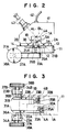
- the fulcrum 3B and the long groove 4B are relatively positioned so that the crossing angle ⁇ (beta) between a line segment LB1 and a perpendicular AL2 becomes 45° in the plane or section perpendicular to the long groove 4B, where BO1 is the center of the fulcra 3B, BO2 is the center of the long groove 4A, BL1 is the line segment for connecting both the centers BO1 and BO2, and BL2 is a perpendicular passing the center BO1 of the long groove 4B.
- the centering stands 1A and 1B may be integrally formed by cutting and polishing a metal block made, for example, of steel, but the guides 5A and 5B are ordinarily formed of ceramics at parts 5A1 and 5B1 having the long grooves 4A and 4B, of metals at the other portions 5A2 and 5B2, and the ceramic parts 5A1 and 5B2 are bonded to the metal portions 5A2 and 5B2 as apparent from Figs. 4 and 5.
- a recess 12 and two mounts 13 and 14 opposed through the recess 12 are formed on the centering stand mounting base 11, and the two centering stands 1A and 1B are disposed fixedly symmetrically on the mounts 13 and 14.
- the substrate 2A is disposed on the mount 13 of the centering stand mounting base 11, the guide 5A is disposed to be positioned in the recess 12 of the base 11, and the substrate 2A is clamped by screws to the mount 13 of the base 11.
- the substrate 2B is disposed on the mount 14 of the centering stand mounting base 11, the guide 5B is disposed to be positioned in the recess 12 of the base 11, and the substrate 2B is clamped by screws to the mount 14 of the base 11.
- the long groove 4A and 4B of both the centering stands 1A and 1B are aligned on a rectilinear line, and, as shown in Fig. 2, the line segment AL1 of the centering stand 1A and the line segment BL1 of the centering stand 1B are disposed perpendicularly to each other.
- tension type springs 21A and 21B mounted over the lower surfaces of the guides 5A and 5B and the recess 12 of the base 11 to both the centering stands 1A and 1B mounted on the base 11.
- centering mechanisms 31A and 31B having respectively load imparting mechanism sections 32A and 32B, transmitting mechanism sections 33A and 33B, and adjusting mechanism sections 34A and 34B are associated respectively with the centering stands 1A and 1B.
- the load imparting mechanism sections 32A and 32B of the centering mechanism 31A and 31B are constructed to be operated by micrometers, i.e., are respectively composed of known micrometers 39A and 39B having spindles, sleeves, thimbles, wherein output ends 35A and 35B by axially telescopic spindles are contacted with the lower surfaces of the guides 5A and 5B of the centering stands 1A and 1B.
- the transmitting mechanism sections 33A and 33B of the centering mechanisms 31A and 31B are respectively formed of transmitting levers, and respectively mounted at the ends on the base ends of the load imparting mechanism sections 32A and 32B.
- the adjusting mechanisms 34A and 34B of the centering mechanisms 31A and 31B are respectively composed of micrometers 37A and 37B having output ends 36A and 36B similarly as described above, and centering dials 38A and 38B attached to the operating ends of the micrometers 37A and 37B.
- Such adjusting mechanism sections 34A and 34B are respectively supported through supports 23A and 23B, the output ends 36A and 36B are contacted with the end of the transmitting mechanism sections 33A and 33B, and tension type springs 22A and 22B for holding the contacting states are mounted over the ends of the transmitting mechanism sections 33A and 33B and the supports 23A and 23B.
- the guide 5A of the centering stand 1A is lifted by the upward movement of the output end 35A of the micrometer 39A, and the guide 5A is finely moved obliquely upward with the fulcrum 3A as a fulcrum thereby displacing the center of the long groove 4A obliquely upward along the line segment BL1 of Fig. 2.
- the guide 5A of the centering stand 1A is moved down through the tension type spring 21A, the guide 5A is finely moved obliquely downward with the fulcrum 3A as a fulcrum, thereby displacing the center of the long groove 4A obliquely downward along the line segment AL1 in Fig. 2.
- the centering mechanism 31B is operated similarly, i.e. when the centering dial 38B of the adjusting machanism section 34B is rotated clockwise or counterclockwise, the output end 36B of the micrometer 37B of the adjusting mechanism section 34B is moved forward or backward in a predetermined direction. Thus, the output end of the micrometer 39B of the load imparting mechanism section 32B is moved upward or downward. Thus, the guide 5B of the centering stand 1B is lifted through the output end 35B, or moved down through the tension type spring 21B.
- the guide 5B is finely moved obliquely upward or downward with the fulcrum 3B as a fulcrum, and the center of the long groove 4B is displaced along the line segment AL1 of Fig. 2.
- the guides 5A and 5B of the centering stands 1A and 1B are elastically deformed through the centering mechanisms 31A and 31B to finely displace the centers of the long grooves 4A and 4B of the guides 5A and 5B in a direction along the line segments AL1 and BL1 perpendicular to each other.
- the end 2B of the optical fiber engaging within the long groove 4B of the guide 5B is moved by 0.1 micron by rotating the centering dial 38B at 26°.
- Centering stands 1A and 1B in Fig. 6-7 and 8-9 are composed, similarly to the previous embodiment, of substrates 2A and 2B, fulcra 3A and 3B, and guides 5A and 5B having long grooves 4A and 4B, respectively, which are formed of the materials similarly to those described above in the previous embodiment.
- the configurations are the same as those in the previous embodiment except that the fulcra 3A and 3B are formed on the upper surfaces of the substrates 2A and 2B, both the front and rear sides of the fulcra 3A and 3B are bent in recess shape, and the guides 5A and 5B are formed in block shape.
- centering stands 1A and 1B of these embodiments described above so mounted on the mounts 13 and 14 of the base 11 to perpendicularly cross both the line segments AL1 and BL1 described above, and the centering mechanisms 31A and 31B are associated with the centering stands 1A and 1B to contact the output ends 35A and 35B of the load imparting mechanism sections 32A and 32B with the upper surfaces of the guides 5A and 5B.
- the adjusting mechanism sections 34A and 34B of the centering mechanisms 31A and 31B may be altered to manual type as described above or may be type driven mainly by motors such as pulse motors or step motors.
- gear transmission systems are employed as the transmitting mechanism sections 33A and 33B over the motor shafts of the adjusting mechanism sections 34A and 34B and the load imparting mechanism sections 32A and 32B.
- the end faces of the spindles to become the output ends 35A, 35B and 36A, 36B of the load imparting mechanism sections 32A and 32B and the adjusting mechanism sections 34A and 34B of the centering mechanisms 31A and 31B are preferably made of spherical shape having small frictional resistances and the ends of the spindles are preferably formed of ceramics having high wear resistances.
- the means for telescoping the output ends through the micrometers may be replaced by precise threading means.
- the hoods 41 may be openable via provided hinges.
- hoods 41 are provided, for example, with illuminators 42 such as light guides, microscopes 43 for inspecting the ends of the optical fibers, the illuminators 42 and the microscopes 43 are mounted at the positions corresponding to the centers (the opposed positions of the ends of the optocal fibers) between the guides 5A and 5B so that the optical axes of the microscopes 43 are mounted on the hoods 41 with the same slope as the line segment AL1, i.e., 35°.
- axially centering mechanisms are fundamentally constructed the same as the previous embodiments except that adjusting mechanism sections 34A and 34B of centering mechanisms 31A and 31B corresponding to centering and displaying means are different from those of the above-mentioned embodiments as will be described.
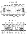
- the adjusting mechanism sections 34A and 34B respectively comprise micrometers 37A and 37B having output ends 36A and 36B of spindles, centering dials 38A and 38B attached to the operating ends of the micrometers 37A and 37B, movable bodies 60A and 60B telescoping through the micrometers 37A and 37B, guide members 51A1, 51A2 and 51B1, 51B2 for guiding the movable bodies 50A and 50B in predetermined directions, and supporting members 52A1, 52A2 and 52B1, 52B2 for supporing the guide members 51A1, 51A2 and 51B1, 51B2 at predetermined positions in predetermined states.
- Both the centering mechanism 31A and 31B made of these members are associated, as apparent in Fig. 10, with the transmitting mechanism sections 33A and 33B in symmetrical state to each other.
- the movable body 50A is penetrated through by one guide members 51A1, 51A2 installed in parallel between both supporting members 52A1 and 52A2 to be slidably supported to the guide members 51A1, 51A2 so that the output ends 36A of the micrometer 37A supported by the supporting member 52A1 and the movable body 50A are engaged by precise male and female threads formed oppositely in such a manner that one end (rear end) of the movable body 50A is contacted with the operating end of the transmitting mechanism section 33A and a tension type spring 22A is so attached to the transmitting mechanism section 33A to always contact with the movable body 50A side.
- the movable body 50A is penetrated through by one guide members 51B1, 51B2 installed in parallel between both supporting members 52B1 and 52B2 to be slidably supported to the guide members 51B1, 51B2 so that the output ends 36B of the micrometer 37B supported by the supporting member 52B1 and the movable body 50B are engaged by precise male and female threads formed oppsitely in such a manner that one end (rear end) of the movable body 50B is contacted with the operating end of the transmitting mechanism section 33B and a tension type spring 22B is so attached to the transmitting mechanism section 33B to always contact with the movable body 50B side.
- Indexes 53A and 53B made of needles are projected from the other ends (front ends) of the movable bodies 50A and 50B to correspond to displaying plate 70 to be described later.
- the interval of the operating holes 61A and 61B corresponds to that of both the centering dials 38A and 38B.
- Both the index observers 62A and 62B have lengths over the moving ranges of the indexes 53A and 53B between both the operating holes 61A and 61B.
- Both the index readers 63A and 63B display along the longitudinal directions of the index observers 63A and 63B near the index observers 62A and 63B.
- the displaying plates 60 of such construction described above are disposed fixedly at the adjusting mechanism sections 34A and 34B of the centering mechanisms 31A and 31B, and when the displaying plates 60 are fixed, the centering dials 38A and 38B are respectively engaged partly within the operating holes 61A and 61B, and the positons of the indexes 53A and 53B can be observed and read through both the index readers 63A and 63B,
- the centering mechanism 31B is operated similarly, when the centering dial 38B of the adjusting mechanism section 34B is rotated clockwise or counterclockwise, the output end 36B of the adjusting mechanism section 34B is moved forward or backward in a predetermined direction (rightward or leftward in Fig. 10).
- the movements are transmitted through the movable bodies 50B, and the transmitting mechanism section 33B to the load imparting mechanism section 32B, thereby moving upward or downward the output end 35B of the load imparting mechanism section 32B.
- the guides 5A and 5B of the centering stands 1A and 1B are elastically deformed as described above to finely displace the centers of the long grooves 4A and 4B of the guides 5A and 5B along the line segments AL1 and BL1 perpendicular to each other, thereby axially centering to bring the cores of both the optical fibers F11 and F21.
- the adjusting states of the optical fiber guides 5A and 5B can be digitally grasped on the basis of the readings to obtain suitable and rational axial centering of the optical fibers.
- the supporting members 52A2 and 52B2 of both the adjusting mechanism sections 34A and 34B may be omitted to integrate (to one unit) the two guide members 51A1, 51B1 and 51A2, 51B2.
- Both the adjusting mechanisms 34A and 34B are disposed symmetrical so that the centering dials 38A and 38B are separated to the utmost extent. However, both the centering dials 38A and 38B may be extremely symmertrical by inverting the adjusting mechanisms 34A and 34B at the right and left sides.
- the operating holes 61A and 61B are disposed between both the index observers 62A and 62B in the displaying plates 60.
- Both the adjusting mechanism sections 34A and 34B may be arranged in the state that the supporting members 52A1, 52A2, 52B1, 52B2 are disposed vertically, i.e., the supporting members 52A1, 52A2, 52B1, 52B2 may be disposed in parallel with the surface of the displaying plates 60.
- centering displaying means are formed at the centering stands of optical fiber guides, fulcra, and substrates, and may be variously employed if the centering mechanisms are associated, and such centering and displaying means may be also applied to the apparatus which employ the centering stands in Figs. 6 to 9 for those 1A and 1B.
- the operating amount from the adjusting mechanism sections may be minimized to be transmitted to the centering stands through the plurality of power transmission systems.
- the centering operation of the optical fibers can be accurately adjusted extremely finely when centering the optical fibers held by the centering stands.
- the optical fiber adjusting state can be digitally grasped in case of axially centering the optical fibers as desired, and when the optical fibers are axially centered, suitable axially centering state is obtained while accurately grasping the centering state, and the data regarding the axially centering can be collected.
Landscapes
- Physics & Mathematics (AREA)
- General Physics & Mathematics (AREA)
- Optics & Photonics (AREA)
- Engineering & Computer Science (AREA)
- Plasma & Fusion (AREA)
- Mechanical Coupling Of Light Guides (AREA)
Claims (9)
- Appareil pour aligner axialement une paire de fibres optiques destinées à être assemblées l'une à l'autre, l'appareil comprenant une paire de supports de centrage (1A, 1B) pour supporter les fibres optiques respectives, chaque support de centrage (par exemple 1A) comprenant une base (2A) et un guide (5A) relié à la base (2A), au moyen d'un pivot (3A) qui s'étend parallèlement à une gorge allongée (4A) formée dans une surface supérieure du guide (5A), la gorge (4A) étant conçue pour recevoir une fibre optique susmentionnée, l'appareil comprenant également une paire de mécanismes de centrage (31A, 31B) pour les supports de centrage (1A, 1B) respectifs, chaque mécanisme de centrage (par exemple 31A) comprenant une section formant mécanisme de chargement (32A) qui présente une extrémité de sortie télescopique (35A) en contact avec le guide (5A) et une section formant mécanisme de transmission (33A) reliée à une section formant mécanisme de réglage (34A) pour déplacer le guide (5A) sur son pivot (3A), les supports de centrage (1A, 1B) étant disposés de manière telle, qu'une ligne imaginaire (AL₁), passant par le centre (AO₂) de la gorge (4A) et le centre (AO₁) du pivot (3A) d'un support de centrage (1A), est perpendiculaire à une ligne imaginaire (BL₁) passant par le centre (BO₂) de la gorge (4B) et le centre du pivot (3B) de l'autre support de centrage (1B), chaque ligne imaginaire susmentionnée (par exemple AL₁) formant un angle de 45° par rapport à l'axe longitudinal de déplacement de ladite extrémité télescopique (35A) de la section formant mécanisme de chargement (32A) respective, dans lequel chaque support de centrage (par exemple 1A) comprend un ressort (21A) relié au guide (5A), afin de maintenir le guide (5A) en contact avec ladite extrémité de sortie télescopique (35A), de la section formant mécanisme de chargement (32A).
- Appareil de la revendication 1, caractérisé en ce que les pivots (3A, 3B) sont prévus sur les surfaces supérieures des bases respectives (2A, 2B) et les guides (5A, 5B) sont supportés par les pivots respectifs (3A, 3B).
- Appareil de la revendication 1, caractérisé en ce que les pivots (3A, 3B) sont prévus sur les faces frontales ou sur les faces arrière des bases respectives (2A, 2B) et les guides (5A, 5B) sont supportés par les pivots respectifs (3A, 3B).
- Appareil selon l'une quelconque des revendications précédentes, caractérisé en ce que des parties des guides (5A, 5B) dans lesquels sont formées les gorges (4A, 4B) sont constituées d'un matériau céramique et en ce que le reste des guides (5A, 5B), les pivots (3A, 3B) et les bases (2A, 2B) sont constitués de métal.
- Appareil selon l'une quelconque des revendications précédentes, caractérisé en ce que les mécanismes de centrage (31A, 31B) comprennent des sections formant mécanismes de réglage (34A, 34B), pour convertir le mouvement de rotation en un mouvement linéaire, les sections formant mécanismes de transmission (33A, 33B) convertissant le mouvement linéaire des sections respectives formant mécanismes de réglage en mouvement de rotation et transmettant ledit mouvement de rotation aux sections respectives formant mécanisme de chargement (32A, 32B).
- Appareil selon l'une quelconque des revendications précédentes, caractérisé en ce que les extrémités de sortie (35A, 35B) des sections formant mécanismes de chargement (32A, 32B) comprennent des broches télescopiques dans le sens axial.
- Appareil selon l'une quelconque des revendications précédentes, caractérisé en ce que les extrémités de sortie (36A, 36B) des sections formant mécanismes de réglage (34A, 34B) comprennent des broches télescopiques dans le sens axial.
- Appareil selon l'une quelconque des revendications précédentes, caractérisé en ce que les sections formant mécanismes de transmission (33A, 33B) comprennent des leviers.
- Appareil selon l'une quelconque des revendications précédentes, caractérisé en ce que des index (53A, 53B) sont prévus sur des parties mobiles des sections formant mécanismes de transmission (33A, 33B) ou de réglage (34A, 34B), l'appareil comprenant en outre des lecteurs d'index (63A, 63B), sur lesquels il est possible de lire les positions des index (53, 53B).
Applications Claiming Priority (6)
| Application Number | Priority Date | Filing Date | Title |
|---|---|---|---|
| JP25495886A JPS63108307A (ja) | 1986-10-27 | 1986-10-27 | 光フアイバ融着接続用調心台 |
| JP254960/86 | 1986-10-27 | ||
| JP254959/86 | 1986-10-27 | ||
| JP25495986A JPH0697290B2 (ja) | 1986-10-27 | 1986-10-27 | 光フアイバ融着接続用軸合わせ装置 |
| JP254958/86 | 1986-10-27 | ||
| JP25496086A JPH0697291B2 (ja) | 1986-10-27 | 1986-10-27 | 光フアイバ軸合わせ用調心表示装置 |
Publications (3)
| Publication Number | Publication Date |
|---|---|
| EP0266095A2 EP0266095A2 (fr) | 1988-05-04 |
| EP0266095A3 EP0266095A3 (en) | 1990-07-18 |
| EP0266095B1 true EP0266095B1 (fr) | 1994-05-04 |
Family
ID=27334373
Family Applications (1)
| Application Number | Title | Priority Date | Filing Date |
|---|---|---|---|
| EP87309091A Expired - Lifetime EP0266095B1 (fr) | 1986-10-27 | 1987-10-14 | Appareil de centrage axial pour le soudage par fusion de fibres optiques |
Country Status (6)
| Country | Link |
|---|---|
| US (1) | US4914797A (fr) |
| EP (1) | EP0266095B1 (fr) |
| KR (1) | KR910001289B1 (fr) |
| BR (1) | BR8705724A (fr) |
| CA (1) | CA1305852C (fr) |
| DE (1) | DE3789751T2 (fr) |
Families Citing this family (17)
| Publication number | Priority date | Publication date | Assignee | Title |
|---|---|---|---|---|
| US5002351A (en) * | 1988-07-05 | 1991-03-26 | Preformed Line Products Company | Fusion splicer for optical fibers |
| US5170456A (en) * | 1988-09-07 | 1992-12-08 | Fujikura Ltd. | Apparatus for aligning a plurality of single-fiber cables |
| US5046813A (en) * | 1988-09-07 | 1991-09-10 | Fujikura Ltd. | Method and apparatus for aligning a plurality of single-fiber cables, and method of simultaneously fusion-splicing such cables |
| FR2671409B1 (fr) * | 1991-01-08 | 1994-06-10 | Alcatel Fibres Optiques | Microsoudeuse pour fibres optiques et procede de soudage a l'aide de cette microsoudeuse. |
| GB9117761D0 (en) * | 1991-08-16 | 1991-10-02 | Bicc Plc | Optical fibre splicing |
| JP2795167B2 (ja) * | 1994-03-29 | 1998-09-10 | 住友電気工業株式会社 | 光ファイバの融着接続機 |
| JP3070406B2 (ja) * | 1994-08-18 | 2000-07-31 | 住友電気工業株式会社 | 微小駆動部材 |
| JP3168844B2 (ja) | 1994-10-13 | 2001-05-21 | 住友電気工業株式会社 | 定偏波光ファイバの融着接続方法 |
| US5524163A (en) * | 1994-12-29 | 1996-06-04 | Sumitomo Electric Industries, Ltd. | Apparatus for splicing optical fibers and method for the same |
| SE511820C2 (sv) * | 1997-05-23 | 1999-11-29 | Ericsson Telefon Ab L M | Anordning för hopsvetsning av optiska fibrer |
| US6781698B2 (en) * | 2001-06-28 | 2004-08-24 | 3M Innovative Properties Company | Quality review method for optical components using a fast system performance characterization |
| US20030053070A1 (en) * | 2001-06-28 | 2003-03-20 | 3M Innovative Properties Company | Quality review method for optical components using a fast system performance characterization |
| US6722033B2 (en) | 2001-10-08 | 2004-04-20 | Newport Corporation | Pallet assembly for assembling a fiber optic module that includes a housing |
| US7320455B2 (en) | 2003-10-24 | 2008-01-22 | Newport Corporation | Instrumented platform for vibration-sensitive equipment |
| US8231098B2 (en) * | 2004-12-07 | 2012-07-31 | Newport Corporation | Methods and devices for active vibration damping of an optical structure |
| DE102009025309B4 (de) * | 2009-06-15 | 2016-12-22 | Toptica Photonics Ag | Kinematischer Halter |
| JP5771732B1 (ja) | 2014-10-24 | 2015-09-02 | 株式会社フジクラ | 光ファイバ融着接続器及びそれを備える光ファイバ融着接続装置 |
Family Cites Families (9)
| Publication number | Priority date | Publication date | Assignee | Title |
|---|---|---|---|---|
| US2734403A (en) * | 1956-02-14 | Timpner | ||
| GB856721A (en) * | 1956-12-13 | 1960-12-21 | British Thomson Houston Co Ltd | Improvements relating to mechanical linkages |
| DE2029715C3 (de) * | 1970-06-16 | 1980-07-10 | 7517 Waldbronn | Verstelleinrichtung |
| FR2332545A1 (fr) * | 1975-11-21 | 1977-06-17 | Cit Alcatel | Support de connexions pour fibres optiques et procede pour sa mise en oeuvre |
| DE3217298A1 (de) * | 1982-05-07 | 1983-11-10 | Siemens AG, 1000 Berlin und 8000 München | Mikropositionier- und justiervorrichtung |
| JPS59111120A (ja) * | 1982-12-15 | 1984-06-27 | Furukawa Electric Co Ltd:The | 光フアイバ用軸合装置 |
| US4537466A (en) * | 1983-02-15 | 1985-08-27 | Raychem Corporation | Optical fiber chuck including a cover comprising an idler wheel and a V-shaped insert |
| DE3321988A1 (de) * | 1983-06-18 | 1984-12-20 | Standard Elektrik Lorenz Ag, 7000 Stuttgart | Vorrichtung zur spielfreien verschiebung von objekten in einem koordinatensystem |
| EP0216307A3 (fr) * | 1985-09-26 | 1989-08-02 | Siemens Aktiengesellschaft | Dispositif mécanique pour le positionnement de deux extrémités de fibres optiques |
-
1987
- 1987-10-14 EP EP87309091A patent/EP0266095B1/fr not_active Expired - Lifetime
- 1987-10-14 DE DE3789751T patent/DE3789751T2/de not_active Expired - Fee Related
- 1987-10-23 US US07/114,659 patent/US4914797A/en not_active Expired - Fee Related
- 1987-10-26 CA CA000550184A patent/CA1305852C/fr not_active Expired - Lifetime
- 1987-10-27 BR BR8705724A patent/BR8705724A/pt not_active IP Right Cessation
- 1987-10-28 KR KR1019870011962A patent/KR910001289B1/ko not_active Expired
Also Published As
| Publication number | Publication date |
|---|---|
| DE3789751T2 (de) | 1994-12-22 |
| EP0266095A2 (fr) | 1988-05-04 |
| EP0266095A3 (en) | 1990-07-18 |
| US4914797A (en) | 1990-04-10 |
| DE3789751D1 (de) | 1994-06-09 |
| KR880005472A (ko) | 1988-06-29 |
| KR910001289B1 (ko) | 1991-02-28 |
| BR8705724A (pt) | 1988-05-31 |
| CA1305852C (fr) | 1992-08-04 |
Similar Documents
| Publication | Publication Date | Title |
|---|---|---|
| EP0266095B1 (fr) | Appareil de centrage axial pour le soudage par fusion de fibres optiques | |
| US5168617A (en) | Axially centering apparatus for fusion-bonding optical fibers | |
| US4239330A (en) | Multiple optical switch | |
| EP3521881B1 (fr) | Connecteur optique | |
| US5583691A (en) | Multi-axes stage | |
| JPH0282212A (ja) | 光スイッチ | |
| US4537466A (en) | Optical fiber chuck including a cover comprising an idler wheel and a V-shaped insert | |
| US20030202737A1 (en) | Optical switch | |
| KR900008299B1 (ko) | 광파이버 특성의 측정방법 및 장치 | |
| JP2000089141A (ja) | 光ファイバスイッチ | |
| US6704477B2 (en) | Optical switch | |
| JP2519233B2 (ja) | 光フアイバ用多心一括切替スイツチ | |
| US6328481B1 (en) | Arrayed optical fiber connector | |
| JPS63108309A (ja) | 光フアイバ軸合わせ用調心表示装置 | |
| CN2546896Y (zh) | 机械式光学转换装置 | |
| GB2224129A (en) | Optical matrix | |
| JP2620321B2 (ja) | 光スイッチ | |
| CN2560957Y (zh) | 多路光开关 | |
| JP3237728B2 (ja) | 多心光ファイバ心線接続装置 | |
| CN210945384U (zh) | 一种用于光纤的简易连接推微弯装置 | |
| CN2543085Y (zh) | 机械式光学开关 | |
| JP3481853B2 (ja) | 光ファイバの個別調心装置 | |
| JP2002139684A (ja) | 光スイッチ装置 | |
| JPH07104454B2 (ja) | 光ファイバ用調心台の調心操作機構 | |
| JP2023127023A (ja) | 光アダプタ |
Legal Events
| Date | Code | Title | Description |
|---|---|---|---|
| PUAI | Public reference made under article 153(3) epc to a published international application that has entered the european phase |
Free format text: ORIGINAL CODE: 0009012 |
|
| AK | Designated contracting states |
Kind code of ref document: A2 Designated state(s): DE FR GB IT |
|
| PUAL | Search report despatched |
Free format text: ORIGINAL CODE: 0009013 |
|
| AK | Designated contracting states |
Kind code of ref document: A3 Designated state(s): DE FR GB IT |
|
| 17P | Request for examination filed |
Effective date: 19901212 |
|
| 17Q | First examination report despatched |
Effective date: 19920731 |
|
| GRAA | (expected) grant |
Free format text: ORIGINAL CODE: 0009210 |
|
| RAP1 | Party data changed (applicant data changed or rights of an application transferred) |
Owner name: THE FURUKAWA ELECTRIC CO., LTD. |
|
| AK | Designated contracting states |
Kind code of ref document: B1 Designated state(s): DE FR GB IT |
|
| REF | Corresponds to: |
Ref document number: 3789751 Country of ref document: DE Date of ref document: 19940609 |
|
| ITF | It: translation for a ep patent filed | ||
| ET | Fr: translation filed | ||
| PLBE | No opposition filed within time limit |
Free format text: ORIGINAL CODE: 0009261 |
|
| STAA | Information on the status of an ep patent application or granted ep patent |
Free format text: STATUS: NO OPPOSITION FILED WITHIN TIME LIMIT |
|
| 26N | No opposition filed | ||
| PGFP | Annual fee paid to national office [announced via postgrant information from national office to epo] |
Ref country code: FR Payment date: 19981009 Year of fee payment: 12 |
|
| PGFP | Annual fee paid to national office [announced via postgrant information from national office to epo] |
Ref country code: GB Payment date: 19981016 Year of fee payment: 12 |
|
| PGFP | Annual fee paid to national office [announced via postgrant information from national office to epo] |
Ref country code: DE Payment date: 19981023 Year of fee payment: 12 |
|
| PG25 | Lapsed in a contracting state [announced via postgrant information from national office to epo] |
Ref country code: GB Free format text: LAPSE BECAUSE OF NON-PAYMENT OF DUE FEES Effective date: 19991014 |
|
| GBPC | Gb: european patent ceased through non-payment of renewal fee |
Effective date: 19991014 |
|
| PG25 | Lapsed in a contracting state [announced via postgrant information from national office to epo] |
Ref country code: FR Free format text: LAPSE BECAUSE OF NON-PAYMENT OF DUE FEES Effective date: 20000630 |
|
| PG25 | Lapsed in a contracting state [announced via postgrant information from national office to epo] |
Ref country code: DE Free format text: LAPSE BECAUSE OF NON-PAYMENT OF DUE FEES Effective date: 20000801 |
|
| REG | Reference to a national code |
Ref country code: FR Ref legal event code: ST |
|
| PG25 | Lapsed in a contracting state [announced via postgrant information from national office to epo] |
Ref country code: IT Free format text: LAPSE BECAUSE OF NON-PAYMENT OF DUE FEES;WARNING: LAPSES OF ITALIAN PATENTS WITH EFFECTIVE DATE BEFORE 2007 MAY HAVE OCCURRED AT ANY TIME BEFORE 2007. THE CORRECT EFFECTIVE DATE MAY BE DIFFERENT FROM THE ONE RECORDED. Effective date: 20051014 |