EP0266103A2 - Magnetischer Streuflussfühler zur zerstörungsfreien Prüfung - Google Patents
Magnetischer Streuflussfühler zur zerstörungsfreien Prüfung Download PDFInfo
- Publication number
- EP0266103A2 EP0266103A2 EP87309183A EP87309183A EP0266103A2 EP 0266103 A2 EP0266103 A2 EP 0266103A2 EP 87309183 A EP87309183 A EP 87309183A EP 87309183 A EP87309183 A EP 87309183A EP 0266103 A2 EP0266103 A2 EP 0266103A2
- Authority
- EP
- European Patent Office
- Prior art keywords
- coil
- probe
- magnetic
- housing
- magnetic flux
- Prior art date
- Legal status (The legal status is an assumption and is not a legal conclusion. Google has not performed a legal analysis and makes no representation as to the accuracy of the status listed.)
- Granted
Links
Images


Classifications
-
- G—PHYSICS
- G01—MEASURING; TESTING
- G01N—INVESTIGATING OR ANALYSING MATERIALS BY DETERMINING THEIR CHEMICAL OR PHYSICAL PROPERTIES
- G01N27/00—Investigating or analysing materials by the use of electric, electrochemical, or magnetic means
- G01N27/72—Investigating or analysing materials by the use of electric, electrochemical, or magnetic means by investigating magnetic variables
- G01N27/82—Investigating or analysing materials by the use of electric, electrochemical, or magnetic means by investigating magnetic variables for investigating the presence of flaws
Definitions
- This invention relates generally to nondestructive testing of pipe and tubing using magnetic flux leakage inspection, and more particularly the invention relates to a probe for use in such testing.
- a magnetic field is established in the material undergoing inspection, and a sensor detects changes in flux patterns at the surface of the material due to cracks, pits, or wall thickness variations.
- eddy current coil detectors have been employed to detect sharp responses due to defects such as cracks and pits, while Hall effect sensors have been employed to detect more gradual responses due to wall thinning, for example.
- An object of the invention is an improved probe for use in nondestructive testing of ferritic stainless steel and carbon steel tubing.
- Another object of the invention is a magnetic flux leakage probe which is responsive to both sharp and gradual magnetic flux changes due to material defects.
- Still another object of the invention is a probe that is readily manufactured and used for nondestructive in-service inspection of pipe and tubing.
- a feature of the invention is the use of a plurality of flux leakage coil sensors positioned in a probe for different spacing from a surface undergoing inspection.
- Another feature of the invention is the use of flux leakage coils which are configured to respond to radial components of flux leakage at the inner surfaces of tubes and pipes.
- Still another feature of the invention is the provision of a Hall-effect sensor along with flux leakage coil sensors to facilitate the detection of gradual changes due to wall thickness variations, for example.
- a probe in accordance with the invention includes a generally cylindrical housing in which is mounted magnetic means for establishing a flux pattern in the body of a tube or pipe undergoing inspection.
- a plurality of coils is mounted in the housing at different radii whereby the coils are spaced differently from the inner surface of the material undergoing inspection.
- Comparison of signals from the two coils facilitates identification of the damage point and the approximate severity of the damage.
- Each coil is designed to provide a response to the perpendicular or radial component of flux leakage produced around a defect.
- a Hall-effect sensor is provided in the probe and spaced from the flux leakage sensing coils for detecting flux changes due to wall thickness variations.
- sharp response effects such as pits and cracks are readily discernible along with wall thinning defects.
- Figure 1 is a perspective view of a probe 10 in accordance with the invention positioned in its operating environment within a tube 12 which is shown partially in section to further illustrate the positioning of probe 10 therein.
- the probe 10 is pulled through the tube by means of a cord 14 in which electrical connections to the probe sensing elements are provided.
- FIG. 2 is a functional block diagram of the nondestructive testing system including the probe 10 which is shown schematically in section view within the tube 12.
- the cord 14 is pulled by means of pusher-puller rollers 16, and electrical signals from the probe sensing elements are connected through an amplifier 18 to suitable recording means such as a CRT 20, a magnetic tape 22, or a strip chart recorder 24.
- suitable recording means such as a CRT 20, a magnetic tape 22, or a strip chart recorder 24.
- magnetic means 26 establishes flux patterns, shown generally at 28, that pass through the walls of tube 12 in a closed magnetic loop.
- a plurality of coils 30 and 32 is provided in the probe structure to monitor flux leakage such as the flux pattern at the pit 36 in the internal surface of tube 12.
- a Hall sensor 38 is provided for monitoring the flux pattern also.
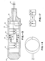
- the probe comprises a housing 40 in which are positioned four permanent magnets 26 and a magnetic connector 44 which, together with magnet pole pieces 42, provide an internal magnetic flux path within the probe.
- the flux leaves one pole piece, travels through the wall of the pipe, and re-enters the probe at the other pole piece.
- first coil 30 Mounted directly to the outer surface of connector 44 is the first coil 30, while the second coil 32 is mounted on the connector 44 by means of a spacer 45 whereby the two coils 30, 32 are radially displaced.
- the radial displacement of the two coils has proved to be advantageous in identifying both the location of defects and the magnitude of the defects.
- the Hall-effect sensor 38 is mounted between one pole piece 42 and the housing 40 of the probe for sensing flux lines between the pole piece and the tube undergoing inspection.
- One end of the probe is sealed by a plug 46 while the other end of the probe receives a plug 48 having an internal opening through which the electrical connectors 50 to the Hall-effect device and coils pass.
- Cord 14 (not shown) extends outwardly from the plug 48.
- the turns of the two coils 30 and 32 are configured to sense radially oriented flux. This is illustrated in one turn of a coil in the perspective view of Figure 4. Leads 52, 54 are interconnected to the turn, and it will be noted that the turn is annularly shaped for positioning on the connector 44 or the support 45 affixed to the cylindrical connector 44.
- the use of the two radially displaced coils has proved to be particularly advantageous in identifying the location and magnitude of defects such as pits and cracks.
- Figure 5A shows a section view of a length of test pipe 62 having defects A-H located therein. The diameter-to-width ratio of the defects, and the depths of the defects, are noted in Figure 5A.
- Figure 5B illustrates a strip chart print-out of the signal generated by one of the two radially offset coils as the test probe is passed through the test pipe in proximity to the defects.
- Each coil provides a flux leakage signal response for the calibration tube having spikes positioned in time to correspond with the location of the defects and with the magnitudes of the signal spikes corresponding to the magnitudes of the defects, and each coild is separately connected with a channel of the electronic amplifier.
- a difference in amplitudes of the two signals arises from the radially offset positions of the coils and the response characteristic of each coil. By comparison of signal amplitudes from both channels, defect depth and point of origin can be determined.
- the embodiment of the probe illustrated in Figure 3 is particularly advantageous in inspecting pipes and tubing having relatively thin walls.
- the magnetic circuit illustrated in Figure 7 is preferred.
- Like elements in Figures 3 and 7 have the same reference numerals.
- the primary difference in the circuit is the bevelled or tapered end portions of the soft steel connector 44 to facilitate the transfer of flux between the magnets and the connector 44.
- the magnetic flux leakage probe employing a plurality of radially offset flux leakage coils and preferably with a Hall-effect sensor has proved to be particularly useful in sensing defects in pipes and tubing of ferritic alloys and carbon steel material.
Landscapes
- Chemical & Material Sciences (AREA)
- Chemical Kinetics & Catalysis (AREA)
- Electrochemistry (AREA)
- Physics & Mathematics (AREA)
- Health & Medical Sciences (AREA)
- Life Sciences & Earth Sciences (AREA)
- Analytical Chemistry (AREA)
- Biochemistry (AREA)
- General Health & Medical Sciences (AREA)
- General Physics & Mathematics (AREA)
- Immunology (AREA)
- Pathology (AREA)
- Investigating Or Analyzing Materials By The Use Of Magnetic Means (AREA)
Applications Claiming Priority (2)
| Application Number | Priority Date | Filing Date | Title |
|---|---|---|---|
| US06/927,616 US4789827A (en) | 1986-10-31 | 1986-10-31 | Magnetic flux leakage probe with radially offset coils for use in nondestructive testing of pipes and tubes |
| US927616 | 1986-10-31 |
Publications (3)
| Publication Number | Publication Date |
|---|---|
| EP0266103A2 true EP0266103A2 (de) | 1988-05-04 |
| EP0266103A3 EP0266103A3 (en) | 1989-11-08 |
| EP0266103B1 EP0266103B1 (de) | 1994-05-18 |
Family
ID=25454996
Family Applications (1)
| Application Number | Title | Priority Date | Filing Date |
|---|---|---|---|
| EP87309183A Expired - Lifetime EP0266103B1 (de) | 1986-10-31 | 1987-10-16 | Magnetischer Streuflussfühler zur zerstörungsfreien Prüfung |
Country Status (8)
| Country | Link |
|---|---|
| US (1) | US4789827A (de) |
| EP (1) | EP0266103B1 (de) |
| JP (1) | JPH0664012B2 (de) |
| AT (1) | ATE105935T1 (de) |
| AU (1) | AU595748B2 (de) |
| CA (1) | CA1277710C (de) |
| DE (1) | DE3789848T2 (de) |
| ES (1) | ES2051747T3 (de) |
Cited By (5)
| Publication number | Priority date | Publication date | Assignee | Title |
|---|---|---|---|---|
| WO1995030895A1 (en) * | 1994-05-10 | 1995-11-16 | Gas Research Institute | Apparatus and method for detecting anomalies in ferrous pipe structures |
| RU2176317C1 (ru) * | 2000-03-13 | 2001-11-27 | Открытое акционерное общество Научно-производственное предприятие Научно-исследовательский и проектно-конструкторский институт геофизических исследований геологоразведочных скважин | Способ электромагнитной дефектоскопии стальных труб в скважинах |
| RU2338878C2 (ru) * | 2002-10-18 | 2008-11-20 | Шлюмбергер Текнолоджи Бв | Способ измерения магнитного поля в зоне обсадной трубы, опущенной в скважину, и способ уменьшения его затухания (варианты) |
| US11199592B2 (en) | 2017-05-19 | 2021-12-14 | Infrastructure Preservation Corporation | Robotic magnetic flux leakage inspection system for external post-tensioned tendons of segmental bridges and roadways |
| US11796506B2 (en) | 2019-02-08 | 2023-10-24 | Ipc Tfic, Llc | Robotic magnetic flux leakage inspection system for cable stays and related methods |
Families Citing this family (37)
| Publication number | Priority date | Publication date | Assignee | Title |
|---|---|---|---|---|
| JPS59126415U (ja) * | 1983-02-14 | 1984-08-25 | 日立電線株式会社 | 通信用ケ−ブル |
| US4945306A (en) * | 1988-10-25 | 1990-07-31 | Atlantic Richfield | Coil and Hall device circuit for sensing magnetic fields |
| GB2255184B (en) * | 1991-04-22 | 1995-08-16 | Tokyo Gas Co Ltd | Flaw detector for metal material |
| US5293117A (en) * | 1992-05-14 | 1994-03-08 | Western Atlas International, Inc. | Magnetic flaw detector for use with ferromagnetic small diameter tubular goods using a second magnetic field to confine a first magnetic field |
| US5475305A (en) * | 1993-02-18 | 1995-12-12 | Iowa State University Research Foundation, Inc. | Magnetic inspection probe for measurement of magnetic anisotropy |
| US5565633A (en) * | 1993-07-30 | 1996-10-15 | Wernicke; Timothy K. | Spiral tractor apparatus and method |
| US5454276A (en) * | 1993-07-30 | 1995-10-03 | Wernicke; Timothy K. | Multi-directional magnetic flux pipe inspection apparatus and method |
| FR2731498B1 (fr) * | 1995-03-08 | 1997-06-06 | Framatome Sa | Procede de reparation par chemisage electrolytique d'un tube tel qu'un tube de generateur de vapeur |
| US5864232A (en) * | 1996-08-22 | 1999-01-26 | Pipetronix, Ltd. | Magnetic flux pipe inspection apparatus for analyzing anomalies in a pipeline wall |
| FR2758393B1 (fr) * | 1997-01-10 | 1999-10-15 | Commissariat Energie Atomique | Sonde a courants de foucault |
| KR100358227B1 (ko) * | 2000-03-14 | 2002-10-25 | 이곤철 | 봉강의 결함탐상용 센서 및 그 제조방법 |
| KR100487737B1 (ko) | 2000-07-12 | 2005-05-03 | 제이에프이 스틸 가부시키가이샤 | 누설자속 탐상법 및 그 것을 이용한 열연강판의 제조방법 |
| GB0112983D0 (en) * | 2001-05-30 | 2001-07-18 | Advanced Eng Solutions Ltd | Pipe condition detecting apparatus |
| US7218102B2 (en) * | 2004-10-07 | 2007-05-15 | Battelle Memorial Institute | Pipeline inspection apparatus and method |
| US7595636B2 (en) * | 2005-03-11 | 2009-09-29 | Baker Hughes Incorporated | Apparatus and method of using accelerometer measurements for casing evaluation |
| US7804295B2 (en) * | 2005-04-28 | 2010-09-28 | Randel Brandstrom | Apparatus and method for detection of defects using flux leakage techniques |
| KR100696991B1 (ko) * | 2006-01-25 | 2007-03-20 | 한국원자력연구소 | 투자율 측정법을 이용하여 증기발생기 전열관의 와전류를탐상하는 장치 및 방법 |
| FR2900193B1 (fr) | 2006-04-21 | 2008-06-20 | Jean Pierre Martin | Procede et dispositif permettant de determiner l'existence et l'emplacement de forces de contraintes sur une tige |
| PL2100072T3 (pl) * | 2006-12-21 | 2019-07-31 | Athena Industrial Technologies Inc. | Przyrząd i sposób kontroli liniowej struktury |
| FR2914007B1 (fr) * | 2007-03-20 | 2009-05-29 | Geo Energy Sa | Sonde d'analyse d'un assemblage de tiges ou tubes |
| GB2460484B (en) * | 2007-11-16 | 2011-03-23 | Advanced Eng Solutions Ltd | Pipeline condition detecting method and apparatus |
| DE102009010453A1 (de) * | 2009-02-26 | 2010-09-09 | V&M Deutschland Gmbh | Vorrichtung zur zerstörungsfreien Prüfung von Rohren |
| US8319494B2 (en) * | 2009-06-26 | 2012-11-27 | Tdw Delaware Inc. | Pipeline inspection tool with double spiral EMAT sensor array |
| EP2612105A1 (de) * | 2010-10-14 | 2013-07-10 | Halliburton Energy Services, Inc. | Verfahren zur messung der stärke von remote-feld-eddyströmen in einer konfiguration mit mehreren röhren |
| GB201105193D0 (en) * | 2011-03-29 | 2011-05-11 | Silverwing Uk Ltd | Methods and apparatus for the inspection of plates and pipe walls |
| JP5851783B2 (ja) | 2011-09-27 | 2016-02-03 | 三菱重工業株式会社 | 渦電流探傷用プローブ |
| US8734024B2 (en) * | 2011-11-28 | 2014-05-27 | Corning Cable Systems Llc | Optical couplings having a coded magnetic array, and connector assemblies and electronic devices having the same |
| US9354350B2 (en) * | 2012-05-23 | 2016-05-31 | Schlumberger Technology Corporation | Magnetic field sensing tool with magnetic flux concentrating blocks |
| US9678041B2 (en) | 2014-07-24 | 2017-06-13 | City of Tallahassee | Non-destructive real-time magnetic flux leakage imaging system and method |
| US10168300B2 (en) * | 2014-08-28 | 2019-01-01 | Compagnie Generale Des Etablissements Michelin | Magnetic flux sensor quality indicator apparatus and method |
| CN104677981A (zh) * | 2015-01-17 | 2015-06-03 | 中国人民解放军装甲兵工程学院 | 一种多通道三维弱磁检测仪 |
| JP6579840B2 (ja) * | 2015-07-16 | 2019-09-25 | 住友化学株式会社 | 欠陥測定方法、欠陥測定装置、および検査プローブ |
| JP6514592B2 (ja) * | 2015-07-16 | 2019-05-15 | 住友化学株式会社 | 欠陥測定方法、欠陥測定装置および検査プローブ |
| US11009484B1 (en) | 2016-03-11 | 2021-05-18 | The University Of Tulsa | Velocity independent two-component magnetic flux leakage detective system |
| CN108375628B (zh) * | 2016-09-18 | 2022-07-26 | 中国石油大学(华东) | 一种周向电磁场管道内壁裂纹检测系统及定量评估方法 |
| US10465509B2 (en) | 2016-10-12 | 2019-11-05 | Baker Hughes, A Ge Company, Llc | Collocated multitone acoustic beam and electromagnetic flux leakage evaluation downhole |
| JP6978913B2 (ja) * | 2017-12-01 | 2021-12-08 | 住友化学株式会社 | 欠陥測定装置、欠陥測定方法および検査プローブ |
Family Cites Families (22)
| Publication number | Priority date | Publication date | Assignee | Title |
|---|---|---|---|---|
| US2992390A (en) * | 1956-06-18 | 1961-07-11 | Continental Oil Co | Method and apparatus for electrical testing of pipe |
| US3060377A (en) * | 1958-12-08 | 1962-10-23 | Shell Oil Co | Pipe inspection device |
| GB1032343A (en) * | 1961-09-07 | 1966-06-08 | Coal Industry Patents Ltd | Method and apparatus for detecting flaws in wire ropes |
| US3284701A (en) * | 1962-09-28 | 1966-11-08 | Camco Inc | Magnetic testing apparatus for measuring internal diameter and surface variations in wall casing |
| US3449662A (en) * | 1963-10-16 | 1969-06-10 | American Mach & Foundry | Magnetic inspection method and apparatus using resilient magnetizing means and resilient sensors |
| US3443211A (en) * | 1965-04-01 | 1969-05-06 | American Mach & Foundry | Magnetometer inspection apparatus for ferromagnetic objects |
| US3535624A (en) * | 1967-06-13 | 1970-10-20 | American Mach & Foundry | Apparatus for inspecting the inside and outside of a tubular member continuously moving in one direction |
| US3532969A (en) * | 1968-02-20 | 1970-10-06 | Nat Lead Co | Method for magnetically measuring wall thickness of metal pipes and plate structures |
| US3597678A (en) * | 1968-12-24 | 1971-08-03 | Williams Brothers Co | Apparatus for sensing thickness variations, discontinuities, and the like in elongated steel structures by measuring variations in magnetic properties utilizing a flux gate |
| US3899734A (en) * | 1973-05-14 | 1975-08-12 | Vetco Offshore Ind Inc | Magnetic flux leakage inspection method and apparatus including magnetic diodes |
| US3906358A (en) * | 1973-11-12 | 1975-09-16 | Combustion Eng | Probe train including a flaw detector and a radiation responsive recording means with alignment means having a natural curved cast |
| US3967194A (en) * | 1974-03-15 | 1976-06-29 | Vetco Offshore Industries | Method for flaw location in a magnetizable pipeline by use of magnetic markers positioned outside of said pipeline |
| US3949292A (en) * | 1974-03-15 | 1976-04-06 | Vetco Offshore Industries, Inc. | Pipeline inspection device with pivotal support structure |
| US3940689A (en) * | 1974-05-14 | 1976-02-24 | Schlumberger Technology Corporation | Combined eddy current and leakage field detector for well bore piping using a unique magnetizer core structure |
| US4088946A (en) * | 1975-07-28 | 1978-05-09 | Westinghouse Electric Corp. | Magnetic bridge transducer formed with permanent magnets and a hall effect sensor for identifying the presence and location of ferromagnetic discontinuities within or on a tubular specimen |
| US4188577A (en) * | 1975-12-11 | 1980-02-12 | Magnetic Analysis Corporation | Pulse eddy current testing apparatus for magnetic materials, particularly tubes |
| GB1567166A (en) * | 1976-12-16 | 1980-05-14 | British Gas Corp | Apparatus and method for the non-destructive testing of ferromagnetic material |
| GB1586581A (en) * | 1977-01-26 | 1981-03-18 | British Gas Corp | Pipeline inspection equipment |
| JPS55101044A (en) * | 1979-01-29 | 1980-08-01 | Denshi Jiki Kogyo Kk | Flaw detector |
| GB2044459B (en) * | 1979-03-16 | 1983-10-26 | British Gas Corp | Velocity correction arrangement for non-destructive testing apparatus |
| GB2086051B (en) * | 1980-10-17 | 1984-07-25 | British Gas Corp | Pipeline inspection vehicle |
| JPS59217160A (ja) * | 1983-05-25 | 1984-12-07 | Hitachi Ltd | 渦電流探傷プロ−ブ |
-
1986
- 1986-10-31 US US06/927,616 patent/US4789827A/en not_active Expired - Fee Related
-
1987
- 1987-10-16 DE DE3789848T patent/DE3789848T2/de not_active Expired - Fee Related
- 1987-10-16 ES ES87309183T patent/ES2051747T3/es not_active Expired - Lifetime
- 1987-10-16 EP EP87309183A patent/EP0266103B1/de not_active Expired - Lifetime
- 1987-10-16 AT AT87309183T patent/ATE105935T1/de not_active IP Right Cessation
- 1987-10-23 JP JP62268025A patent/JPH0664012B2/ja not_active Expired - Lifetime
- 1987-10-30 AU AU80521/87A patent/AU595748B2/en not_active Ceased
- 1987-10-30 CA CA000550664A patent/CA1277710C/en not_active Expired - Lifetime
Cited By (6)
| Publication number | Priority date | Publication date | Assignee | Title |
|---|---|---|---|---|
| WO1995030895A1 (en) * | 1994-05-10 | 1995-11-16 | Gas Research Institute | Apparatus and method for detecting anomalies in ferrous pipe structures |
| US5537035A (en) * | 1994-05-10 | 1996-07-16 | Gas Research Institute | Apparatus and method for detecting anomalies in ferrous pipe structures |
| RU2176317C1 (ru) * | 2000-03-13 | 2001-11-27 | Открытое акционерное общество Научно-производственное предприятие Научно-исследовательский и проектно-конструкторский институт геофизических исследований геологоразведочных скважин | Способ электромагнитной дефектоскопии стальных труб в скважинах |
| RU2338878C2 (ru) * | 2002-10-18 | 2008-11-20 | Шлюмбергер Текнолоджи Бв | Способ измерения магнитного поля в зоне обсадной трубы, опущенной в скважину, и способ уменьшения его затухания (варианты) |
| US11199592B2 (en) | 2017-05-19 | 2021-12-14 | Infrastructure Preservation Corporation | Robotic magnetic flux leakage inspection system for external post-tensioned tendons of segmental bridges and roadways |
| US11796506B2 (en) | 2019-02-08 | 2023-10-24 | Ipc Tfic, Llc | Robotic magnetic flux leakage inspection system for cable stays and related methods |
Also Published As
| Publication number | Publication date |
|---|---|
| JPH0664012B2 (ja) | 1994-08-22 |
| DE3789848T2 (de) | 1994-09-01 |
| US4789827A (en) | 1988-12-06 |
| CA1277710C (en) | 1990-12-11 |
| DE3789848D1 (de) | 1994-06-23 |
| AU595748B2 (en) | 1990-04-05 |
| EP0266103B1 (de) | 1994-05-18 |
| ES2051747T3 (es) | 1994-07-01 |
| EP0266103A3 (en) | 1989-11-08 |
| JPS63133054A (ja) | 1988-06-04 |
| ATE105935T1 (de) | 1994-06-15 |
| AU8052187A (en) | 1988-05-05 |
Similar Documents
| Publication | Publication Date | Title |
|---|---|---|
| US4789827A (en) | Magnetic flux leakage probe with radially offset coils for use in nondestructive testing of pipes and tubes | |
| US4107605A (en) | Eddy current flaw detector utilizing plural sets of four planar coils, with the plural sets disposed in a common bridge | |
| US5414353A (en) | Method and device for nondestructively inspecting elongated objects for structural defects using longitudinally arranged magnet means and sensor means disposed immediately downstream therefrom | |
| US5914596A (en) | Coiled tubing inspection system | |
| US4295092A (en) | Apparatus for and method of detecting and measuring corrosion damage in pipe | |
| EP0594844B1 (de) | Magnetisches rissprüfgerät für ferromagnetische gegenstände | |
| US4659991A (en) | Method and apparatus for magnetically inspecting elongated objects for structural defects | |
| US7038445B2 (en) | Method, system and apparatus for ferromagnetic wall monitoring | |
| US6847207B1 (en) | ID-OD discrimination sensor concept for a magnetic flux leakage inspection tool | |
| US4855676A (en) | Ferromagnetic eddy current probe having transmit and receive coil assemblies | |
| US5049817A (en) | Eddy current probe, incorporating multi-bracelets of different pancake coil diameters, for detecting internal defects in ferromagnetic tubes | |
| EP0543952B1 (de) | Untersuchungsverfahren mittels induktion transienter ströme mit beweglichen sensoren | |
| JPS61223549A (ja) | パイプラインの孔食検出装置 | |
| US4806863A (en) | Eddy current apparatus including cylindrical coil with flux concentrator for high resolution detection of flaws in conductive objects | |
| US5117182A (en) | Ferromagnetic eddy current probe having multiple levels of magnetization | |
| CA1166696A (en) | Non-destructive testing of ferromagnetic articles | |
| CA2268446A1 (en) | Coiled tubing inspection system | |
| AU768407B2 (en) | Method and device for measuring in situ the distance between two specific elements in a tubular pipe | |
| RU2191365C2 (ru) | Локатор перфорационных отверстий и соединительных муфт обсадных ферромагнитных труб | |
| JPH03118465A (ja) | 管内欠陥検出装置 | |
| JPH08278289A (ja) | 強磁性管の探傷装置および探傷方法 | |
| CA1293024C (en) | Ferromagnetic eddy current probe | |
| CN113237946A (zh) | 一种轴承滚针阵列式漏磁检测装置 | |
| MXPA99003556A (en) | Coiled tubing inspection system | |
| JPH02269958A (ja) | 探傷用プローブ |
Legal Events
| Date | Code | Title | Description |
|---|---|---|---|
| PUAI | Public reference made under article 153(3) epc to a published international application that has entered the european phase |
Free format text: ORIGINAL CODE: 0009012 |
|
| AK | Designated contracting states |
Kind code of ref document: A2 Designated state(s): AT BE CH DE ES FR GB GR IT LI LU NL SE |
|
| PUAL | Search report despatched |
Free format text: ORIGINAL CODE: 0009013 |
|
| AK | Designated contracting states |
Kind code of ref document: A3 Designated state(s): AT BE CH DE ES FR GB GR IT LI LU NL SE |
|
| RHK1 | Main classification (correction) |
Ipc: G01N 27/82 |
|
| 17P | Request for examination filed |
Effective date: 19900508 |
|
| 17Q | First examination report despatched |
Effective date: 19911205 |
|
| GRAA | (expected) grant |
Free format text: ORIGINAL CODE: 0009210 |
|
| AK | Designated contracting states |
Kind code of ref document: B1 Designated state(s): AT BE CH DE ES FR GB GR IT LI LU NL SE |
|
| REF | Corresponds to: |
Ref document number: 105935 Country of ref document: AT Date of ref document: 19940615 Kind code of ref document: T |
|
| ITF | It: translation for a ep patent filed | ||
| REF | Corresponds to: |
Ref document number: 3789848 Country of ref document: DE Date of ref document: 19940623 |
|
| REG | Reference to a national code |
Ref country code: ES Ref legal event code: FG2A Ref document number: 2051747 Country of ref document: ES Kind code of ref document: T3 |
|
| ET | Fr: translation filed | ||
| REG | Reference to a national code |
Ref country code: GR Ref legal event code: FG4A Free format text: 3012261 |
|
| PGFP | Annual fee paid to national office [announced via postgrant information from national office to epo] |
Ref country code: LU Payment date: 19940901 Year of fee payment: 8 |
|
| PGFP | Annual fee paid to national office [announced via postgrant information from national office to epo] |
Ref country code: FR Payment date: 19940916 Year of fee payment: 8 Ref country code: DE Payment date: 19940916 Year of fee payment: 8 Ref country code: CH Payment date: 19940916 Year of fee payment: 8 |
|
| PGFP | Annual fee paid to national office [announced via postgrant information from national office to epo] |
Ref country code: SE Payment date: 19940920 Year of fee payment: 8 Ref country code: AT Payment date: 19940920 Year of fee payment: 8 |
|
| PGFP | Annual fee paid to national office [announced via postgrant information from national office to epo] |
Ref country code: GB Payment date: 19940927 Year of fee payment: 8 |
|
| PGFP | Annual fee paid to national office [announced via postgrant information from national office to epo] |
Ref country code: GR Payment date: 19940928 Year of fee payment: 8 |
|
| PGFP | Annual fee paid to national office [announced via postgrant information from national office to epo] |
Ref country code: BE Payment date: 19940929 Year of fee payment: 8 |
|
| PGFP | Annual fee paid to national office [announced via postgrant information from national office to epo] |
Ref country code: ES Payment date: 19941013 Year of fee payment: 8 |
|
| PGFP | Annual fee paid to national office [announced via postgrant information from national office to epo] |
Ref country code: NL Payment date: 19941031 Year of fee payment: 8 |
|
| EAL | Se: european patent in force in sweden |
Ref document number: 87309183.9 |
|
| PLBE | No opposition filed within time limit |
Free format text: ORIGINAL CODE: 0009261 |
|
| STAA | Information on the status of an ep patent application or granted ep patent |
Free format text: STATUS: NO OPPOSITION FILED WITHIN TIME LIMIT |
|
| 26N | No opposition filed | ||
| PG25 | Lapsed in a contracting state [announced via postgrant information from national office to epo] |
Ref country code: LU Free format text: LAPSE BECAUSE OF NON-PAYMENT OF DUE FEES Effective date: 19951016 Ref country code: GB Effective date: 19951016 Ref country code: AT Effective date: 19951016 |
|
| PG25 | Lapsed in a contracting state [announced via postgrant information from national office to epo] |
Ref country code: SE Effective date: 19951017 Ref country code: ES Free format text: LAPSE BECAUSE OF EXPIRATION OF PROTECTION Effective date: 19951017 |
|
| PG25 | Lapsed in a contracting state [announced via postgrant information from national office to epo] |
Ref country code: LI Effective date: 19951031 Ref country code: CH Effective date: 19951031 Ref country code: BE Effective date: 19951031 |
|
| BERE | Be: lapsed |
Owner name: ELECTRIC POWER RESEARCH INSTITUTE INC. Effective date: 19951031 |
|
| PG25 | Lapsed in a contracting state [announced via postgrant information from national office to epo] |
Ref country code: GR Free format text: THE PATENT HAS BEEN ANNULLED BY A DECISION OF A NATIONAL AUTHORITY Effective date: 19960430 |
|
| PG25 | Lapsed in a contracting state [announced via postgrant information from national office to epo] |
Ref country code: NL Effective date: 19960501 |
|
| GBPC | Gb: european patent ceased through non-payment of renewal fee |
Effective date: 19951016 |
|
| REG | Reference to a national code |
Ref country code: CH Ref legal event code: PL |
|
| PG25 | Lapsed in a contracting state [announced via postgrant information from national office to epo] |
Ref country code: FR Effective date: 19960628 |
|
| REG | Reference to a national code |
Ref country code: GR Ref legal event code: MM2A Free format text: 3012261 |
|
| EUG | Se: european patent has lapsed |
Ref document number: 87309183.9 |
|
| PG25 | Lapsed in a contracting state [announced via postgrant information from national office to epo] |
Ref country code: DE Effective date: 19960702 |
|
| NLV4 | Nl: lapsed or anulled due to non-payment of the annual fee |
Effective date: 19960501 |
|
| REG | Reference to a national code |
Ref country code: FR Ref legal event code: ST |
|
| REG | Reference to a national code |
Ref country code: ES Ref legal event code: FD2A Effective date: 19990601 |
|
| PG25 | Lapsed in a contracting state [announced via postgrant information from national office to epo] |
Ref country code: IT Free format text: LAPSE BECAUSE OF NON-PAYMENT OF DUE FEES Effective date: 20051016 |