EP0266324A2 - Méthode et dispositif pour connecter un corps porte-outil avec une tête porte-outil - Google Patents
Méthode et dispositif pour connecter un corps porte-outil avec une tête porte-outil Download PDFInfo
- Publication number
- EP0266324A2 EP0266324A2 EP87850305A EP87850305A EP0266324A2 EP 0266324 A2 EP0266324 A2 EP 0266324A2 EP 87850305 A EP87850305 A EP 87850305A EP 87850305 A EP87850305 A EP 87850305A EP 0266324 A2 EP0266324 A2 EP 0266324A2
- Authority
- EP
- European Patent Office
- Prior art keywords
- clamping jaws
- draw bar
- plug
- tool head
- head
- Prior art date
- Legal status (The legal status is an assumption and is not a legal conclusion. Google has not performed a legal analysis and makes no representation as to the accuracy of the status listed.)
- Granted
Links
- 238000000034 method Methods 0.000 title claims abstract description 7
- 238000006073 displacement reaction Methods 0.000 claims abstract description 10
- 230000003213 activating effect Effects 0.000 claims 1
- 230000002349 favourable effect Effects 0.000 description 2
- 238000003801 milling Methods 0.000 description 2
- 230000007704 transition Effects 0.000 description 2
- 238000004873 anchoring Methods 0.000 description 1
- 230000006835 compression Effects 0.000 description 1
- 238000007906 compression Methods 0.000 description 1
Images

Classifications
-
- B—PERFORMING OPERATIONS; TRANSPORTING
- B23—MACHINE TOOLS; METAL-WORKING NOT OTHERWISE PROVIDED FOR
- B23B—TURNING; BORING
- B23B29/00—Holders for non-rotary cutting tools; Boring bars or boring heads; Accessories for tool holders
- B23B29/04—Tool holders for a single cutting tool
- B23B29/046—Tool holders for a single cutting tool with an intermediary toolholder
-
- Y—GENERAL TAGGING OF NEW TECHNOLOGICAL DEVELOPMENTS; GENERAL TAGGING OF CROSS-SECTIONAL TECHNOLOGIES SPANNING OVER SEVERAL SECTIONS OF THE IPC; TECHNICAL SUBJECTS COVERED BY FORMER USPC CROSS-REFERENCE ART COLLECTIONS [XRACs] AND DIGESTS
- Y10—TECHNICAL SUBJECTS COVERED BY FORMER USPC
- Y10T—TECHNICAL SUBJECTS COVERED BY FORMER US CLASSIFICATION
- Y10T82/00—Turning
- Y10T82/25—Lathe
- Y10T82/2585—Tool rest
-
- Y—GENERAL TAGGING OF NEW TECHNOLOGICAL DEVELOPMENTS; GENERAL TAGGING OF CROSS-SECTIONAL TECHNOLOGIES SPANNING OVER SEVERAL SECTIONS OF THE IPC; TECHNICAL SUBJECTS COVERED BY FORMER USPC CROSS-REFERENCE ART COLLECTIONS [XRACs] AND DIGESTS
- Y10—TECHNICAL SUBJECTS COVERED BY FORMER USPC
- Y10T—TECHNICAL SUBJECTS COVERED BY FORMER US CLASSIFICATION
- Y10T82/00—Turning
- Y10T82/25—Lathe
- Y10T82/2585—Tool rest
- Y10T82/2587—Turret type holder [e.g., multiple tools, etc.]
-
- Y—GENERAL TAGGING OF NEW TECHNOLOGICAL DEVELOPMENTS; GENERAL TAGGING OF CROSS-SECTIONAL TECHNOLOGIES SPANNING OVER SEVERAL SECTIONS OF THE IPC; TECHNICAL SUBJECTS COVERED BY FORMER USPC CROSS-REFERENCE ART COLLECTIONS [XRACs] AND DIGESTS
- Y10—TECHNICAL SUBJECTS COVERED BY FORMER USPC
- Y10T—TECHNICAL SUBJECTS COVERED BY FORMER US CLASSIFICATION
- Y10T82/00—Turning
- Y10T82/25—Lathe
- Y10T82/2585—Tool rest
- Y10T82/2589—Quick release tool or holder clamp
Definitions
- This invention refers to a method and a device for connecting a holder body with a tool head, a plug of the holder body being inserted in a recess of the tool head.
- the device according to the invention also has a draw bar provided in connection with the plug, said draw bar having a head and a portion tapering from the head, and means for displacing the draw bar in its longitudinal direction relative to the holder body.
- the device according to US-A-4 406 195 also causes great friction losses between the draw bar, the clamping pins and the tool head.
- the aim of the present invention is to disclose a method and a device of the type mentioned above, the clamping force mainly having axial direction and the friction losses between cooperating force transmitting means are eliminated.
- the aim of the present invention is realized by a method and a device that have been given the characteristics of the appending claims.
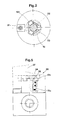
- the device according to the invention as disclosed in Figs 1-5 comprise a holder body 10, that has a plug 11
- Three clamping jaws 13 and an intermediate portion 14a of a draw bar 14 are received in the recess 12.
- the longitudinal centre axis for the plug 11 and the draw bar 14 is designed by reference numeral 15.
- a boring 16 continues, said boring having reduced diameter relative to the recess 12 in a direction from the plug 11.
- the boring 16 emerges in a space 17 in the holder body 10.
- An eccentric mechanism 18 is provided in said space 17 and connected to the draw bar 14, e.g. by means of a thread connection 19. When the eccentric mechanism 18 is activated the draw bar 14 is given a displacement towards or away from the space 17.
- the clamping jaws 13 are L-shaped, the stem 13a of the L extends down into the recess 12 along the draw bar 14 while the shank 13b of the L extends radially away from the draw bar in a direction transverse to the longitudinal direction of the stem 13a.
- both the stem 13a and the shank 13b have a shape that tapers towards their joining point, seen in a plane through a clamping jaw 13 and the centre axis 15 of the plug 11.
- slots 20 are provided, said slots extend from the free end of the plug 11 and in axial direction of the plug 11 a limited distance.
- the width of the slots 20 in the tangential direction of the plug 11 is somewhat bigger than the width of the shank 13b of the clamping jaws 13 in order to make it possible to displace them out through the slots 20.
- the stems 13a of the clamping jaws 13 have on their side that is directed from the intermediate portion 14a of the draw bar 14 grooves 21 that have an extension transverse to the longitudinal direction of the stems 13a.
- two grooves 21 are arranged on each stem 13a.
- a resilient O-ring 22 is received in associated grooves 21 of the stems 13a. This means that in the disclosed embodiment each O-ring 22 passes through three grooves 21.
- the O-rings 22 are given such a diameter that they are only slightly pre-stressed in the position of the clamping jaws 13 according to Fig 1.
- the draw bar 14 has a head 24 at its end that is directed from the plug 11.
- a tool head 26 is drawn with dotted lines.
- This tool head supports in the disclosed embodiment a cutting insert 27.
- other types of tool heads e.g. a milling cutter, can be used.
- the tool head 26 has an axially extending through hole 28 that has a diameter that corresponds to the diameter of the plug 11, i.e. the hole 28 has a so-called slide fit relative to the plug 11.
- the hole 28 has a portion 29 with a greater diameter than the rest of the hole 28.
- a step 30 is provided, said step having an extension in radial direction relative to the centre axis of the hole 28, said axis coincides with the centre axis 15 of the plug 11 and the draw bar 14.
- the draw bar 14 is displaced in direction towards the space 17. This displacement is realized by means of the eccentric mechanism 18.
- the force that presses the shanks 13b against the step 30 is contolled by means of the eccentric mechanism 18 and can of course be varied according to requirements.
- the stems 13a and the shanks 13b of the clamping jaws 13 has a shape that tapers towards their joining point.
- the tapering shape means that the radially outmost portion of the shanks 13b will contact the step 30 when the clamping jaws are displaced axially. This is favourable as a bigger distance in radial direction between the clamping jaws gives a more steady anchoring of the tool head 26. Also it is avoided that the wall of the hole 28 is damaged.
- the tool head 26 must not be provided with a through hole 28 but it is also possible to have a recess provided with a step.
- tool head is to be given a general interpretation and thus also incorporate milling heads, turning tools etc..
Landscapes
- Engineering & Computer Science (AREA)
- Mechanical Engineering (AREA)
- Gripping On Spindles (AREA)
- Cutting Tools, Boring Holders, And Turrets (AREA)
- Manufacturing Of Electrical Connectors (AREA)
- Automatic Assembly (AREA)
Applications Claiming Priority (2)
| Application Number | Priority Date | Filing Date | Title |
|---|---|---|---|
| SE8604671 | 1986-10-31 | ||
| SE8604671A SE454488B (sv) | 1986-10-31 | 1986-10-31 | Forfarande och anordning for att astadkomma hopkoppling av en hallarkropp med ett verktygshuvud |
Publications (3)
| Publication Number | Publication Date |
|---|---|
| EP0266324A2 true EP0266324A2 (fr) | 1988-05-04 |
| EP0266324A3 EP0266324A3 (en) | 1990-01-03 |
| EP0266324B1 EP0266324B1 (fr) | 1993-03-31 |
Family
ID=20366149
Family Applications (1)
| Application Number | Title | Priority Date | Filing Date |
|---|---|---|---|
| EP87850305A Expired - Lifetime EP0266324B1 (fr) | 1986-10-31 | 1987-10-13 | Méthode et dispositif pour connecter un corps porte-outil avec une tête porte-outil |
Country Status (5)
| Country | Link |
|---|---|
| US (1) | US4843929A (fr) |
| EP (1) | EP0266324B1 (fr) |
| JP (1) | JPS63162104A (fr) |
| DE (1) | DE3785144T2 (fr) |
| SE (1) | SE454488B (fr) |
Cited By (4)
| Publication number | Priority date | Publication date | Assignee | Title |
|---|---|---|---|---|
| WO1990009253A1 (fr) * | 1989-02-13 | 1990-08-23 | Gottlieb Gühring Kg | Accouplement pour la fixation amovible de pieces sur des parties de support correspondantes |
| WO1995027581A1 (fr) * | 1994-04-08 | 1995-10-19 | Kennametal Inc. | Appareil de saisie d'une queue de porte-outil |
| DE19818148A1 (de) * | 1998-04-23 | 1999-10-28 | Widia Gmbh | Spannvorrichtung |
| US6506220B2 (en) | 1998-09-30 | 2003-01-14 | Unilever Home & Personal Care Usa Division Of Conopco | Treatment for fabrics |
Families Citing this family (4)
| Publication number | Priority date | Publication date | Assignee | Title |
|---|---|---|---|---|
| SE468631B (sv) * | 1989-03-08 | 1993-02-22 | Sandvik Ab | Verktygskoppling med radiellt foerskjutbara laaselement samverkande med en dragstaang |
| US5452631A (en) * | 1994-04-08 | 1995-09-26 | Kennametal Inc. | Apparatus for holding a toolholder shank utilizing a rotatable cam to minimize kickback |
| US8151673B2 (en) * | 2009-09-23 | 2012-04-10 | Kennametal Inc. | Off-axis spring held clamping unit |
| CN103717333A (zh) * | 2011-08-02 | 2014-04-09 | 伊斯卡有限公司 | 模块化切削工具支架及其夹持机构 |
Family Cites Families (10)
| Publication number | Priority date | Publication date | Assignee | Title |
|---|---|---|---|---|
| US2942897A (en) * | 1957-12-10 | 1960-06-28 | Eon Corp | Fastening device |
| US3722363A (en) * | 1970-10-08 | 1973-03-27 | Moog Inc | Automatic tool changer |
| US3762271A (en) * | 1971-06-01 | 1973-10-02 | Ratier Sa Forest | Device for clamping a taper shank tool-holder in the nose of a rotary machine-tool spindle |
| US4226562A (en) * | 1977-09-16 | 1980-10-07 | Schmid-Kosta Kg | Toolholder |
| JPS55120943A (en) * | 1979-03-09 | 1980-09-17 | Brother Ind Ltd | Tool replacing device for machine tool |
| DE3007440A1 (de) * | 1980-02-28 | 1981-09-17 | Fried. Krupp Gmbh, 4300 Essen | Werkzeugeinrichtung mit wechselbarem werkzeugtraeger |
| DE3243948A1 (de) * | 1982-11-27 | 1984-07-05 | Gerhard 7142 Marbach Rall | Teilbares werkzeug fuer die spanabhebende bearbeitung |
| EP0101917B1 (fr) * | 1982-07-30 | 1986-05-28 | Gerhard Rall | Outil d'alésage |
| EP0193020B1 (fr) * | 1985-03-01 | 1990-11-28 | Fried. Krupp Gesellschaft mit beschränkter Haftung | Dispositif d'outillage avec tête interchangeable |
| US4604009A (en) * | 1985-07-12 | 1986-08-05 | Illinois Tool Works Inc. | Tool retention mechanism |
-
1986
- 1986-10-31 SE SE8604671A patent/SE454488B/sv not_active IP Right Cessation
-
1987
- 1987-10-13 DE DE8787850305T patent/DE3785144T2/de not_active Expired - Fee Related
- 1987-10-13 EP EP87850305A patent/EP0266324B1/fr not_active Expired - Lifetime
- 1987-10-30 JP JP62273609A patent/JPS63162104A/ja active Pending
- 1987-10-30 US US07/114,753 patent/US4843929A/en not_active Expired - Fee Related
Cited By (6)
| Publication number | Priority date | Publication date | Assignee | Title |
|---|---|---|---|---|
| WO1990009253A1 (fr) * | 1989-02-13 | 1990-08-23 | Gottlieb Gühring Kg | Accouplement pour la fixation amovible de pieces sur des parties de support correspondantes |
| US5150995A (en) * | 1989-02-13 | 1992-09-29 | Gottlieb Guhring Kg | Coupling for a detachable fixing of components at appropriate carrier members |
| WO1995027581A1 (fr) * | 1994-04-08 | 1995-10-19 | Kennametal Inc. | Appareil de saisie d'une queue de porte-outil |
| DE19818148A1 (de) * | 1998-04-23 | 1999-10-28 | Widia Gmbh | Spannvorrichtung |
| DE19818148B4 (de) * | 1998-04-23 | 2005-09-22 | Widia Gmbh | Spannvorrichtung |
| US6506220B2 (en) | 1998-09-30 | 2003-01-14 | Unilever Home & Personal Care Usa Division Of Conopco | Treatment for fabrics |
Also Published As
| Publication number | Publication date |
|---|---|
| DE3785144D1 (de) | 1993-05-06 |
| EP0266324B1 (fr) | 1993-03-31 |
| SE8604671D0 (sv) | 1986-10-31 |
| EP0266324A3 (en) | 1990-01-03 |
| SE454488B (sv) | 1988-05-09 |
| JPS63162104A (ja) | 1988-07-05 |
| DE3785144T2 (de) | 1993-07-15 |
| US4843929A (en) | 1989-07-04 |
Similar Documents
| Publication | Publication Date | Title |
|---|---|---|
| US4938640A (en) | Metal cutting tool | |
| US6109152A (en) | Cutting tool assembly | |
| DK167602B1 (da) | Vaerktoejssamling | |
| EP1328366B1 (fr) | Outil pivotant dont l'extremite libre d'enlevement de copeaux est pourvue d'une partie active remplacable | |
| US4292866A (en) | Toolholder with expansible shank | |
| US4726268A (en) | Clamping apparatus for holding a toolholder shank | |
| EP0239556A1 (fr) | Dispositif d'accouplement pour deux éléments | |
| EP1497063A1 (fr) | Outil de coupe et tete de coupe associee | |
| EP0202209A2 (fr) | Outil et pastille, de préférence pour le tournage | |
| KR840009236A (ko) | 급속 교환 공구척 시스템 | |
| EP0266324A2 (fr) | Méthode et dispositif pour connecter un corps porte-outil avec une tête porte-outil | |
| CN105377485A (zh) | 用于旋转工具的快速调换系统 | |
| US5915895A (en) | Drilling and chamfering tool | |
| RU2121906C1 (ru) | Цанговый патрон для инструмента с квадратным хвостовиком | |
| EP0668807B1 (fr) | Tige pour outil de fraisage, comportant des evidements destines a cooperer avec un mandrin | |
| JPH0248363B2 (fr) | ||
| JPH0372403B2 (fr) | ||
| CA2142447A1 (fr) | Dispositif de serrage pour broches de machines avec porte-outils | |
| EP0846516A1 (fr) | Porte-outil pour plaquette de coupe indexable | |
| KR20010023806A (ko) | 칩제거 가공용 공구 | |
| EP0137680B1 (fr) | Outil de coupe | |
| EP0684884B1 (fr) | Dispositif de fixation pour fraiseuses et machines similaires et adaptable a des dimensions de support differentes | |
| EP0247011A2 (fr) | Dispositif de fixation pour une plaquette de coupe blocable desmodromiquement | |
| US6739600B1 (en) | Expanding sleeve fixture | |
| US4884483A (en) | Device for locking a tool holder to a tool block |
Legal Events
| Date | Code | Title | Description |
|---|---|---|---|
| PUAI | Public reference made under article 153(3) epc to a published international application that has entered the european phase |
Free format text: ORIGINAL CODE: 0009012 |
|
| AK | Designated contracting states |
Kind code of ref document: A2 Designated state(s): DE FR GB IT SE |
|
| PUAL | Search report despatched |
Free format text: ORIGINAL CODE: 0009013 |
|
| AK | Designated contracting states |
Kind code of ref document: A3 Designated state(s): DE FR GB IT SE |
|
| 17P | Request for examination filed |
Effective date: 19900702 |
|
| 17Q | First examination report despatched |
Effective date: 19910710 |
|
| GRAA | (expected) grant |
Free format text: ORIGINAL CODE: 0009210 |
|
| ITF | It: translation for a ep patent filed | ||
| AK | Designated contracting states |
Kind code of ref document: B1 Designated state(s): DE FR GB IT SE |
|
| REF | Corresponds to: |
Ref document number: 3785144 Country of ref document: DE Date of ref document: 19930506 |
|
| ET | Fr: translation filed | ||
| PLBE | No opposition filed within time limit |
Free format text: ORIGINAL CODE: 0009261 |
|
| STAA | Information on the status of an ep patent application or granted ep patent |
Free format text: STATUS: NO OPPOSITION FILED WITHIN TIME LIMIT |
|
| 26N | No opposition filed | ||
| EAL | Se: european patent in force in sweden |
Ref document number: 87850305.1 |
|
| PGFP | Annual fee paid to national office [announced via postgrant information from national office to epo] |
Ref country code: SE Payment date: 19981006 Year of fee payment: 12 |
|
| PGFP | Annual fee paid to national office [announced via postgrant information from national office to epo] |
Ref country code: FR Payment date: 19981009 Year of fee payment: 12 |
|
| PGFP | Annual fee paid to national office [announced via postgrant information from national office to epo] |
Ref country code: GB Payment date: 19981016 Year of fee payment: 12 Ref country code: DE Payment date: 19981016 Year of fee payment: 12 |
|
| PG25 | Lapsed in a contracting state [announced via postgrant information from national office to epo] |
Ref country code: GB Free format text: LAPSE BECAUSE OF NON-PAYMENT OF DUE FEES Effective date: 19991013 |
|
| PG25 | Lapsed in a contracting state [announced via postgrant information from national office to epo] |
Ref country code: SE Free format text: THE PATENT HAS BEEN ANNULLED BY A DECISION OF A NATIONAL AUTHORITY Effective date: 19991030 |
|
| GBPC | Gb: european patent ceased through non-payment of renewal fee |
Effective date: 19991013 |
|
| EUG | Se: european patent has lapsed |
Ref document number: 87850305.1 |
|
| PG25 | Lapsed in a contracting state [announced via postgrant information from national office to epo] |
Ref country code: FR Free format text: LAPSE BECAUSE OF NON-PAYMENT OF DUE FEES Effective date: 20000630 |
|
| PG25 | Lapsed in a contracting state [announced via postgrant information from national office to epo] |
Ref country code: DE Free format text: LAPSE BECAUSE OF NON-PAYMENT OF DUE FEES Effective date: 20000801 |
|
| REG | Reference to a national code |
Ref country code: FR Ref legal event code: ST |
|
| PG25 | Lapsed in a contracting state [announced via postgrant information from national office to epo] |
Ref country code: IT Free format text: LAPSE BECAUSE OF NON-PAYMENT OF DUE FEES;WARNING: LAPSES OF ITALIAN PATENTS WITH EFFECTIVE DATE BEFORE 2007 MAY HAVE OCCURRED AT ANY TIME BEFORE 2007. THE CORRECT EFFECTIVE DATE MAY BE DIFFERENT FROM THE ONE RECORDED. Effective date: 20051013 |