EP0266380B1 - Vakuumtrockner für gegerbte häute mit mehreren arbeitstischen - Google Patents
Vakuumtrockner für gegerbte häute mit mehreren arbeitstischen Download PDFInfo
- Publication number
- EP0266380B1 EP0266380B1 EP87902466A EP87902466A EP0266380B1 EP 0266380 B1 EP0266380 B1 EP 0266380B1 EP 87902466 A EP87902466 A EP 87902466A EP 87902466 A EP87902466 A EP 87902466A EP 0266380 B1 EP0266380 B1 EP 0266380B1
- Authority
- EP
- European Patent Office
- Prior art keywords
- platforms
- drying machine
- cylinders
- machine according
- platform
- Prior art date
- Legal status (The legal status is an assumption and is not a legal conclusion. Google has not performed a legal analysis and makes no representation as to the accuracy of the status listed.)
- Expired
Links
Images



Classifications
-
- F—MECHANICAL ENGINEERING; LIGHTING; HEATING; WEAPONS; BLASTING
- F26—DRYING
- F26B—DRYING SOLID MATERIALS OR OBJECTS BY REMOVING LIQUID THEREFROM
- F26B9/00—Machines or apparatus for drying solid materials or objects at rest or with only local agitation; Domestic airing cupboards
- F26B9/04—Machines or apparatus for drying solid materials or objects at rest or with only local agitation; Domestic airing cupboards in presses or clamping devices
-
- C—CHEMISTRY; METALLURGY
- C14—SKINS; HIDES; PELTS; LEATHER
- C14B—MECHANICAL TREATMENT OR PROCESSING OF SKINS, HIDES OR LEATHER IN GENERAL; PELT-SHEARING MACHINES; INTESTINE-SPLITTING MACHINES
- C14B1/00—Manufacture of leather; Machines or devices therefor
- C14B1/58—Drying
-
- F—MECHANICAL ENGINEERING; LIGHTING; HEATING; WEAPONS; BLASTING
- F26—DRYING
- F26B—DRYING SOLID MATERIALS OR OBJECTS BY REMOVING LIQUID THEREFROM
- F26B5/00—Drying solid materials or objects by processes not involving the application of heat
- F26B5/04—Drying solid materials or objects by processes not involving the application of heat by evaporation or sublimation of moisture under reduced pressure, e.g. in a vacuum
- F26B5/045—Drying solid materials or objects by processes not involving the application of heat by evaporation or sublimation of moisture under reduced pressure, e.g. in a vacuum for drying thin, flat articles in a batch operation, e.g. leather, rugs, gels
Definitions
- the present invention relates to a vacuum drying machine for tanned skins, with multiple work surfaces.
- Vacuum drying machines are known for example from US-A-1 854 341 which comprise a plurality of vertically movable superimposed platforms, each of which defines a work surface with its upper face, the skin or skins to be dried being laid thereon.
- each platform is provided, on its lower face, with a cover, the perimetral edge of which can be brought into sealing contact against the underlying work surface; the cover and the underlying platform thus provide, when joined together, an evaporation chamber in which the skins being treated are enclosed.
- a cover is furthermore provided above all the platforms, and is also vertically movable or fixed to the framework of the machine, and cooperates with the work surface of the uppermost platform.
- the work surfaces are heated by appropriate heating means and a depression is provided inside the evaporation chambers by suitable suction means.
- each cylinder is provided with its liner fixed to the base of the framework and the upper end of its piston is fixed to a support which projects from the platform, supporting it from below.
- Such a system for moving the platforms is however not devoid of disadvantages, among which the main one is that, in order to achieve the required operating strokes, very long cylinders must be used, with accordingly extended liners, which entail large dimensions and are difficult to accommodate inside the machine. It is thus sometimes impossible to keep the operating positions of the various platforms at correct heights, and the overall height of the machine reaches very high values.
- the main aim of the present invention is to eliminate the disadvantages described above in known types of drying machines with multiple work surfaces, by devising a drying machine wherein the platforms are moved so that besides allowing to keep constant the height of the work surface on which one operates, with the consequent advantage of the elimination of any movable stand or other equivalent accessory, it is possible to contain both the work height and the overall height of the machine, without providing downwardly protruding elements.
- a particular object of the invention is to provide a system of movement wherein the coupling between the platforms and the framework of the machine makes the platforms furthermore subject to a self-centering action which makes them automatically assume the most appropriate position, adapting to any eventual irregularity in the guiding means, and being able to absorb without any disadvantage thermal variations produced e.g., by the variable heat status of the machine.
- Another important object is to provide a device for moving the platforms which is provided with a simplified structure, wherein the component elements can be assembled quickly and without requiring constructive complications and is furthermore designed so as to facilitate transport, installation and any subsequent intervention on the machine, such as e.g. maintenance or replacement of components.
- Not least object is to provide the drying machine with a system for moving the platforms which can be easily obtained starting from component elements commonly available on the market and which is furthermore competitive from an economic standpoint.
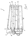
- a vacuum drying machine with multiple work surfaces for tanned skins comprises a framework which is provided laterally with a pair of vertical uprights 3, between which a plurality of platforms 4 extends, which platforms are stacked and arranged in horizontal planes, which are vertically movable, both independently and in mutual cooperation.
- Each platform 4 defines, with its upper face 5, a work surface on which the skin or skins to be dried are laid.
- the remaining platforms 4 are provided, applied to the lower face, with a cover 6, or with another equivalent element, provided with circumferential borders 7 capable of sealingly coupling to the work platform 5 of the underlying platform, defining a sealed evaporation chamber which operates in depression, wherein the skin or skins, which are being dried, are enclosed.
- An upper cover 8, suitable for cooperating with the work surface of the upper platform, indicated with the reference numeral 4b, is provide above all the platforms 4 and can be fixed, as in the example illustrated in Figures 1 to 3, supported by an upper framework 9 which connects the two uprights 3 to each other, or also vertically movable to follow the movements of the underlying platform 4b, as illustrated in Figure 9 related to a two-platform drying machine, indicated with the reference numeral 1a.
- Each platform 4 is provided with means for heating the skins laid on the work surface 5 and is associated to a circuit for the condensing of the vapors released by the skins; aspirating means are furthermore provided, such as, e.g., a vacuum pump for each platform 4 or a single pump for all the platforms, which means generate a depression within the evaporation chambers so as to facilitate and accelerate the drying of the skins contained therein.
- aspirating means are furthermore provided, such as, e.g., a vacuum pump for each platform 4 or a single pump for all the platforms, which means generate a depression within the evaporation chambers so as to facilitate and accelerate the drying of the skins contained therein.
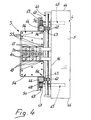
- said vertical movement device comprises pairs of double-action linear cylinders, such as the double-action hydraulic cylinders 10, which are arranged at the two uprights 3 and are provided with the upper end 11 of their pistons 12 suitably coupled by sperical joints 13 to the top 14 of the respective upright 3.
- the liners 15 of the cylinders 10 thus hang from the respective piston 12 and are vertically movable.
- the cylinders 10 are aligned along the longitudinal axis of the platforms 4 and the upper platform 4b is connected to the innermost pair of hydraulic cylinders 10, the underlying planes 4 being progressively coupled to the progressively outer pairs of cylinders 10.
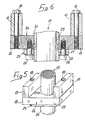
- each plate 20 is provided with a central hole which, being traversed by the respective liner 15, is provided with a lower lateral region 21 which is larger in diameter and couples with an arrestor abutment rigidly coupled to the liner 15; said arrestor abutment is suitably composed of the circumferentially protruding crown of a ring 22 which can be split, e.g., into two half-rings, and is accommodated in a matchingly shaped annular groove 23 provided on the outer surface 24 of the liner 15.
- the sliding of the plate 20 along the liner 15 is suitably prevented by a drilled plate 25 which, on the opposite side with respect to the plate 20, engages against the ring 22 and is coupled to the same plate 20 by appropriate securing means, such as screws 26.
- each pair of double-action cylinders 10 coupled to the same platform 4 or 4b or to the upper cover 8 if said cover is also vertically movable (see Fig. 9), is operated in a synchronized manner by means of a separate volumetric pump 27, e.g. of the piston type and preferably with a variable flow rate, with full zero setting, mechanically coupled to an electric motor 28.
- a separate volumetric pump 27 e.g. of the piston type and preferably with a variable flow rate, with full zero setting, mechanically coupled to an electric motor 28.
- An hydraulic safety device 29 is suitably inserted on the hydraulic circuit which connects the pump 27 to the respective cylinders 10, and comprises: a reducing valve which reduces the pressure of the hydraulic liquid between the primary circuit, where e.g. approximately 130 bar may occur, and the secondary circuit, where again approximately the pressure may be around 20 bar; a safety valve; a sequence valve which, hydraulically driven by the secondary circuit, activates the primary circuit only when the pressure of the secondary circuit reaches the required value and conversely inhibits the motion of the platforms 4 if the pressure in the secondary is not at the optimum value, e.g. due to tampering or to a malfunction of the reducing valve.
- An electric valve 30 is furthermore provided on the hydraulic circuit, and controls the automatic operation of the machine, and so is an adjustment valve 31 which, by allowing to modify the flow rate of hydraulic fluid, allows to adjust the speed of descent of the platforms 4.
- the secondary circuit sends in any case into the upper chamber of the related cylinders 10 a low-pressure flow of the hydraulic liquid, so as to always keep said upper chamber filled, even if the platform moves, e.g. in the conditions of depression vacuum, when raised due to the ascent of the underlying platforms 4.
- the hydraulic circuit is furthermore provided with an electric safety device, composed of a pressure switch on the secondary circuit, which blocks the motion of the platforms 4 if for any reason the hydraulic driving pressure in said secondary circuit should be lost; the electric safety device thus performs electrically the same function also performed by the safety valve.
- the lowermost platform 4a is not operated by the double-action cylinders 10 but is instead suitably supported and shifted, in the embodiments illustrated, by a pair of single-action cylinders 36 which, arranged below it, are provided with fixed liners 37 arranged as a base 38 for the framework 2, from which liners movable pistons 39 extend and engage with the lateral regions 40 of the lowermost platform 4a.
- the vertical motion of the platforms 4 may be guided by suitable guiding means provided on the framework 2, so that the platforms 4 move vertically and keep exactly parallel to themselves.
- said guiding means comprise a pair of transverse shafts 41, mounted freely rotatable on the shorter sides 16 of all the platforms 4 and eventually also of the upper cover 8, if movable; the transverse shafts 41 are provided at each end with a pinion 42 which engages with a complementary front set of teeth 43 of a double vertical rack 44 fixed to the uprights 3.
- the guiding means furthermore comprise a pair of longitudinal shafts 45, mounted freely rotatable on the longer sides 46 of all the platforms 4 and eventually of the upper cover 8; the longitudinal shafts 45 are also provided with toothed end wheels 47 which engage in the complementary lateral teeth 48 of the double rack 44
- the motion of the platforms 4 is furthermore controlled by a safety device which is preferably composed of bars 49 which, supported in an electrically insulated manner by the related supports 50 extend parallel to the lateral teeth 48 at such a distance as to allow the exact passage of the toothed wheels 47.
- a safety device which is preferably composed of bars 49 which, supported in an electrically insulated manner by the related supports 50 extend parallel to the lateral teeth 48 at such a distance as to allow the exact passage of the toothed wheels 47.
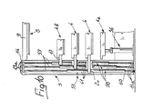
- Mechanical safety devices are furthermore provided on the uprights 3, which devices, as illustrated in Figure 8, are composed of pairs of bolts 51, arranged diagonally on the opposite sides of the two uprights 3, which are capable of supporting the entire weight of all the platforms 4 and of the eventual movable cover 8; the bolts 51 are operated by actuators 52, e.g. hydraulic or pneumatic, which alternately cause the reentry of said bolts 51, to allow the passage of the movable elements, and subsequently make the bolts 51 protrude from the uprights 3 until they project below the platforms 4, to block their descent in case of sudden severe breakdown
- actuators 52 e.g. hydraulic or pneumatic
- the pairs of double-action hydraulic cylinders 10 are suspended from the top 14 of the uprights 3 and support and move the related platforms 4, 4b and, eventually, the upper cover 8 connected thereto.
- the platforms 4 can thus move separately and spaced apart, or keeping one or more covers 6 in contact with the respective work surface 5, so as to keep operative the evaporation chamber provided thereby.
- the operation of the system may be controlled either manually, or in a semiautomatic or automatic manner, e.g. with preset work cycles; validation switches can be furthermore provided which follow the execution of all the various phases of the work cycles, requiring, to start a new type of work at the end of the preceding one the operation, on the part of the operator, of a suitable control means, such as, e.g., a pedal, a pushbutton or the like.
- the coupling of the pistons 12 by means of the spherical joints 13 allows a certain freedom of motion to the platforms 4 which, being subjected to the action exerted by their own weight, have self-centering characteristics which make them arrange spontaneously in the most appropriate position, and furthermore allows them to adapt to eventual imperfections of the guiding means and not to be affected by differential deformations due to different thermal expansions of the various parts of the machine.
- drying machine Another important advantage featured by the drying machine described lies in that it is possible to provide the two uprights 3 so that they might be disassembled, by means of a removable connection 53, by providing, e.g. as illustrated in Figure 8, approximately halfway along the height of the uprights 3, two flanges 54 joined by bolts 55 and coupled, at the racks 44, by centering pins 56.
- the possibility of moving vertically the lowermost platform 4a facilitates the access to the lower face of the platform 4a itself and to the inner components of the framework 2, thus simplifying many interventions, such as e.g. replacement or maintenance in general, which have to be performed on the machine 1.
- the system of movement which is the object of the invention uses elements, such as the linear double-action cylinders 10 or the spherical joints 13, which are available on the market, thus avoiding the design and the production of specific particular elements, with consequent benefits from the economical point of view.
- the linear double-action cylinders are composed of hydraulic cylinders 58 with a through piston 59.
- Their piston 59 extends for the entire length of the uprights 3 and is fixed, appropriately by means of pairs of spherical joints 13a, respectively to the top 14 and to the base 60 of the uprights 3.
- the liners 61 of the cylinders 58 are vertically movable and are coupled, similarly to what has been illustrated in Figures 5 and 6, to the smaller sides 16 of the platforms 4.
Landscapes
- Engineering & Computer Science (AREA)
- Mechanical Engineering (AREA)
- General Engineering & Computer Science (AREA)
- Manufacturing & Machinery (AREA)
- Chemical & Material Sciences (AREA)
- Organic Chemistry (AREA)
- Health & Medical Sciences (AREA)
- Life Sciences & Earth Sciences (AREA)
- Molecular Biology (AREA)
- Drying Of Solid Materials (AREA)
- Treatment And Processing Of Natural Fur Or Leather (AREA)
Claims (17)
Priority Applications (1)
| Application Number | Priority Date | Filing Date | Title |
|---|---|---|---|
| AT87902466T ATE64155T1 (de) | 1986-03-24 | 1987-03-19 | Vakuumtrockner fuer gegerbte haeute mit mehreren arbeitstischen. |
Applications Claiming Priority (2)
| Application Number | Priority Date | Filing Date | Title |
|---|---|---|---|
| IT85531/86A IT1204265B (it) | 1986-03-24 | 1986-03-24 | Macchina essicatrice sottovuoto a piu' piani di lavoro per pelli conciate |
| IT8553186 | 1986-03-24 |
Publications (2)
| Publication Number | Publication Date |
|---|---|
| EP0266380A1 EP0266380A1 (de) | 1988-05-11 |
| EP0266380B1 true EP0266380B1 (de) | 1991-06-05 |
Family
ID=11327604
Family Applications (1)
| Application Number | Title | Priority Date | Filing Date |
|---|---|---|---|
| EP87902466A Expired EP0266380B1 (de) | 1986-03-24 | 1987-03-19 | Vakuumtrockner für gegerbte häute mit mehreren arbeitstischen |
Country Status (8)
| Country | Link |
|---|---|
| US (1) | US5056239A (de) |
| EP (1) | EP0266380B1 (de) |
| JP (1) | JPH01500039A (de) |
| BR (1) | BR8706771A (de) |
| IT (1) | IT1204265B (de) |
| RU (1) | RU1776277C (de) |
| UA (1) | UA11212A (de) |
| WO (1) | WO1987005944A1 (de) |
Families Citing this family (13)
| Publication number | Priority date | Publication date | Assignee | Title |
|---|---|---|---|---|
| IT1233807B (it) * | 1989-02-15 | 1992-04-17 | Cartigliano Off Spa | Macchina essiccatrice sottovuoto a pianali multipli per pelli industriali e prodotti similari. |
| IT1270767B (it) * | 1993-03-18 | 1997-05-07 | Cartigliano Spa Off | Impianto a vuoto per esseccatoi di pelli industriali a pianali multipli ed essiccatoio incorporante tale impianto |
| IT1270914B (it) * | 1993-03-26 | 1997-05-16 | Cartigliano Spa Off | Impianto a vuoto stabilizzato per essicatoi di pelli industriali a pianali multipli |
| IT1267880B1 (it) * | 1994-11-15 | 1997-02-18 | Veeger Leander | Linea per l'alimentazione semiautomatica di macchine allargatrici/ asciugatrici, essicatrici e palissonatrici di pelli industriali. |
| US6038785A (en) * | 1998-01-16 | 2000-03-21 | Lawson; Richard R. | Vacuum drying screen |
| ITVI980127A1 (it) * | 1998-06-29 | 1999-12-29 | Cartigliano Off Spa | Impianto di essicazione ad alto vuoto equilibrato per pelli industria li e prodotti similari |
| CN1618716B (zh) * | 2003-11-12 | 2011-03-16 | 周星工程股份有限公司 | 装载锁及使用其的装载锁腔室 |
| KR101131417B1 (ko) * | 2003-11-12 | 2012-04-03 | 주성엔지니어링(주) | 로드락 장치 및 이를 설치한 로드락 챔버 |
| IT1391988B1 (it) * | 2008-11-20 | 2012-02-02 | Erretre Spa | Impianto migliorato per l'essicazione di superfici laminari flessibili. |
| ITVI20130009A1 (it) * | 2013-01-17 | 2014-07-18 | Cartigliano Off Spa | Apparato compatto per l'essicatura sotto vuoto di pelli industriali |
| US9119382B2 (en) * | 2013-02-26 | 2015-09-01 | Tyson Foods Inc. | Portable basket colony for growing and transport and method of use |
| ITVI20130138A1 (it) * | 2013-05-17 | 2014-11-18 | Cartigliano Off Spa | Essicatore a vuoto migliorato per pelli industriali |
| EP3294651A4 (de) * | 2015-05-11 | 2019-01-09 | Gebo Cermex Canada Inc. | Vertikale akkumulation in einer behandlungslinie |
Family Cites Families (8)
| Publication number | Priority date | Publication date | Assignee | Title |
|---|---|---|---|---|
| US3126578A (en) * | 1964-03-31 | board forming press and method of making board substitutes | ||
| US1536163A (en) * | 1919-10-07 | 1925-05-05 | Agasote Millboard Co | Apparatus for making sheets of pulp and similar articles |
| US1854341A (en) * | 1931-03-19 | 1932-04-19 | Birdsboro Steel Foundry & Mach | Press for fiber boards |
| US1907207A (en) * | 1931-08-15 | 1933-05-02 | Birdsboro Steel Foundry & Mach | Sheet transfer method and apparatus |
| GB1169532A (en) * | 1965-10-21 | 1969-11-05 | Hudson Ltd E W | Improvements in or relating to Leather Drying Machines |
| DE1604964A1 (de) * | 1966-08-10 | 1971-11-04 | Krauss Maffei Ag | Verfahren und Vorrichtung zum kontinuierlichen Gefriertrocknen rieselfaehiger Gueter |
| US3668819A (en) * | 1971-02-08 | 1972-06-13 | Pennwalt Corp | Vacuum drying and stoppering apparatus |
| US4480990A (en) * | 1983-06-27 | 1984-11-06 | At&T Technologies, Inc. | Article support rack and methods of weighting down articles |
-
1986
- 1986-03-24 IT IT85531/86A patent/IT1204265B/it active
-
1987
- 1987-03-19 WO PCT/EP1987/000155 patent/WO1987005944A1/en not_active Ceased
- 1987-03-19 BR BR8706771A patent/BR8706771A/pt not_active IP Right Cessation
- 1987-03-19 EP EP87902466A patent/EP0266380B1/de not_active Expired
- 1987-03-19 JP JP62502386A patent/JPH01500039A/ja active Pending
- 1987-03-19 UA UA4203741A patent/UA11212A/uk unknown
- 1987-11-23 RU SU874203741A patent/RU1776277C/ru active
-
1989
- 1989-10-03 US US07/416,385 patent/US5056239A/en not_active Expired - Fee Related
Also Published As
| Publication number | Publication date |
|---|---|
| US5056239A (en) | 1991-10-15 |
| WO1987005944A1 (en) | 1987-10-08 |
| EP0266380A1 (de) | 1988-05-11 |
| BR8706771A (pt) | 1988-02-23 |
| JPH01500039A (ja) | 1989-01-12 |
| RU1776277C (ru) | 1992-11-15 |
| UA11212A (uk) | 1996-12-25 |
| IT8685531A0 (it) | 1986-03-24 |
| IT1204265B (it) | 1989-03-01 |
Similar Documents
| Publication | Publication Date | Title |
|---|---|---|
| US5056239A (en) | Vacuum drying machine for tanned skins, with multiple work surfaces | |
| US4304540A (en) | Hydraulic press | |
| RU2039919C1 (ru) | Вакуумная сушильная установка | |
| US3895778A (en) | Method of lowering and raising loads by means of a jack assembly and lifting element | |
| US3091305A (en) | Hydraulically operated portable scaffold | |
| CN108247815A (zh) | 一种全自动保温板成型装置 | |
| US4318811A (en) | Kettle filter | |
| US2511184A (en) | Automatic valve timer | |
| US3252409A (en) | Fixed box cotton press | |
| CN207684804U (zh) | 剪式举升机 | |
| CN218087914U (zh) | 一种码垛机器人传输部件 | |
| US4516333A (en) | Device for controlling the position of product containers carrying plates of a lyophilization and the like apparatus | |
| US4455931A (en) | Apparatus and method for processing raw fiber stock | |
| US3088394A (en) | Apparatus for extracting soluble constituents from vegetable matter | |
| KR20160010282A (ko) | 산업용 하이드를 위한 개선된 진공 드라이어 | |
| CN208361128U (zh) | 直角转弯自动理料系统 | |
| CN202800369U (zh) | 一种制鞋贴底生产线设备 | |
| US2973106A (en) | Apparatus for lifting and setting down of moulding boxes | |
| CN206765418U (zh) | 一种多腔双工位艾饼热压成型机 | |
| CN106871580B (zh) | 一种安全智能型通过式真空干燥机 | |
| CN108190537A (zh) | 空托盘拆码分器 | |
| RU2060395C1 (ru) | Способ корректировки положения секции механизированной крепи очистного комбайнового комплекса | |
| CN220463735U (zh) | 一种罗茨风机拆卸工具 | |
| CN212884145U (zh) | 一种便于固定球铁铸件轧辊的固定装置 | |
| CN216497551U (zh) | 一种精馏再沸的热泵循环系统 |
Legal Events
| Date | Code | Title | Description |
|---|---|---|---|
| PUAI | Public reference made under article 153(3) epc to a published international application that has entered the european phase |
Free format text: ORIGINAL CODE: 0009012 |
|
| AK | Designated contracting states |
Kind code of ref document: A1 Designated state(s): AT BE CH DE FR GB IT LI LU NL SE |
|
| 17P | Request for examination filed |
Effective date: 19880325 |
|
| 17Q | First examination report despatched |
Effective date: 19900517 |
|
| GRAA | (expected) grant |
Free format text: ORIGINAL CODE: 0009210 |
|
| ITF | It: translation for a ep patent filed | ||
| AK | Designated contracting states |
Kind code of ref document: B1 Designated state(s): AT BE CH DE FR GB IT LI LU NL SE |
|
| PG25 | Lapsed in a contracting state [announced via postgrant information from national office to epo] |
Ref country code: SE Effective date: 19910605 Ref country code: LI Effective date: 19910605 Ref country code: CH Effective date: 19910605 Ref country code: BE Effective date: 19910605 |
|
| REF | Corresponds to: |
Ref document number: 64155 Country of ref document: AT Date of ref document: 19910615 Kind code of ref document: T |
|
| REF | Corresponds to: |
Ref document number: 3770580 Country of ref document: DE Date of ref document: 19910711 |
|
| ET | Fr: translation filed | ||
| REG | Reference to a national code |
Ref country code: CH Ref legal event code: PL |
|
| PLBE | No opposition filed within time limit |
Free format text: ORIGINAL CODE: 0009261 |
|
| STAA | Information on the status of an ep patent application or granted ep patent |
Free format text: STATUS: NO OPPOSITION FILED WITHIN TIME LIMIT |
|
| 26N | No opposition filed | ||
| EPTA | Lu: last paid annual fee | ||
| PGFP | Annual fee paid to national office [announced via postgrant information from national office to epo] |
Ref country code: LU Payment date: 19950301 Year of fee payment: 9 |
|
| PGFP | Annual fee paid to national office [announced via postgrant information from national office to epo] |
Ref country code: GB Payment date: 19950324 Year of fee payment: 9 |
|
| PGFP | Annual fee paid to national office [announced via postgrant information from national office to epo] |
Ref country code: FR Payment date: 19950329 Year of fee payment: 9 Ref country code: AT Payment date: 19950329 Year of fee payment: 9 |
|
| PGFP | Annual fee paid to national office [announced via postgrant information from national office to epo] |
Ref country code: NL Payment date: 19950331 Year of fee payment: 9 |
|
| PGFP | Annual fee paid to national office [announced via postgrant information from national office to epo] |
Ref country code: DE Payment date: 19950428 Year of fee payment: 9 |
|
| PG25 | Lapsed in a contracting state [announced via postgrant information from national office to epo] |
Ref country code: LU Free format text: LAPSE BECAUSE OF NON-PAYMENT OF DUE FEES Effective date: 19960319 Ref country code: GB Effective date: 19960319 Ref country code: AT Effective date: 19960319 |
|
| PG25 | Lapsed in a contracting state [announced via postgrant information from national office to epo] |
Ref country code: NL Effective date: 19961001 |
|
| GBPC | Gb: european patent ceased through non-payment of renewal fee |
Effective date: 19960319 |
|
| PG25 | Lapsed in a contracting state [announced via postgrant information from national office to epo] |
Ref country code: FR Effective date: 19961129 |
|
| NLV4 | Nl: lapsed or anulled due to non-payment of the annual fee |
Effective date: 19961001 |
|
| PG25 | Lapsed in a contracting state [announced via postgrant information from national office to epo] |
Ref country code: DE Effective date: 19961203 |
|
| REG | Reference to a national code |
Ref country code: FR Ref legal event code: ST |
|
| PGFP | Annual fee paid to national office [announced via postgrant information from national office to epo] |
Ref country code: IT Payment date: 20060331 Year of fee payment: 20 |