EP0266442A1 - Verlegeeinrichtung - Google Patents
Verlegeeinrichtung Download PDFInfo
- Publication number
- EP0266442A1 EP0266442A1 EP86115189A EP86115189A EP0266442A1 EP 0266442 A1 EP0266442 A1 EP 0266442A1 EP 86115189 A EP86115189 A EP 86115189A EP 86115189 A EP86115189 A EP 86115189A EP 0266442 A1 EP0266442 A1 EP 0266442A1
- Authority
- EP
- European Patent Office
- Prior art keywords
- rollers
- laying
- carriage
- laying device
- guiding
- Prior art date
- Legal status (The legal status is an assumption and is not a legal conclusion. Google has not performed a legal analysis and makes no representation as to the accuracy of the status listed.)
- Granted
Links
- 239000000463 material Substances 0.000 claims abstract description 10
- 238000006073 displacement reaction Methods 0.000 abstract 1
- 238000001816 cooling Methods 0.000 description 4
- 238000005520 cutting process Methods 0.000 description 3
- 238000010276 construction Methods 0.000 description 2
- 238000004519 manufacturing process Methods 0.000 description 2
- 235000004443 Ricinus communis Nutrition 0.000 description 1
- 240000000528 Ricinus communis Species 0.000 description 1
- 238000000034 method Methods 0.000 description 1
- 238000011144 upstream manufacturing Methods 0.000 description 1
Images


Classifications
-
- B—PERFORMING OPERATIONS; TRANSPORTING
- B65—CONVEYING; PACKING; STORING; HANDLING THIN OR FILAMENTARY MATERIAL
- B65H—HANDLING THIN OR FILAMENTARY MATERIAL, e.g. SHEETS, WEBS, CABLES
- B65H45/00—Folding thin material
- B65H45/02—Folding limp material without application of pressure to define or form crease lines
- B65H45/06—Folding webs
- B65H45/10—Folding webs transversely
- B65H45/101—Folding webs transversely in combination with laying, i.e. forming a zig-zag pile
- B65H45/103—Folding webs transversely in combination with laying, i.e. forming a zig-zag pile by a carriage which reciprocates above the laying station
Definitions
- the present invention relates to a laying device for palletizing a running web of material, for example unvulcanized rubber, with a height-adjustable guide device having at least two laying rollers, the laying rollers forming an active gap, rotatably mounted and drivable and on a carriage or slide that can be moved back and forth on a laying frame are set.
- a height-adjustable guide device having at least two laying rollers, the laying rollers forming an active gap, rotatably mounted and drivable and on a carriage or slide that can be moved back and forth on a laying frame are set.
- the endless tubular rubber web coming from a rubber cooling system is continuously or intermittently fed into the guide device via a conveying device, gripped by the laying rollers and deposited on a pallet or the like by their horizontal back and forth method.
- the raw rubber sheet As it passes through the rubber cooling system, the raw rubber sheet is cut into longitudinal strips, with the exception of a small, perforation-like layer, the width of which corresponds to the requirements of further processing. Because the individual strip tracks are separated from each other during further processing are separated, a stacking of the material web with the same cut edge is desirable, since this is the only way to remove the individual strip webs smoothly and without interruption, which improves the production process and thus results in a more efficient way of working.
- the present invention is therefore based on the object of designing a laying device of the generic type in such a way that the material web is cut-edge-straight or centered on the pallet with the simplest design means and its subsequent removal for further processing is thus trouble-free and therefore more cost-effective.
- this object is achieved in that the guide device has a centering device above the laying rollers, with which the center of the web can be guided in a constant manner.
- This construction ensures that the center course of the web to be transported by the laying rollers is always the same. Since the cutting process of the cut strips is also aligned with the middle of the web by a cutting unit in the upstream rubber cooling system, exact palletizing along the cutting edges is guaranteed.
- a particularly simple but effective embodiment of the invention provides that the centering device consists of two opposing guide rollers arranged transversely to the laying rollers, which are pressed against the side edges of the web and in their position of use Position can be changed simultaneously in the opposite direction and by the same distance.
- this construction offers further advantages.
- it is extremely inexpensive to manufacture, and on the other hand, its operational reliability is very high, since the center position control of the material web is carried out exclusively by mechanical parts, which in particular under the aspect of the extremely harsh operating conditions that prevail when processing rubber webs, a trouble-free operation enable.
- the laying device shown in the figures consists in its basic structure of a frame which is fixed with its rear vertical spar 3 to a rubber cooling system (not shown), a horizontal laying frame 10 which has one end in the spars 3 and is height adjustable by means of a pressure cylinder 2.
- a carriage 20 provided with castors 21 can be moved horizontally back and forth in the laying frame 10.
- two articulated arms 31 are each pivotally fixed at one end, while their other ends are arranged on the opposite rotatable laying rollers 30, which form an active gap and can be driven.
- At least a pair of the articulated arms 31 are connected to one another by a pressure cylinder 32, so that the laying rollers 30 change their distance from one another when the pressure cylinder 32 is actuated.
- a centering device is provided above the laying rollers 30, with which the material web, in the present exemplary embodiment the rubber web 5, can be guided in a constant manner in its central course.
- the centering device consists of two opposite guide rollers 40 arranged transversely to the laying rollers 30, which in the position of use are pressed onto the side edges of the rubber sheet 5 with the same pressure.
- Each guide roller 40 is fixed to a roller carriage 43, the rollers 44 of which are guided in a holding frame 42 and can be moved transversely to the running direction of the rubber sheet 5.
- the holding frame 42 is fastened to the latter in the region between the laying rollers 30 and the carriage 20, so that the reciprocating movement of the carriage 20 and the laying rollers 30 is also carried out by the holding frame 42.
- the force to press the guide rollers 40 against the rubber web 5 is generated by a pressure cylinder 41, preferably a pneumatic cylinder, the cylinder of which is fixedly connected to the carriage 20 via a flange 46 and the piston of which is firmly connected to a roller carriage 43 via a plate 45.
- a chain tensioner 50 is also arranged on the bracket 45, as is a driver 47 which is connected to the other roller carriage 43.
- two deflection wheels 49 which are designed as chain wheels in the present exemplary embodiment, are fixed on the holding frame 42.
- a chain 48 is guided over the deflection wheels 49 facing away from the piston of the pressure cylinder 41, one end of which is connected to the driver 47 and the other end of which is connected to the chain tensioner 50, which is fixed to the plate 45.
- a chain 51 which is connected on the one hand to the chain tensioner 50, which is connected to the driver 47, and on the other hand is fastened to the plate 45, is also guided over the opposite deflection wheels 49.
- the use of, for example, a traction cable or the like is also conceivable, in which case the deflection wheels 49 must be designed accordingly.
- the lifting movements of the printing cylinder can be coupled to one another, for example, with the position of the laying rollers 30. Thereafter, when the laying rollers 30 are in a spread position, in which the rubber sheet 5 is inserted, the pressure cylinder 41 is switched so that the piston of the pressure cylinder 41 reaches an extended end position. As a result, the roller carriage 43 coupled directly to the piston also becomes an outermost position moved, as the opposite roller carriage 43 by the chain hoist exerted by the chain tensioner connected to the plate 45 50 is transferred to the chain 48.
- the pressure cylinder 41 is provided with a quick exhaust valve, which is effective when moving apart, so that the two roller carriages 43 are moved apart correspondingly quickly.
- the pressure cylinder 41 also moves together, so that the roller carriage 43 drawn directly by the piston of the pressure cylinder 41 moves in the direction of the rubber track 5, while the movement of the other roller carriage 43, likewise in the direction of the rubber track 5, by pulling the chain 51 is effected, which, as already described, is fixed on the one hand to the link plate 45 and on the other hand to the chain tensioner 50 of the driver 47.
- Characteristic of the route changes of the roller carriages 43 is their simultaneous and in the opposite direction changing position.
- a stop for the guide rollers 40 when they move towards the rubber sheet 5 is formed by their respective side edges.
- the guide rollers 40 are pressed onto the side edges at a relatively low pressure, for example 0.8 bar, in order to prevent the side edges from buckling.
- the rubber track 5 is pressed into a position by the rotatably mounted return roller 40 associated with the changed run or the changed contour of the side edge, in cooperation with the opposite guide roller 40, which position corresponds exactly to the predetermined center course.
Landscapes
- Tyre Moulding (AREA)
- Folding Of Thin Sheet-Like Materials, Special Discharging Devices, And Others (AREA)
- Computer And Data Communications (AREA)
- Crystals, And After-Treatments Of Crystals (AREA)
- Vehicle Body Suspensions (AREA)
- Farming Of Fish And Shellfish (AREA)
- Catching Or Destruction (AREA)
- Registering, Tensioning, Guiding Webs, And Rollers Therefor (AREA)
Abstract
Description
- Die vorliegende Erfindung betrifft eine Verlegeeinrichtung zum Palettieren einer laufenden Warenbahn aus beispielsweise unvulkanisiertem Gummi, mit einer höhenverstellbaren, mindestens zwei Verlegewalzen aufweisenden Führungsvorrichtung, wobei die Verlegewalzen einen Wirkspalt bilden, drehbar gelagert und antreibbar und an einem auf einem Verlegerahmen hin- und herfahrbaren Wagen oder Schlitten festgelegt sind.
- Bei derartigen Verlegeeinrichtungen wird die aus einer Gummikühlanlage kommende, endlose Rohrgummibahn kontinuierlich oder taktweise über eine Fördereinrichtung in die Führungsvorrichtung geführt, von den Verlegewalzen ergriffen und durch deren horizontales Hin- und Herverfahren auf einer Palette od. dgl. abgelegt.
- Die Rohgummibahn wird beim Durchlauf durch die Gummikühlanlage bis auf eine geringe, einer Perforation ähnelnde Schicht in Längsstreifen geschnitten, die in ihrer Breite den Erfordernissen der Weiterverarbeitung entsprechen.
Da die einzelnen Streifenbahnen bei der Weiterverarbeitung voneinander getrennt werden, ist eine schnittkantengleiche Stapelung der Warenbahn wünschenswert, da nur so ein flüssiges und unterbrechungsfreies Entnehmen der einzelnen Streifenbahnen möglich ist, was eine Verbesserung des Produktionsablaufes und somit eine rationellere Arbeitsweise zufolge hat. - Der vorliegenden Erfindung liegt daher die Aufgabe zugrunde, eine Verlegeeinrichtung der gattungsgemäßen Art so zu gestalten, daß mit konstruktiv einfachsten Mitteln die Warenbahn schnittkantengerade bzw. mittengenau palettiert wird und somit ihre anschließende Entnahme zur Weiterverarbeitung störungsfrei und damit kostengünstiger möglich ist.
- Diese Aufgabe wird erfindungsgemäß dadurch gelöst, daß die Führungsvorrichtung oberhalb der Verlegewalzen eine Zentriereinrichtung aufweist, mit der die Warenbahn in ihrem Mittenverlauf gleichbleibend führbar ist.
- Durch diese Konstruktion wird gewährleistet, daß der Mittenverlauf der von den Verlegewalzen zu transportierenden Warenbahn immer gleich ist. Da der Schnittverlauf der angeschnittenen Streifen durch ein Schneidwerk in der vorgeschalteten Gummikühlanlage sich ebenfalls an der Warenbahnmitte ausrichtet, ist ein exaktes Palettieren entlang der Schnittkanten gewährleistet.
- Eine besonders einfache aber wirkungsvolle Ausgestaltung der Erfindung sieht vor, daß die Zentriereinrichtung aus zwei sich gegenüberliegenden, quer zu den Verlegewalzen angeordneten Führungsrollen besteht, die in Gebrauchsstellung an die Seitenkanten der Warenbahn angedrückt sind und in ihrer Lage gleichzeitig in entgegengesetzter Richtung und um die gleiche Strecke veränderbar sind.
Neben der absolut sicheren Mittenzentrierung der Warenbahn durch die so gestaltete Zentriereinrichtung, bietet diese Konstruktion noch weitere Vorteile. Einmal ist sie in der Herstellung äußerst preiswert, zum anderen ist ihre Betriebssicherheit sehr hoch, da die Mittenlagesteuerung der Warenbahn hierbei ausschließlich durch mechanische Teile erfolgt, die insbesondere unter dem Aspekt der ungemein rauhen Betriebsbedingungen, die bei der Verarbeitung von Gummibahnen herrschen, einen störungsfreien Betriebsablauf ermöglichen. - Weitere vorteilhafte Ausgestaltungen der Erfindung sind in den Unteransprüchen gekennzeichnet.
- Ein Ausführungsbeispiel der Erfindung wird nachfolgend anhand beigefügter Zeichnungen beschrieben.
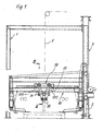
Es zeigen: - Fig. 1 eine Seitenansicht der erfindungsgemäß ausgebildeten Verlegeeinrichtung,
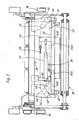
- Fig. 2 eine Draufsicht auf die Verlegeeinrichtung,
- Fig. 3 einen Schnitt durch die Verlegeeinrichtung gemäß der Linie III-III in Fig. 1,
- Fig. 4 einen Schnitt durch die Verlegeeinrichtung gemäß der Linie IV-IV in Fig. 2.
- Die in den Figuren dargestellte Verlegeeinrichtung besteht in i hrem Grundaufbau aus einem Gestellll, das mit seinem hinteren vertikalen Holm 3 an einer nicht dargestellten Gummikühlanlage festgelegt ist, einem horizontalen Verlegerahmen 10, der mit einem Ende in den Holmen 3 geführt ist und mittels eines Druckzylinders 2 höhenverstellbar ist.
- Ein mit Laufrollen 21 versehener Wagen 20 ist in dem Verlegerahmen 10 horizontal hin und her verfahrbar.
An den quer zur Verfahrrichtung liegenden Seiten des Wagens 20 sind jeweils zwei Gelenkarme 31 mit ihrem einen Ende schwenkbar festgelegt, während sie mit ihrem anderen Ende an den jeweils gegenüberliegenden drehbaren Verlegewalzen 30 angeordnet sind, die einen Wirkspalt bilden und antreibbar sind.
Mindestens ein Paar der Gelenkarme 31 sind durch einen Druckzylinder 32 miteinander verbunden, so daß die Verlegewalzen 30 bei Betätigung des Druckzylinders 32 ihren Abstand zueinander verändern. - Erfindungsgemäß ist oberhalb der Verlegewalzen 30 eine Zentriereinrichtung vorgesehen, mit der die Warenbahn, im vorliegenden Ausführungsbeispiel die Gummibahn 5 in ihrem Mittenverlauf gleichbleibend führbar ist. Wie insbesondere die Figuren 3 und 4 zeigen, besteht die Zentriereinrichtung aus zwei sich gegenüberliegenden, quer zu den Verlegewalzen 30 angeordneten Führungsrollen 40, die in Gebrauchsstellung an die Seitenkanten der Gummibahn 5 mit gleichem Druck angedrückt sind.
Jede Führungsrolle 40 ist an einem Rollenwagen 43 festgelegt, dessen Rollen 44 in einem Halterahmen 42 geführt sind und quer zur Laufrichtung der Gummibahn 5 verfahrbar ist. Der Halterahmen 42 ist im Bereich zwischen den Verlegewalzen 30 und dem Wagen 20 an diesem befestigt, so daß die Hin-und Herbewegung des Wagens 20 und der Verlegewalzen 30 von dem Halterahmen 42 ebenfalls ausgeführt wird. - Die Kraft zum Andrücken der Führungsrollen 40 an die Gummi bahn 5 wird durch einen Druckzylinder 41, vorzugsweise einen pneumatischen Zylinder erzeugt, dessen Zylinder über einen Flansch 46 mit dem Wagen 20 und dessen Kolben über eine Lasche 45 mit einem Rollenwagen 43 fest verbunden ist. An der Lasche 45 ist ebenso ein Kettenspanner 50 angeordnet, wie an einem Mitnehmer 47, der an dem anderen Rollenwagen 43 angeschlossen ist. Im Bereich jedes Rollenwagens 43 sind jeweils zwei Umlenkräder 49, die im vorliegenden Ausführungsbeispiel als Kettenräder ausgebildet sind, am Halterahmen 42 festgelegt. Über die dem Kolben des Druckzylinders 41 abgewandten Umlenkräder 49 ist eine Kette 48 geführt, deren eines Ende mit dem Mitnehmer 47 und deren anderes Ende mit dem Kettenspanner 50 verbunden ist, der an der Lasche 45 festgelegt ist.
Über die gegenüberliegenden Umlenkräder 49 wird ebenfalls eine Kette 51 geführt, die einerseits an dem Kettenspanner 50 angeschlossen ist, der mit dem Mitnehmer 47 verbunden ist, und andererseits an der Lasche 45 befestigt ist.
Neben einer Kette ist auch der Einsatz beispielsweise eines Zugseiles od. dgl. denkbar, wobei dann die Umlenkräder 49 entsprechend gestaltet sein müssen. - Die Hubbewegungen des Druckzylinders können beispielsweise mit der Stellung der Verlegewalzen 30 zueinander gekoppelt sein. Danach ist bei einer gespreizten Stellung der Verlegewalzen 30, in der die Gummibahn 5 eingeführt wird, der Druckzylinder 41 so geschaltet, daß der Kolben des Druckzylinders 41 eine ausgefahrene Endstellung erreicht.Dadurch wird der direkt an den Kolben angekoppelte Rollenwagen 43 ebenso in eine äußerste Position verschoben, wie der gegenüberliegende Rollenwagen 43 durch den ausgeübten Kettenzug, der durch den an der Lasche 45 angeschlossenen Kettenspanner 50 auf die Kette 48 übertragen wird. Vorzugsweise ist der Druckzylinder 41 mit einem Schnellentlüftungsventil versehen, das beim Auseinanderfahren wirksam wird, so daß die beiden Rollenwagen 43 entsprechend schnell auseinander gefahren werden.
- Beim Zusammenfahren der Verlegewalzen 30 fährt auch der Druckzylinder 41 zusammen, so daß der direkt durch den Kolben des Druckzylinders 41 gezogene R ollenwagen 43 sich in Richtung der Gummibahn 5 bewegt während die ebenfalls in Richtung der Gummibahn 5 verlaufende Bewegung des anderen Rollenwagens 43 durch ein Ziehen der Kette 51 bewirkt wird, die, wie bereits beschrieben, einerseits an der Lasche 45 und andererseits an dem Kettenspanner 50 des Mitnehmers 47 festgelegt ist. Charakteristisch bei den Streckenveränderungen der Rollenwagen 43 ist ihre gleichzeitige und in entgegengesetzter Richtung erfolgende Lageveränderung.
Einen Anschlag für die Führungsrollen 40 bei ihrer Verschiebung zur Gummibahn 5 hin, bilden deren jeweilige Seitenkanten. Dabei werden die Führungsrollen 40 mit relativ geringem Druck, beispielsweise mit 0,8 bar, an die Seitenkanten angedrückt, um so ein Einknicken der Seitenkanten zu vermeiden. - Bei einer Lage- oder Konturveränderung der Gummibahn 5 wird durch die dem veränderten Lauf bzw. der veränderten Kontur der Seitenkante zugeordnete drehbar gelagerte Rückführungsrolle 40 im Zusammenwirken mit der gegenüberliegenden Führungsrolle 40, die Gummibahn 5 in eine Position gedrückt, die exakt dem vorgegebenen Mittenverlauf entspricht.
Claims (10)
Priority Applications (6)
| Application Number | Priority Date | Filing Date | Title |
|---|---|---|---|
| EP86115189A EP0266442B1 (de) | 1986-11-03 | 1986-11-03 | Verlegeeinrichtung |
| ES86115189T ES2012335B3 (es) | 1986-11-03 | 1986-11-03 | Sistema de reubicacion |
| DE8686115189T DE3668311D1 (de) | 1986-11-03 | 1986-11-03 | Verlegeeinrichtung. |
| AT86115189T ATE49577T1 (de) | 1986-11-03 | 1986-11-03 | Verlegeeinrichtung. |
| US07/067,618 US4834359A (en) | 1986-11-03 | 1987-06-26 | Palletizing apparatus for web stock and the like |
| GR90400010T GR3000309T3 (en) | 1986-11-03 | 1990-01-18 | Folding and laying apparatus |
Applications Claiming Priority (1)
| Application Number | Priority Date | Filing Date | Title |
|---|---|---|---|
| EP86115189A EP0266442B1 (de) | 1986-11-03 | 1986-11-03 | Verlegeeinrichtung |
Publications (2)
| Publication Number | Publication Date |
|---|---|
| EP0266442A1 true EP0266442A1 (de) | 1988-05-11 |
| EP0266442B1 EP0266442B1 (de) | 1990-01-17 |
Family
ID=8195561
Family Applications (1)
| Application Number | Title | Priority Date | Filing Date |
|---|---|---|---|
| EP86115189A Expired - Lifetime EP0266442B1 (de) | 1986-11-03 | 1986-11-03 | Verlegeeinrichtung |
Country Status (6)
| Country | Link |
|---|---|
| US (1) | US4834359A (de) |
| EP (1) | EP0266442B1 (de) |
| AT (1) | ATE49577T1 (de) |
| DE (1) | DE3668311D1 (de) |
| ES (1) | ES2012335B3 (de) |
| GR (1) | GR3000309T3 (de) |
Families Citing this family (3)
| Publication number | Priority date | Publication date | Assignee | Title |
|---|---|---|---|---|
| US5056246A (en) * | 1989-10-27 | 1991-10-15 | Nikolaus Balonier | Device for taking trousers off an ironing machine |
| US5695457A (en) * | 1994-07-28 | 1997-12-09 | Heartport, Inc. | Cardioplegia catheter system |
| DE602005017185D1 (de) * | 2004-08-20 | 2009-11-26 | Ranpak Corp | Maschine und verfahren zur herstellung von polsterelementen |
Citations (3)
| Publication number | Priority date | Publication date | Assignee | Title |
|---|---|---|---|---|
| DE1785576A1 (de) * | 1962-08-16 | 1973-01-04 | Ruedgisch Edgar Von | Vorrichtung zur selbsttaetigen geradefuehrung von stoffbahnen |
| US3917250A (en) * | 1973-06-21 | 1975-11-04 | Applied Power Inc | Strip laying apparatus |
| GB2006167A (en) * | 1977-10-14 | 1979-05-02 | Gretag Ag | Strip guiding device |
Family Cites Families (3)
| Publication number | Priority date | Publication date | Assignee | Title |
|---|---|---|---|---|
| GB937511A (en) * | 1961-01-17 | 1963-09-25 | Akos Laszlo | Apparatus for transversely guiding bands of sheet material |
| DE3422352A1 (de) * | 1984-06-15 | 1985-12-19 | Stig Axel 8000 München Landgren | Vorrichtung zum aufschichten eines angenaehert flachbreiten stranges zu einem etwa quaderfoermigen block |
| FR2579962B1 (de) * | 1985-04-04 | 1987-07-03 | Lectra Systemes Sa |
-
1986
- 1986-11-03 DE DE8686115189T patent/DE3668311D1/de not_active Expired - Fee Related
- 1986-11-03 ES ES86115189T patent/ES2012335B3/es not_active Expired - Lifetime
- 1986-11-03 EP EP86115189A patent/EP0266442B1/de not_active Expired - Lifetime
- 1986-11-03 AT AT86115189T patent/ATE49577T1/de active
-
1987
- 1987-06-26 US US07/067,618 patent/US4834359A/en not_active Expired - Fee Related
-
1990
- 1990-01-18 GR GR90400010T patent/GR3000309T3/el unknown
Patent Citations (3)
| Publication number | Priority date | Publication date | Assignee | Title |
|---|---|---|---|---|
| DE1785576A1 (de) * | 1962-08-16 | 1973-01-04 | Ruedgisch Edgar Von | Vorrichtung zur selbsttaetigen geradefuehrung von stoffbahnen |
| US3917250A (en) * | 1973-06-21 | 1975-11-04 | Applied Power Inc | Strip laying apparatus |
| GB2006167A (en) * | 1977-10-14 | 1979-05-02 | Gretag Ag | Strip guiding device |
Also Published As
| Publication number | Publication date |
|---|---|
| ATE49577T1 (de) | 1990-02-15 |
| EP0266442B1 (de) | 1990-01-17 |
| US4834359A (en) | 1989-05-30 |
| DE3668311D1 (de) | 1990-02-22 |
| ES2012335B3 (es) | 1990-03-16 |
| GR3000309T3 (en) | 1991-06-07 |
Similar Documents
| Publication | Publication Date | Title |
|---|---|---|
| DE2555425C2 (de) | Vorrichtung zum Einschlagen von Papierriesen | |
| EP0377833B1 (de) | Greifvorrichtung zum Mitführen einer klebrigen Werkstoffbahn | |
| DE3202914A1 (de) | Laengsschneide- und/oder rillmaschine fuer bewegte materialbahnen, insbesondere fuer wellpappebahnen | |
| DE3142378C2 (de) | ||
| DE1729773A1 (de) | Maschine zum Schneiden von gummiertem Gewebe od. dgl. | |
| DE3246129A1 (de) | Vorrichtung zum genauen anhalten von fahrzeugen | |
| DE3318314A1 (de) | Vorrichtung zum trennen der einzelnen zuschnitte eines stapels gestanzter blaetter | |
| DE2555712C2 (de) | Regalförderzeug für ein Hochregallager | |
| DE1805239B2 (de) | Einer mehrstranggiessanlage nachgeordnete quertransporteinrichtung fuer abgetrennte strangabschnitte | |
| EP0266442B1 (de) | Verlegeeinrichtung | |
| DE3125885C2 (de) | Ablenkvorrichtung für Stückgut | |
| CH652377A5 (en) | Apparatus for transferring workpiece supports, workpieces or the like between transport tracks arranged transversely or parallel to each other | |
| DE1902619A1 (de) | Vorrichtung zum Zusammendruecken und Bandagieren einer Drahtspule | |
| EP0564971B1 (de) | Vorrichtung und Verfahren zur Bildung eines Gutstapels | |
| DE3620290A1 (de) | Linearantriebseinheit | |
| DE3248574A1 (de) | Querschneider zum durchtrennen von folienbahnen z.b. in verpackungsmaschinen | |
| DE2036266C3 (de) | Einer Stranggießkokille nachgeordnete Strangführung | |
| DE2217140B1 (de) | Vorrichtung zum auslegen und querschneiden von stoffbahnen | |
| DE3442943A1 (de) | Vorrichtung zum falten der oeffnung von gefuellten saecken | |
| DE19647012B4 (de) | Sägekopf zum Schneiden linear bewegten Materials in Querrichtung | |
| DE1574326C (de) | Vorrichtung zum Zuführen eines Spne gelbandes zu emer Wagenhimmelbahn | |
| DE1940308A1 (de) | Vorrichtung zum Laengsbewegen von langen Schienenabschnitten | |
| DE4237316A1 (de) | Einrichtung zum Umsetzen von Blechteilen in einer Pressenanlage | |
| DE2126700C2 (de) | Anhaltestation für eine Schleppkettenkreisförderanlage | |
| EP0159622A2 (de) | Siebdruckmaschine mit einem festen Drucktisch |
Legal Events
| Date | Code | Title | Description |
|---|---|---|---|
| PUAI | Public reference made under article 153(3) epc to a published international application that has entered the european phase |
Free format text: ORIGINAL CODE: 0009012 |
|
| AK | Designated contracting states |
Kind code of ref document: A1 Designated state(s): AT BE CH DE ES FR GB GR IT LI LU NL SE |
|
| 17P | Request for examination filed |
Effective date: 19880428 |
|
| 17Q | First examination report despatched |
Effective date: 19880722 |
|
| ITF | It: translation for a ep patent filed | ||
| GRAA | (expected) grant |
Free format text: ORIGINAL CODE: 0009210 |
|
| AK | Designated contracting states |
Kind code of ref document: B1 Designated state(s): AT BE CH DE ES FR GB GR IT LI LU NL SE |
|
| REF | Corresponds to: |
Ref document number: 49577 Country of ref document: AT Date of ref document: 19900215 Kind code of ref document: T |
|
| GBT | Gb: translation of ep patent filed (gb section 77(6)(a)/1977) | ||
| REF | Corresponds to: |
Ref document number: 3668311 Country of ref document: DE Date of ref document: 19900222 |
|
| ET | Fr: translation filed | ||
| REG | Reference to a national code |
Ref country code: GR Ref legal event code: FG4A Free format text: 3000309 |
|
| PLBE | No opposition filed within time limit |
Free format text: ORIGINAL CODE: 0009261 |
|
| STAA | Information on the status of an ep patent application or granted ep patent |
Free format text: STATUS: NO OPPOSITION FILED WITHIN TIME LIMIT |
|
| 26N | No opposition filed | ||
| ITTA | It: last paid annual fee | ||
| PGFP | Annual fee paid to national office [announced via postgrant information from national office to epo] |
Ref country code: SE Payment date: 19921012 Year of fee payment: 7 |
|
| PGFP | Annual fee paid to national office [announced via postgrant information from national office to epo] |
Ref country code: LU Payment date: 19921014 Year of fee payment: 7 |
|
| PGFP | Annual fee paid to national office [announced via postgrant information from national office to epo] |
Ref country code: GR Payment date: 19921016 Year of fee payment: 7 |
|
| PGFP | Annual fee paid to national office [announced via postgrant information from national office to epo] |
Ref country code: CH Payment date: 19921021 Year of fee payment: 7 |
|
| PGFP | Annual fee paid to national office [announced via postgrant information from national office to epo] |
Ref country code: AT Payment date: 19921027 Year of fee payment: 7 |
|
| PGFP | Annual fee paid to national office [announced via postgrant information from national office to epo] |
Ref country code: BE Payment date: 19921029 Year of fee payment: 7 |
|
| EPTA | Lu: last paid annual fee | ||
| PG25 | Lapsed in a contracting state [announced via postgrant information from national office to epo] |
Ref country code: LU Free format text: LAPSE BECAUSE OF NON-PAYMENT OF DUE FEES Effective date: 19931103 Ref country code: AT Effective date: 19931103 |
|
| PG25 | Lapsed in a contracting state [announced via postgrant information from national office to epo] |
Ref country code: SE Effective date: 19931104 |
|
| PG25 | Lapsed in a contracting state [announced via postgrant information from national office to epo] |
Ref country code: LI Effective date: 19931130 Ref country code: CH Effective date: 19931130 Ref country code: BE Effective date: 19931130 |
|
| ITPR | It: changes in ownership of a european patent |
Owner name: CESSIONE;VMI EPE HOLLAND B.V. |
|
| BERE | Be: lapsed |
Owner name: RACO-MASCHINENFABRIK G.M.B.H. & CO. K.G. Effective date: 19931130 |
|
| PG25 | Lapsed in a contracting state [announced via postgrant information from national office to epo] |
Ref country code: GR Free format text: THE PATENT HAS BEEN ANNULLED BY A DECISION OF A NATIONAL AUTHORITY Effective date: 19940531 |
|
| REG | Reference to a national code |
Ref country code: CH Ref legal event code: PL |
|
| REG | Reference to a national code |
Ref country code: GR Ref legal event code: MM2A Free format text: 3000309 |
|
| NLS | Nl: assignments of ep-patents |
Owner name: VMI EPE HOLLAND B.V. TE EPE. |
|
| EUG | Se: european patent has lapsed |
Ref document number: 86115189.2 Effective date: 19940610 |
|
| REG | Reference to a national code |
Ref country code: GB Ref legal event code: 732E |
|
| REG | Reference to a national code |
Ref country code: FR Ref legal event code: TP |
|
| REG | Reference to a national code |
Ref country code: ES Ref legal event code: PC2A Owner name: VMI EPE HOLLAND B.V. |
|
| PGFP | Annual fee paid to national office [announced via postgrant information from national office to epo] |
Ref country code: FR Payment date: 19971028 Year of fee payment: 12 |
|
| PGFP | Annual fee paid to national office [announced via postgrant information from national office to epo] |
Ref country code: DE Payment date: 19971030 Year of fee payment: 12 |
|
| PGFP | Annual fee paid to national office [announced via postgrant information from national office to epo] |
Ref country code: GB Payment date: 19971031 Year of fee payment: 12 |
|
| PGFP | Annual fee paid to national office [announced via postgrant information from national office to epo] |
Ref country code: ES Payment date: 19971112 Year of fee payment: 12 |
|
| PGFP | Annual fee paid to national office [announced via postgrant information from national office to epo] |
Ref country code: NL Payment date: 19971130 Year of fee payment: 12 |
|
| PG25 | Lapsed in a contracting state [announced via postgrant information from national office to epo] |
Ref country code: GB Free format text: LAPSE BECAUSE OF NON-PAYMENT OF DUE FEES Effective date: 19981103 |
|
| PG25 | Lapsed in a contracting state [announced via postgrant information from national office to epo] |
Ref country code: ES Free format text: LAPSE BECAUSE OF NON-PAYMENT OF DUE FEES Effective date: 19981104 |
|
| PG25 | Lapsed in a contracting state [announced via postgrant information from national office to epo] |
Ref country code: NL Free format text: LAPSE BECAUSE OF NON-PAYMENT OF DUE FEES Effective date: 19990601 |
|
| GBPC | Gb: european patent ceased through non-payment of renewal fee |
Effective date: 19981103 |
|
| PG25 | Lapsed in a contracting state [announced via postgrant information from national office to epo] |
Ref country code: FR Free format text: LAPSE BECAUSE OF NON-PAYMENT OF DUE FEES Effective date: 19990730 |
|
| NLV4 | Nl: lapsed or anulled due to non-payment of the annual fee |
Effective date: 19990601 |
|
| REG | Reference to a national code |
Ref country code: FR Ref legal event code: ST |
|
| PG25 | Lapsed in a contracting state [announced via postgrant information from national office to epo] |
Ref country code: DE Free format text: LAPSE BECAUSE OF NON-PAYMENT OF DUE FEES Effective date: 19990901 |
|
| REG | Reference to a national code |
Ref country code: ES Ref legal event code: FD2A Effective date: 19991214 |
|
| PG25 | Lapsed in a contracting state [announced via postgrant information from national office to epo] |
Ref country code: IT Free format text: LAPSE BECAUSE OF NON-PAYMENT OF DUE FEES;WARNING: LAPSES OF ITALIAN PATENTS WITH EFFECTIVE DATE BEFORE 2007 MAY HAVE OCCURRED AT ANY TIME BEFORE 2007. THE CORRECT EFFECTIVE DATE MAY BE DIFFERENT FROM THE ONE RECORDED. Effective date: 20051103 |