EP0266531A2 - Equipement moteur - Google Patents
Equipement moteur Download PDFInfo
- Publication number
- EP0266531A2 EP0266531A2 EP87113743A EP87113743A EP0266531A2 EP 0266531 A2 EP0266531 A2 EP 0266531A2 EP 87113743 A EP87113743 A EP 87113743A EP 87113743 A EP87113743 A EP 87113743A EP 0266531 A2 EP0266531 A2 EP 0266531A2
- Authority
- EP
- European Patent Office
- Prior art keywords
- housing
- clutch
- ring
- plunger
- drive unit
- Prior art date
- Legal status (The legal status is an assumption and is not a legal conclusion. Google has not performed a legal analysis and makes no representation as to the accuracy of the status listed.)
- Withdrawn
Links
- 238000005299 abrasion Methods 0.000 claims description 2
- 125000006850 spacer group Chemical group 0.000 claims description 2
- 241000237858 Gastropoda Species 0.000 claims 1
- 230000001093 anti-cancer Effects 0.000 description 1
- 238000010276 construction Methods 0.000 description 1
- 230000008878 coupling Effects 0.000 description 1
- 238000010168 coupling process Methods 0.000 description 1
- 238000005859 coupling reaction Methods 0.000 description 1
- 210000003746 feather Anatomy 0.000 description 1
Images


Classifications
-
- B—PERFORMING OPERATIONS; TRANSPORTING
- B66—HOISTING; LIFTING; HAULING
- B66D—CAPSTANS; WINCHES; TACKLES, e.g. PULLEY BLOCKS; HOISTS
- B66D1/00—Rope, cable, or chain winding mechanisms; Capstans
- B66D1/02—Driving gear
- B66D1/14—Power transmissions between power sources and drums or barrels
-
- F—MECHANICAL ENGINEERING; LIGHTING; HEATING; WEAPONS; BLASTING
- F16—ENGINEERING ELEMENTS AND UNITS; GENERAL MEASURES FOR PRODUCING AND MAINTAINING EFFECTIVE FUNCTIONING OF MACHINES OR INSTALLATIONS; THERMAL INSULATION IN GENERAL
- F16D—COUPLINGS FOR TRANSMITTING ROTATION; CLUTCHES; BRAKES
- F16D7/00—Slip couplings, e.g. slipping on overload, for absorbing shock
- F16D7/02—Slip couplings, e.g. slipping on overload, for absorbing shock of the friction type
- F16D7/024—Slip couplings, e.g. slipping on overload, for absorbing shock of the friction type with axially applied torque limiting friction surfaces
- F16D7/028—Slip couplings, e.g. slipping on overload, for absorbing shock of the friction type with axially applied torque limiting friction surfaces with conical friction surfaces
Definitions
- the invention relates to a drive unit with a drivable shaft which is arranged in a housing and is operatively connected to a clutch which is also accommodated in the housing, the clutch being pretensioned by a spring in the engaged position and by means of a transverse wedge axially guided in a radial slot and an acting thereon. plunger actuatable from the outside by an actuating lever.
- a slip clutch in which a spring-loaded pressure ring acts on a worm gear of a worm gear, which is located on a conical ring which is fixedly connected to a drive shaft mounted in the housing.
- the components run in an oil bath and the slip torque can be easily adjusted from the outside.
- the slip clutch can be disengaged, so that this slip clutch is not suitable for free-fall winches or the like. Suitable, where the drive is to be put out of operation if necessary so that the output shaft can move freely.
- the object of the invention is to provide a drive unit of the type mentioned which, in a compact design in the axial direction of the output shaft, enables disengagement of the clutch with little force and little travel in all operating states and in which the bearings are completely relieved of the spring pressure of the clutch.
- the drivable shaft is a worm shaft which is in engagement with a worm ring
- the clutch is a slipping clutch with a pressure ring which acts on the worm ring and is prestressed by the spring and a conical ring which is fixedly connected to an output shaft mounted in the housing and on which the worm ring is located that the output shaft has the radial slot for axially guiding the transverse wedge, which engages the pressure ring on the side facing away from the spring
- the plunger via a screw which is rotatably received by a threaded bore in the housing coaxially to the output shaft, with the actuating lever, the lever path is adjustable via a device for adjusting the axial position of the plunger, in engagement.
- the use of the worm gear with the slip clutch enables a compact design in the axial direction of the output shaft, all components to run in an oil bath, the implementation of large ratios with a single-stage gear, possibly a simple adjustment of the slip torque from the outside essen and together with the proposed design of the disengagement of the slip clutch disengagement of the clutch with little force and little distance, the latter being adjustable accordingly via the device for adjusting the axial position of the plunger.
- this simple construction also ensures that the bearings are completely relieved of the spring pressure of the slip clutch, so that a long service life is achieved.
- the setting of the contact pattern of the worm gear is independent of the setting of the slip clutch.
- the drive unit is thus for use in free-fall winches, conveyor belts or the like. best for.
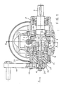
- the drive unit shown comprises a multi-part housing 1, on which a drive motor 2 is flanged, which drives a worm shaft 3, which is in engagement with a worm ring 4.
- the worm ring 4 has a conical inner bore which engages with a conical ring 5 of a slip clutch.
- the conical ring 5 sits via a feather key 6feder (Fig. 3) firmly on an output shaft 6, which is mounted sealed in the housing 1.
- the output shaft 6 is supported on both sides in the housing 1 via roller bearings 6lager.
- a thrust washer 7, which is axially movable with respect to the output shaft 6, is pressed against the worm ring 4 via a plate spring assembly 8.
- the slip torque is via a nut 9, which is screwed onto the output shaft 6 and provided on the outer circumference with axial grooves for its adjustment, and a ring 10 arranged between the nut 9 and the plate spring assembly 8 and the prestressing of the plate spring assembly 8 caused thereby, which on the Thrust washer 7 and thus acts on the friction surface between the worm ring 4 and ring 5, is set.
- the nut 9 is held in place in particular by a locking pin which can be snap-locked on the circumference of the nut and is spring-biased in the direction of the nut 9 and which can be locked in operation in the non-engagement position of the nut 9 by means of a locking device which can be actuated outside the housing 1.
- the outwardly sealed housing 1 is closed at one end by an insert 11 which has a bore coaxial with the output shaft 6.
- This bore is threaded in its central section and expanded in its section on the inside of the housing. It receives a screw 12 which extends out of the insert 11 in a sealed manner and extends into the enlarged section of the bore.
- the screw 12 is engaged with a plunger 13 which extends coaxially through a bore 14 in the adjacent end of the abrasion shaft 6 and into a slot 15 which extends radially through the output shaft 6.
- a cross wedge 16 is axially displaceable and arranged through the slot 15.
- the transverse wedge 16 is in engagement with the thrust washer 7, on the one hand, and also with the facing end of the tappet 13, on the other hand, via its ends projecting beyond the diameter of the output shaft 6.
- the plunger 13 is provided with two collars 17 which receive an axial deep groove ball bearing 18 between them, by which the bearing ring with a larger diameter is received and guided by the enlarged section of the bore of the insert 11.
- the end of the screw 12 protruding from the insert 11 is connected to a lever 19 which can be pivoted by a predetermined angular position, as a result of which the screw 12 is rotated inwards from its initial position shown in FIG. 1.
- the plunger 13 and thus the transverse wedge 16 are axially displaced, whereby the slip clutch is relieved.
- the output shaft 6 is thus freely movable.
- the screw 12 is provided with a bore which receives the facing end of the plunger 13 in an enlarged section on the inside of the housing and is tightly closed to the outside by a screw 20.
- One or more spacers 21 can be arranged between the screw 20 and the facing end of the plunger 13.
- the insert 11 can have locking recesses 22 on the outside at predetermined locations, into which a spring-preloaded ball 24 carried by a screw 23 can snap.
- the screw 23 is received by the lever 19.
- the insert 11 can have stops 25, which limit the pivoting movement of the lever 19 at an angle.
Landscapes
- Engineering & Computer Science (AREA)
- Mechanical Engineering (AREA)
- General Engineering & Computer Science (AREA)
- Gear Transmission (AREA)
Applications Claiming Priority (2)
| Application Number | Priority Date | Filing Date | Title |
|---|---|---|---|
| DE8629599U | 1986-11-05 | ||
| DE19868629599 DE8629599U1 (de) | 1986-11-05 | 1986-11-05 | Schneckengetriebe |
Publications (2)
| Publication Number | Publication Date |
|---|---|
| EP0266531A2 true EP0266531A2 (fr) | 1988-05-11 |
| EP0266531A3 EP0266531A3 (fr) | 1990-02-28 |
Family
ID=6799953
Family Applications (1)
| Application Number | Title | Priority Date | Filing Date |
|---|---|---|---|
| EP87113743A Withdrawn EP0266531A3 (fr) | 1986-11-05 | 1987-09-19 | Equipement moteur |
Country Status (2)
| Country | Link |
|---|---|
| EP (1) | EP0266531A3 (fr) |
| DE (1) | DE8629599U1 (fr) |
Cited By (4)
| Publication number | Priority date | Publication date | Assignee | Title |
|---|---|---|---|---|
| EP0446655A1 (fr) * | 1990-03-16 | 1991-09-18 | W.u.H. Neukirchen GmbH & Co. KG | Transmission à vis sans fin à blocage automatique pour un entraînement de porte à haut régime |
| EP0657340A1 (fr) * | 1993-12-07 | 1995-06-14 | Koyo Seiko Co., Ltd. | Direction assistée |
| WO2006036514A1 (fr) * | 2004-09-23 | 2006-04-06 | Mtd Products Inc | Transmission pour une tondeuse poussee |
| DE19946484B4 (de) * | 1998-10-12 | 2010-11-25 | Magna Steyr Fuel Systems Gesmbh | Antriebsvorrichtung für eine Verschlusseinrichtung eines Fahrzeugtank-Einfüllstutzens |
Family Cites Families (5)
| Publication number | Priority date | Publication date | Assignee | Title |
|---|---|---|---|---|
| DE476034C (de) * | 1925-12-11 | 1929-05-10 | Wilhelm Todt & Sohn | Reibungskupplung |
| DE2522293A1 (de) * | 1975-05-20 | 1976-12-02 | Tornado Elektromotorfab Gmbh | Vorrichtung zum einkuppeln und entkuppeln einer abtriebswelle eines schnekkengetriebes |
| DE2842814A1 (de) * | 1978-09-30 | 1980-04-10 | Delwing Dieter | Mit motor oder mit hand angetriebene, ggf. fernsteuerbare ankerwinde |
| DE3123284C2 (de) * | 1981-06-12 | 1985-06-05 | Rhein-Getriebe Gmbh, 4005 Meerbusch | Rutschkupplung |
| IT1204113B (it) * | 1986-01-23 | 1989-03-01 | S T M Spa | Limitatore di coppia per motoriduttori |
-
1986
- 1986-11-05 DE DE19868629599 patent/DE8629599U1/de not_active Expired
-
1987
- 1987-09-19 EP EP87113743A patent/EP0266531A3/fr not_active Withdrawn
Cited By (5)
| Publication number | Priority date | Publication date | Assignee | Title |
|---|---|---|---|---|
| EP0446655A1 (fr) * | 1990-03-16 | 1991-09-18 | W.u.H. Neukirchen GmbH & Co. KG | Transmission à vis sans fin à blocage automatique pour un entraînement de porte à haut régime |
| EP0657340A1 (fr) * | 1993-12-07 | 1995-06-14 | Koyo Seiko Co., Ltd. | Direction assistée |
| US5482128A (en) * | 1993-12-07 | 1996-01-09 | Koyo Seiko Co., Ltd. | Power steering apparatus |
| DE19946484B4 (de) * | 1998-10-12 | 2010-11-25 | Magna Steyr Fuel Systems Gesmbh | Antriebsvorrichtung für eine Verschlusseinrichtung eines Fahrzeugtank-Einfüllstutzens |
| WO2006036514A1 (fr) * | 2004-09-23 | 2006-04-06 | Mtd Products Inc | Transmission pour une tondeuse poussee |
Also Published As
| Publication number | Publication date |
|---|---|
| EP0266531A3 (fr) | 1990-02-28 |
| DE8629599U1 (de) | 1987-01-02 |
Similar Documents
| Publication | Publication Date | Title |
|---|---|---|
| DE2104546C3 (de) | Stufenloses Keilriemengetriebe | |
| DE2734630C2 (de) | Zweisträngiges stufenlos einstellbares Kegelscheibenumschlingungsgetriebe mit gleichmäßiger Lastverteilung | |
| DE2522446C3 (de) | Sicherheitsrutschkupplung für Handbohrmaschine | |
| DE2301448B2 (fr) | ||
| DE2613065C3 (de) | Automatische Kupplungsvorrichtung für ein Handrad | |
| DE69014491T2 (de) | Stufenloses Getriebe. | |
| DE1276498B (de) | Vorrichtung zum Bewegen von Schiebefenstern, insbesondere in Kraftfahrzeugtueren miteinem Kurbelantrieb und einem elektromotorischen, umschaltbaren Antrieb | |
| DE2842814A1 (de) | Mit motor oder mit hand angetriebene, ggf. fernsteuerbare ankerwinde | |
| DE4118941C2 (de) | Nabe/Wellenverbindung | |
| DE3502283C2 (fr) | ||
| EP0266531A2 (fr) | Equipement moteur | |
| DE2322196C3 (de) | Einstellvorrichtung für die Zugmittel-Spannanordnung eines Kegelscheibenumschlingungsgetriebes | |
| DE4441820B4 (de) | Bohr- und/oder Schlaghammer | |
| DE2629279B2 (de) | Stufenlos regelbares Keilriemengetriebe | |
| DE3331421A1 (de) | Uebersetzungsverhaeltnis-variationseinrichtung | |
| DE19757500C1 (de) | Reibungsschlupfkupplung für elektrische Antriebe von Hebezeugen | |
| DE4425272C2 (de) | Hubwerk | |
| DE102004052124B3 (de) | Motorisch antreibbares Werkzeuggerät mit einer Spindelarretiereinrichtung | |
| DE3009853B1 (de) | Fliehkraftschaltkupplung | |
| EP1475346B1 (fr) | Appareil de levage | |
| EP1003650A1 (fr) | Sortie de pont avant d'une transmission automatique | |
| DE3004663C2 (de) | Hobeltriebwerk | |
| DE3432419C2 (de) | Getriebe mit Notabschaltung | |
| DE2263229C3 (de) | Stufenlos einstellbares Kegelscheibenumschlingungsgetriebe mit dreh- | |
| DE19803531A1 (de) | Antriebsvorrichtung für ein verstellbares Teil eines Fahrzeuges |
Legal Events
| Date | Code | Title | Description |
|---|---|---|---|
| PUAI | Public reference made under article 153(3) epc to a published international application that has entered the european phase |
Free format text: ORIGINAL CODE: 0009012 |
|
| AK | Designated contracting states |
Kind code of ref document: A2 Designated state(s): DE FR IT |
|
| PUAL | Search report despatched |
Free format text: ORIGINAL CODE: 0009013 |
|
| AK | Designated contracting states |
Kind code of ref document: A3 Designated state(s): DE FR IT |
|
| STAA | Information on the status of an ep patent application or granted ep patent |
Free format text: STATUS: THE APPLICATION HAS BEEN WITHDRAWN |
|
| 18W | Application withdrawn |
Withdrawal date: 19900614 |
|
| RIN1 | Information on inventor provided before grant (corrected) |
Inventor name: BANNIER, GEORG |