EP0266565A1 - Kettenspanner - Google Patents
Kettenspanner Download PDFInfo
- Publication number
- EP0266565A1 EP0266565A1 EP87114459A EP87114459A EP0266565A1 EP 0266565 A1 EP0266565 A1 EP 0266565A1 EP 87114459 A EP87114459 A EP 87114459A EP 87114459 A EP87114459 A EP 87114459A EP 0266565 A1 EP0266565 A1 EP 0266565A1
- Authority
- EP
- European Patent Office
- Prior art keywords
- stop
- stop ring
- housing
- damping piston
- chain tensioner
- Prior art date
- Legal status (The legal status is an assumption and is not a legal conclusion. Google has not performed a legal analysis and makes no representation as to the accuracy of the status listed.)
- Granted
Links
Images

Classifications
-
- F—MECHANICAL ENGINEERING; LIGHTING; HEATING; WEAPONS; BLASTING
- F16—ENGINEERING ELEMENTS AND UNITS; GENERAL MEASURES FOR PRODUCING AND MAINTAINING EFFECTIVE FUNCTIONING OF MACHINES OR INSTALLATIONS; THERMAL INSULATION IN GENERAL
- F16H—GEARING
- F16H7/00—Gearings for conveying rotary motion by endless flexible members
- F16H7/08—Means for varying tension of belts, ropes or chains
- F16H7/0848—Means for varying tension of belts, ropes or chains with means for impeding reverse motion
-
- F—MECHANICAL ENGINEERING; LIGHTING; HEATING; WEAPONS; BLASTING
- F16—ENGINEERING ELEMENTS AND UNITS; GENERAL MEASURES FOR PRODUCING AND MAINTAINING EFFECTIVE FUNCTIONING OF MACHINES OR INSTALLATIONS; THERMAL INSULATION IN GENERAL
- F16H—GEARING
- F16H7/00—Gearings for conveying rotary motion by endless flexible members
- F16H7/08—Means for varying tension of belts, ropes or chains
- F16H2007/0802—Actuators for final output members
- F16H2007/0806—Compression coil springs
-
- F—MECHANICAL ENGINEERING; LIGHTING; HEATING; WEAPONS; BLASTING
- F16—ENGINEERING ELEMENTS AND UNITS; GENERAL MEASURES FOR PRODUCING AND MAINTAINING EFFECTIVE FUNCTIONING OF MACHINES OR INSTALLATIONS; THERMAL INSULATION IN GENERAL
- F16H—GEARING
- F16H7/00—Gearings for conveying rotary motion by endless flexible members
- F16H7/08—Means for varying tension of belts, ropes or chains
- F16H2007/0802—Actuators for final output members
- F16H2007/0812—Fluid pressure
-
- F—MECHANICAL ENGINEERING; LIGHTING; HEATING; WEAPONS; BLASTING
- F16—ENGINEERING ELEMENTS AND UNITS; GENERAL MEASURES FOR PRODUCING AND MAINTAINING EFFECTIVE FUNCTIONING OF MACHINES OR INSTALLATIONS; THERMAL INSULATION IN GENERAL
- F16H—GEARING
- F16H7/00—Gearings for conveying rotary motion by endless flexible members
- F16H7/08—Means for varying tension of belts, ropes or chains
- F16H7/0848—Means for varying tension of belts, ropes or chains with means for impeding reverse motion
- F16H2007/0853—Ratchets
- F16H2007/0855—Ratchets comprising a clip member engaging with the rack teeth
-
- F—MECHANICAL ENGINEERING; LIGHTING; HEATING; WEAPONS; BLASTING
- F16—ENGINEERING ELEMENTS AND UNITS; GENERAL MEASURES FOR PRODUCING AND MAINTAINING EFFECTIVE FUNCTIONING OF MACHINES OR INSTALLATIONS; THERMAL INSULATION IN GENERAL
- F16H—GEARING
- F16H7/00—Gearings for conveying rotary motion by endless flexible members
- F16H7/08—Means for varying tension of belts, ropes or chains
- F16H7/0848—Means for varying tension of belts, ropes or chains with means for impeding reverse motion
- F16H2007/0859—Check valves
-
- F—MECHANICAL ENGINEERING; LIGHTING; HEATING; WEAPONS; BLASTING
- F16—ENGINEERING ELEMENTS AND UNITS; GENERAL MEASURES FOR PRODUCING AND MAINTAINING EFFECTIVE FUNCTIONING OF MACHINES OR INSTALLATIONS; THERMAL INSULATION IN GENERAL
- F16H—GEARING
- F16H7/00—Gearings for conveying rotary motion by endless flexible members
- F16H7/08—Means for varying tension of belts, ropes or chains
- F16H2007/0889—Path of movement of the finally actuated member
- F16H2007/0891—Linear path
-
- F—MECHANICAL ENGINEERING; LIGHTING; HEATING; WEAPONS; BLASTING
- F16—ENGINEERING ELEMENTS AND UNITS; GENERAL MEASURES FOR PRODUCING AND MAINTAINING EFFECTIVE FUNCTIONING OF MACHINES OR INSTALLATIONS; THERMAL INSULATION IN GENERAL
- F16H—GEARING
- F16H7/00—Gearings for conveying rotary motion by endless flexible members
- F16H7/08—Means for varying tension of belts, ropes or chains
- F16H7/0829—Means for varying tension of belts, ropes or chains with vibration damping means
Definitions
- the invention relates to a chain tensioner with a damping piston guided in a housing, which is axially acted upon by a spring means in the chain tensioning direction, and with a radially resilient stop ring, which are assigned to recesses in the housing and the damping piston, and which allows a return movement of the damping piston against the chain tensioning direction , but their stroke is limited.
- Such chain tensioners are used for example in a drive chain of camshafts of an internal combustion engine.
- Such a chain tensioner is described in DE-OS 16 50 620.
- a cap nut In the chain tensioner according to DE-OS 16 50 620, a cap nut must be attached in a sealed manner for mounting the damping piston on the housing, on which the damping piston is supported by a compression spring.
- the stop ring When assembling the chain tensioner, the stop ring does not necessarily come into the correct starting position. The assembly of the chain tensioner itself and its installation associated with the chain is problematic.
- the object of the invention is to propose a chain tensioner of the type mentioned, the Installation possibility is so simplified that the damping piston and the stop ring from the open side of the housing, in which the damping piston acts on the chain, can be inserted and that the stop ring when inserting the piston into the correct output assignment between the housing and the damping piston reached.
- the housing has a receiving groove and the damping piston has an insertion edge for the stop ring, and when the damping piston is inserted into the housing, the insertion edge takes the stop ring with it until it snaps radially into the receiving groove that a locking groove for the damping piston the stop ring is formed, which is limited on the one hand by a stop edge and on the other hand by a stop ramp, the stop ramp fitting under the stop ring snapped into the receiving groove that the stop edge pushes the stop ring out of the receiving groove into a latching groove of the housing under the force of the spring means and that at the end of a return stroke the stop ring lying in the locking groove strikes the stop ramp.
- the housing can be made in one piece, a blind hole being sufficient to accommodate the spring means and the damping piston. This makes assembling the chain tensioner easy. In addition, there are no sealing problems on the housing. This is particularly advantageous if the chain tensioner is a hydraulic chain tensioner, the damping piston being acted upon by oil pressure.
- the stop ramp hits the stop ring at the end of the return stroke and thus limits the return of the piston.
- a special case is present, for example, if, when the direction of rotation of the chain is reversed, its empty run becomes a work run. This is the case with an engine of a motor vehicle, for example, when the vehicle is parked in the uphill direction with the forward gear engaged or in the downhill direction with the reverse gear engaged.
- the limitation of the return of the piston by the stop ring and the stop ramp ensures that the piston does not go back so far that the chain jumps over the next time the engine is started.
- the possible return stroke is greater than or equal to the damping stroke, taking into account the temperature-related elongation of the chain.
- a plurality of locking grooves are provided on the housing, the Stop edge of the piston pushes the stop ring in the course of an elongation of the chain into the next locking groove under the action of the spring means.
- the stop ring acts in the same way as a stop for the stop edge or the stop ramp of the locking groove of the piston.
- the possible return stroke is smaller than the distance between the locking grooves. There is even chain tension throughout the chain tensioning range.
- a mounting ring is snapped into a groove of the damping piston provided with a bevel and a locking surface adjoining this.
- the mounting ring can be slid onto the locking surface using a tool that can be inserted into a gap between the housing and the damping piston, wherein it engages in a groove in the housing and blocks movement of the piston relative to the housing.
- the chain tensioner is easy to install in the locked position. If the chain should then act in the operating position of the damping piston, then the piston must be pressed manually against the force of the spring means, the mounting ring snapping back into the groove from the latching surface. The blocking position is released so that the stop ring is pushed into the - first - locking groove under the force of the spring means.
- Figures 2 to 6 are reduced compared to Figure 1.
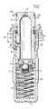
- a one-piece housing (1) has a guide bore (2) that is open on one side.
- a hollow damping piston (3) is inserted into this.
- a check valve (5) is arranged on the side of the damping piston (3) facing the bottom (4) of the housing (1).
- a compression spring (6) acting on the piston (3) lies between the base (4) and the check valve (5).
- An opening (7) is provided on the side of the piston (3) and communicates with an oil pressure connection (8) of the housing (1).
- An opening (9) at the head of the piston (3) is used for ventilation.
- a receiving groove (10), three or, if necessary, several identical locking grooves (11, 12, 13) and an insertion bevel (14) are formed side by side from the inside.
- the diameter of the receiving groove (10) is larger than that of the locking groove (11).
- the receiving groove (10) has a bevel (15) towards the locking groove (11). With corresponding bevels (16, 17) the locking grooves (11,12).
- a locking groove (18) is formed on the outer circumference of the piston (3) and is delimited on the one hand by a stop edge (19) and on the other hand by a stop ramp (20).
- the stop ramp (20) has a locking surface (21), a stop edge (22) and a passage surface (23).
- An insertion groove (24) with an insertion edge (25) adjoins the stop ramp (20).
- the outer diameter of the stop edge (19) and the insertion edge (25) correspond to the outer diameter of the piston (3).
- the diameter of the passage surface (23) is smaller.
- a resilient stop ring (26) is associated with the aforementioned circumferential grooves or grooves in the housing (1) and the piston (3).
- the piston (3) After inserting the compression spring (6) into the housing (1), the piston (3) is inserted, in whose insertion groove (24) the stop ring (26) is placed.
- the mounting ring (30) lies resiliently in the groove (29) and rests resiliently on the groove base.
- the stop ring (26) reaches the insertion bevel (14), which presses it against the spring force into the insertion groove (24).
- the insertion edge (25) presses the stop ring (26) under the locking grooves (13, 12, 11) until it reaches the receiving groove (10).
- the stop ring (26) expands under its spring force, so that it lies against the bottom of the receiving groove (10).
- the depth of the receiving groove (10) is smaller than the cross section of the stop ring (26), so that the in the receiving groove (10) horizontal stop ring (26) forms the innermost stop for manual insertion in the direction of arrow (E) (cf. FIG. 2).
- the mounting ring (30) lies below the locking groove (13).
- the assembly ring (30) is held in this position with a tool inserted through the gap (31) between the piston (3) and the housing (1) and the piston (3) is released.
- the piston (3) then moves in the direction of the arrow (B), the locking surface (27) sliding under the mounting ring (30) via the bevel (28) and the latter against its spring force into the Latch groove (13) presses.
- the blocking position of the piston (3) is then reached (cf. FIG. 3).
- the chain tensioner is mounted on the unit, for example an engine, the chain of which is to be tensioned.
- the stop ring (26) has no effect. It stands above the passage area (23).
- the damping piston (3) is pressed manually against the direction of the arrow (B), so that the mounting ring (30) is detached from the latching surface (27). under its spring force slides over the slope (28) into the groove (29). The stop ring (26) does not prevent this since its distance from the insertion edge (25) is sufficiently large.
- the piston (3) now moves in the direction of arrow (A) under the action of the compression spring (6) in the chain tensioning direction.
- the stop edge (19) meets the stop ring (26) and pushes it over the slope (15) in the direction of the locking groove (11) (see FIG. 4).
- the locking groove (18) is sufficiently deep so as not to hinder the compression of the stop ring (26).
- the stop ring (26) then snaps into the first locking groove (11). This position is the beginning of the Chain tensioning area.
- the chain is now taut.
- a high pressure is built up via the non-return valve (5) in the housing (1) between the latter and the piston (3) in the space (32) via the oil pressure connection (8), which is under engine oil pressure in the example.
- This maximum return stroke (H) is determined by the distance of the stop edge (19) from the stop edge (22) and the diameter of the circular cross section of the stop ring (26). The maximum return stroke is 2 mm, for example.
- the limitation of the return stroke (H) prevents the chain from jumping over teeth of the gearwheels driven by it in the event of sudden loads. It is also favorable that the stop ring (26) only acts as a stop with regard to the tensioning and damping of the chain and its spring property only serves to bring it into the appropriate position in each case.
- the Limitation of the maximum return stroke (H) by the stop ring (26) is effective, for example, if shortly after starting the engine no sufficient oil pressure has built up in the room (32), or when the engine is switched off, the chain's empty strand, which the chain tensioner engages , is charged.
- the piston (3) is moved further in the direction of the arrow (K) (see FIG. 5) under the action of the compression spring (6) or the oil pressure in the space (32) , wherein its stop edge (19) moves the stop ring (26) over the slope (16) of the locking groove (11) into the next locking groove (12).
- the distance between the locking grooves (11, 12, 13) is greater than the maximum return stroke (H).
- the useful stroke (N) of the piston (3) (cf. FIG. 1) that determines the chain tensioning range is, for example, 23 mm.
Landscapes
- Engineering & Computer Science (AREA)
- General Engineering & Computer Science (AREA)
- Mechanical Engineering (AREA)
- Devices For Conveying Motion By Means Of Endless Flexible Members (AREA)
Abstract
Description
- Die Erfindung betrifft einen Kettenspanner mit einem in einem Gehäuse geführten Dämpfungskolben, der von einem Federmittel in Kettenspannrichtung axial beaufschlagt ist, und mit einem radial federnden Anschlagring, dem Ausnehmungen des Gehäuses und des Dämpfungskolbens zugeordnet sind und der eine Rücklaufbewegung des Dämpfungskolbens entgegen der Kettenspannrichtung zwar zuläßt, jedoch deren Hub begrenzt.
- Derartige Kettenspanner werden beispielsweise bei einer Antriebskette von Nockenwellen eines Verbrennungsmotors verwendet. Ein derartiger Kettenspanner ist in der DE-OS 16 50 620 beschrieben.
- Bei dem Kettenspanner nach der DE-OS 16 50 620 ist zur Montage des Dämpfungskolbens am Gehäuse eine Hutmutter abgedichtet anzubringen, an der sich der Dämpfungskolben über eine Druckfeder abstützt. Der Anschlagring kommt beim Zusammenbau des Kettenspanners nicht zwangsläufig in die richtige Ausgangsstellung. Der Zusammenbau des Kettenspanners selbst und sein der Kette zugeordneter Einbau ist problematisch.
- Aufgabe der Erfindung ist es, einen Kettenspanner der eingangs genannten Art vorzuschlagen, dessen Montagemöglichkeit so vereinfacht ist, daß der Dämpfungskolben und der Anschlagring von der offenen Seite des Gehäuses her, bei der der Dämpfungskolben auf die Kette wirkt, einschiebbar ist und daß der Anschlagring beim Einschieben des Kolbens in die richtige Ausgangs-Zuordnung zwischen dem Gehäuse und dem Dämpfungskolben gelangt.
- Erfindungsgemäß ist obige Aufgabe dadurch gelöst, daß das Gehäuse eine Aufnahmenut und der Dämpfungskolben einen Einschubrand für den Anschlagring aufweisen, wobei beim Einschieben des Dämpfungskolbens in das Gehäuse der Einschubrand den Anschlagring mitnimmt, bis dieser in die Aufnahmenut radial einschnappt, daß am Dämpfungskolben eine Sperrnut für den Anschlagring ausgebildet ist, die einerseits von einem Anschlagrand und andererseits von einer Anschlagrampe begrenzt ist, wobei die Anschlagrampe unter dem in die Aufnahmenut eingeschnappten Anschlagring hindurchpaßt, daß der Anschlagrand unter der Kraft des Federmittels den Anschlagring aus der Aufnahmenut in eine Rastrille des Gehäuses schiebt und daß am Ende eines Rücklaufhubes der in der Rastrille liegende Anschlagring an der Anschlagrampe anschlägt.
- Durch diese Gestaltung ist es möglich, den Dämpfungskolben und den Anschlagring von der offenen Seite des Gehäuses, bei der der Dämpfungskolben auf die Kette wirkt, in das Gehäuse einzuschieben. Dementsprechend kann das Gehäuse einteilig hergestellt sein, wobei zur Aufnahme des Federmittels und des Dämpfungskolbens ein Sackloch genügt. Der Zusammenbau des Kettenspanners ist dadurch einfach. Außerdem entfallen Dichtungsprobleme am Gehäuse. Dies ist insbesondere dann vorteilhaft, wenn der Kettenspanner ein hydraulischer Kettenspanner ist, wobei der Dämpfungskolben durch Öldruck beaufschlagt ist.
- Beim Zusammenbau des Kettenspanners wird mittels des Einschubrandes der Anschlagring mit in das Gehäuse eingeschoben. Er spreizt sich in der Aufnahmenut radial federnd auf. Unter der Kraft des Federmittels wird danach die Anschlagrampe des Kolbens unter dem Anschlagring hindurchgeschoben. Dieser wird anschließend vom Anschlagrand der Sperrnut in die Rastrille geschoben. In dieser Stellung ist die Ausgangsstellung für den Ketten-Spannbereich erreicht.
- Wirkt von der Kette eine Stoßbelastung auf den Kolben, dann führt dies zu einem Rücklauf des Kolbens. Im Normalfall, wenn der Kolben unter Öldruck steht, ist der Rücklauf gedämpft und durch die Dämpfungsrate des Öldruck- Kolben- Systems begrenzt. Der Rücklauf endet, bevor die Anschlagrampe an dem Anschlagring anstößt (Dämpfungshub).
- In Sonderfällen, in denen sich der Öldruck nicht oder noch nicht aufgebaut hat oder nicht mehr besteht und eine Belastung der Kette vorliegt, schlägt die Anschlagrampe am En de des Rücklaufhubs am Anschlagring an und begrenzt damit den Rücklauf des Kolbens. Ein derartiger Sonderfall liegt beispielsweise vor, wenn bei einer Umkehr der Umlaufrichtung der Kette deren Leertrum zum Arbeitstrum wird. Dies bei einem Motor eines Kraftfahrzeugs beispielsweise der Fall, wenn das Fahrzeug in Fahrtrichtung bergauf mit eingelegtem Vorwärtsgang oder in Fahrtrichtung bergab mit eingelegtem Rückwärtsgang abgestellt wird. Die Begrenzung des Rücklaufs des Kolbens durch den Anschlagring und die Anschlagrampe stellt sicher, daß der Kolben nicht soweit zurückgeht, daß die Kette bei einem folgenden Anlassen des Motors überspringt. Der mögliche Rücklaufhub ist größer als der oder gleich dem Dämpfungshub unter Berücksichtigung der temperaturbedingten Längung der Kette.
- In bevorzugter Ausgestaltung der Erfindung sind am Gehäuse mehrere Rastrillen vorgesehen, wobei der Anschlagrand des Kolbens unter der Wirkung des Federmittels den Anschlagring im Zuge einer Längung der Kette in die jeweils nächste Rastrille schiebt. Es ist dadurch ein großer Ketten-Spannbereich bei entsprechend proportional kleinerem Dämpfungshub zu erreichen. In jeder Rastrille wirkt der Anschlagring in gleicher Weise als Anschlag für den Anschlagrand bzw. die Anschlagrampe der Sperrnut des Kolbens. Der mögliche Rücklaufhub ist kleiner als der Abstand der Rastrillen. Im gesamten Ketten-Spannbereich ergibt sich eine gleichmäßige Kettenspannung.
- In einer Weiterbildung der Erfindung ist ein Montagering in eine mit einer Schräge und einer an diese anschließenden Rastfläche versehenen Nut des Dämpfungskolbens eingeschnappt. Der Montagering ist unter Verwendung eines in einen Spalt zwischen dem Gehäuse und dem Dämpfungskolben einsteckbaren Werkzeugs über eine Schräge auf die Rastfläche aufschiebbar, wobei er in eine Rille des Gehäuses greift und eine Bewegung des Kolbens gegenüber dem Gehäuse blockiert. In der Blockierstellung ist der Kettenspanner einfach zu montieren. Soll dann in Betriebsstellung der Dämpfungskolben die Kette beaufschlagen, dann ist der Kolben manuell entgegen der Kraft des Federmittels zu drücken, wobei der Montagering von der Rastfläche in die Nut zurückschnappt. Die Blockierstellung ist dadurch aufgehoben, so daß unter der Kraft des Federmittels der Anschlagring in die - erste - Rastrille geschoben wird.
- Weitere vorteilhafte Ausgestaltungen der Erfindung ergeben sich aus Unteransprüchen und der folgenden Beschreibung eines Ausführungsbeispiels. In der Zeichnung zeigen:
- Figur 1 einen Kettenspanner im Schnitt, wobei der Dämpfungskolben in der äußersten Raststellung steht,
- Figur 2 eine Teilansicht des Kettenspanners, wobei der Dämpfungskolben in der innersten Anschlagstellung steht,
- Figur 3 eine Teilansicht des Kettenspanners, wobei der Dämpfungskolben in Montagestellung blockiert ist,
- Figur 4 eine Teilansicht des Kettenspanners, wobei der Dämpfungskolben sich in die innerste Raststellung bewegt,
- Figur 5 eine Teilansicht des Kettenspanners, wobei der Dämpfungskolben in seiner innersten Raststellung steht und
- Figur 6 eine Teilansicht des Kettenspanners, wobei aus der Stellung nach Figur 5 von der Kette eine Stoßbelastung auf den Dämpfungskolben ausgeübt ist.
- Die Figuren 2 bis 6 sind gegenüber Figur 1 verkleinert.
- Ein einteiliges Gehäuse(1) weist eine einseitig offene Führungsbohrung(2) auf. In diese ist ein hohler Dämpfungskolben(3) eingesetzt. An der dem Boden(4) des Gehäuses(1) zugewandten Seite des Dämpfungskolbens(3) ist ein Rückschlagventil(5) angeordnet. Zwischen dem Boden(4) und dem Rückschlagventil(5) liegt eine auf den Kolben(3) wirkende Druckfeder(6). Seitlich am Kolben(3) ist eine Öffnung(7) vorgesehen, die mit einem Öldruckanschluß(8) des Gehäuses(1) in Verbindung steht. Eine Öffnung(9) am Kopf des Kolbens(3) dient der Entlüftung.
- Am Innenumfang des Gehäuses(1) sind von innen nach außen nebeneinander eine Aufnahmenut(1 0), drei oder im Bedarfsfall mehrere gleiche Rastrillen(11,12,13), sowie eine Einführschräge(14) ausgebildet. Der Durchmesser der Aufnahmenut(10) ist größer als der der Rastrille(11). Die Aufnahmenut(10) weist zur Rastrille(11) hin eine Schräge(15) auf. Mit entsprechenden Schrägen(16,17) sind die Rastrillen(11,12) versehen.
- Am Außenumfang des Kolbens(3) ist eine Sperrnut(18) ausgebildet, die einerseits von einem Anschlagrand(19) und andererseits von einer Anschlagrampe(20) begrenzt ist. Die Anschlagrampe(20) weist eine Sperrfläche(21), eine Anschlagkante(22) und eine Durchgangsfläche(23) auf. An die Anschlagrampe(20) schließt sich eine Einschubnut(24) mit einem Einschubrand(25) an. Der äußere Durchmesser des Anschlagrandes(19) und des Einschubrandes(25) entsprechen dem Außendurchmesser des Kolbens(3). Der Durchmesser der Durchgangsfläche(23) ist kleiner. Den genannten, umlaufenden Nuten bzw. Rillen des Gehäuses(1) und des Kolbens(3) ist ein federnder Anschlagring(26) zugeordnet.
- Außen an dem Kolben(3) ist eine mit einer Rastfläche(27) und einer Schräge(28) versehene Nut(29) ausgebildet, die einem Montagering(30) zugeordnet ist.
- Der Zusammenbau des beschriebenen Kettenspanners geschieht etwa folgendermaßen:
- Nach dem Einsetzen der Druckfeder(6) in das Gehäuse(1) wird der Kolben(3) eingeschoben, in dessen Einschubnut(24) der Anschlagring(26) gelegt ist. In der Nut(29) liegt dabei der Montagering(30), der federnd am Nutgrund anliegt. Beim Einschieben des Kolbens(3) gelangt der Anschlagring(26) an die Einführschräge(14), die diesen entgegen seiner Federkraft in die Einschubnut(24) drückt. Beim weiteren Einschieben des Kolbens(3) drückt der Einschubrand(25) den Anschlagring(26) unter den Rastrillen(13,12,11) hindurch, bis er in die Aufnahmenut(10) gelangt. In der Aufnahmenut(10) spreizt sich der Anschlagring(26) unter seiner Federkraft auf, so daß er am Grund der Aufnahmenut(10) anliegt. Die Tiefe der Aufnahmenut(10) ist kleiner als der Querschnitt des Anschlagrings(26), so daß der in der Aufnahmenut(10) liegende Anschlagring(26) den innersten Anschlag für das manuelle Einschieben in Richtung des Pfeiles(E) bildet (vgl. Figur 2). Der Montagering(30) liegt dabei unterhalb der Rastrille(13).
- Danach wird mit einem durch den Spalt(31) zwischen dem Kolben(3) und dem Gehäuse(1) eingesteckten Werkzeug der Montagering(30) in dieser Stellung gehalten und der Kolben(3) wird freigelassen. Unter der Wirkung der Druckfeder(6) verschiebt sich dann der Kolben(3) in Richtung des Pfeiles(B), wobei über die Schräge(28) die Rastfläche(27) unter den Montagering(30) gleitet und diesen entgegen seiner Federkraft in die Rastrille(13) drückt. Es ist dann die Blockierstellung des Kolbens(3) erreicht (vgl. Figur 3). In der Blockierstellung wird der Kettenspanner an dem Aggregat, beispielsweise Motor, dessen Kette zu spannen ist, montiert. In dieser Blockierstellung ist der Anschlagring(26) wirkungslos. Er steht über der Durchgangsfläche(23).
- Nach der Montage der Kette und gegebenenfalls eines zwischen dem Kolben(3) und der Kette vorgesehenen Übertragungsgliedes wird entgegen der Richtung des Pfeiles(B) manuell auf den Dämpfungskolben(3) gedrückt, so daß der Montagering(30) von der Rastfläche(27) unter seiner Federkraft über die Schräge(28) in die Nut(29) gleitet. Der Anschlagring(26) verhindert dies nicht, da sein Abstand zum Einschubrand(25) ausreichend groß ist.
- Der Kolben(3) bewegt sich nun in Richtung des Pfeiles(A) unter der Wirkung der Druckfeder(6) in Kettenspannrichtung. Der Anschlagrand(19) trifft dabei auf den Anschlagring(26) und schiebt diesen über die Schräge(15) in Richtung der Rastrille(11) (vgl. Figur 4). Die Sperrnut(18) ist hinreichend tief, um dabei das Zusammendrücken des Anschlagrings(26) nicht zu behindern. Der Anschlagring(26) schnappt dann in die erste Rastrille(11). Diese Stellung ist der Beginn des Ketten-Spannbereiches. Die Kette ist jetzt gespannt.
- Die Arbeitsweise im Betrieb ist etwa folgende:
- Über den Öldruckanschluß(8), der im Beispielsfalle unter Motoröldruck steht, wird über das Rückschlagventil(5) im Gehäuse(1) zwischen diesem und dem Kolben(3) im Raum(32) ein Hochdruck aufgebaut.
- Bei einer schlagartigen Belastung der Kette wirkt auf den Kolben(3) eine Kraft in Richtung des Pfeiles(S) (vgl. Figur 6). Dies führt zu einer Rücklaufbewegung des Kolbens(3) entgegen der Kraftrichtung der Druckfeder(6). Die Rücklaufbewegung ist durch den Öldruck im Raum(32) des Gehäuses(1) gedämpft. Bei der Rücklaufbewegung gelangt die Sperrfläche(21) unter den in der Rastrille(11) liegenden Anschlagring(26). Sie verhindert, daß der Anschlagring(26) zusammengedrückt wird und gewährleistet, daß er am Grund der Rastrille(11) verbleibt.
- Reicht der Öldruck im Raum(32) nicht aus um den Kolben(3) bei Belastung zum Stillstand zu bringen, dann trifft die Anschlagkante(22) auf den Anschlagring(26). Dadurch ist die Rücklaufbewegung des Kolbens(3) in Richtung des Pfeiles(S) begrenzt. Dieser maximale Rücklaufhub(H) ist durch den Abstand des Anschlagrandes(19) von der Anschlagkante(22) und den Durchmesser des kreisförmigen Querschnittes des Anschlagrings(26) bestimmt. Der maximale Rücklaufhub beträgt beispielsweise 2 mm.
- Durch die Begrenzung des Rücklaufhubes(H) ist verhindert, daß die Kette bei schlagartigen Belastungen Zähne der von ihr angetriebenen Zahnräder überspringen kann. Günstig dabei ist auch, daß der Anschlagring(26) im Hinblick auf das Spannen und die Dämpfung der Kette lediglich als Anschlag wirkt und seine Federeigenschaft nur dazu dient, ihn in die jeweils geeignete Position zu bringen. Die Begrenzung des maximalen Rücklaufhubes(H) durch den Anschlagring(26) ist beispielsweise wirksam, wenn kurz nach dem Anlassen des Motors noch kein hinreichender Öldruck im Raum(32) aufgebaut ist, oder bei abgeschaltetem Motor das Leertrum der Kette, an dem der Kettenspanner angreift, belastet wird.
- Längt sich die Kette im Betrieb beispielsweise aufgrund von Verschleißerscheinungen, dann wird der Kolben(3) unter der Wirkung der Druckfeder(6) bzw. des Öldrucks im Raum(32) in Richtung des Pfeiles(K) (vgl. Figur 5) weiter verschoben, wobei sein Anschlagrand(19) den Anschlagring(26) über die Schräge(16) der Rastrille(11) in die nächste Rastrille(12) verschiebt. Der Abstand der Rastrillen(11,12,13) ist größer als der maximale Rücklaufhub(H).
- Ist der Anschlagring(26) in die Rastrille(12) gelangt, dann gilt für den maximalen Rücklaufhub(H) das oben Gesagte. Schließlich gelangt der Anschlagring(26) in die Rastrille(13) (vgl. Figur 1). Auch in dieser äußersten Raststellung kann der Kolben(3) nur um den maximalen Rücklaufhub(H) rücklaufen. Der den Ketten-Spannbereich bestimmende Nutzhub(N) des Kolbens(3) (vgl. Figur 1) beträgt beispielsweise 23 mm.
Claims (18)
Applications Claiming Priority (2)
| Application Number | Priority Date | Filing Date | Title |
|---|---|---|---|
| DE19863636919 DE3636919A1 (de) | 1986-10-30 | 1986-10-30 | Kettenspanner |
| DE3636919 | 1986-10-30 |
Publications (2)
| Publication Number | Publication Date |
|---|---|
| EP0266565A1 true EP0266565A1 (de) | 1988-05-11 |
| EP0266565B1 EP0266565B1 (de) | 1990-04-11 |
Family
ID=6312795
Family Applications (1)
| Application Number | Title | Priority Date | Filing Date |
|---|---|---|---|
| EP87114459A Expired - Lifetime EP0266565B1 (de) | 1986-10-30 | 1987-10-03 | Kettenspanner |
Country Status (5)
| Country | Link |
|---|---|
| US (1) | US4792322A (de) |
| EP (1) | EP0266565B1 (de) |
| JP (1) | JPS63115958A (de) |
| BR (1) | BR8705770A (de) |
| DE (2) | DE3636919A1 (de) |
Cited By (6)
| Publication number | Priority date | Publication date | Assignee | Title |
|---|---|---|---|---|
| GB2230838A (en) * | 1989-04-17 | 1990-10-31 | Ntn Toyo Bearing Co Ltd | Autotensioner |
| EP0406571A1 (de) * | 1989-07-05 | 1991-01-09 | INA Wälzlager Schaeffler KG | Spannvorrichtung für Ketten- oder Riementriebe |
| GB2260799A (en) * | 1991-10-23 | 1993-04-28 | Tsubakimoto Chain Co | Oil-operated tensioner |
| WO1995030845A1 (de) * | 1994-05-06 | 1995-11-16 | Ina Wälzlager Schaeffler Kg | Transportsicherung bei einem kettenspanner |
| EP1197679A1 (de) * | 2000-10-13 | 2002-04-17 | RENOLD Plc | Spanner für Kette oder Riemen |
| EP3940261A4 (de) * | 2019-03-11 | 2022-02-23 | NTN Corporation | Kettenspanner |
Families Citing this family (50)
| Publication number | Priority date | Publication date | Assignee | Title |
|---|---|---|---|---|
| US5931754A (en) * | 1995-06-10 | 1999-08-03 | Ina Walzlager Schaeffler Ohg | Tensioner for a power transmitting member of an internal combustion engine |
| JPH0953692A (ja) * | 1995-08-11 | 1997-02-25 | Borg Warner Automot Kk | 油圧テンショナ |
| JPH09177907A (ja) * | 1995-12-20 | 1997-07-11 | Tsubakimoto Chain Co | 油圧式上押しテンショナ |
| US5700214A (en) * | 1996-03-20 | 1997-12-23 | Borg-Warner Automotive, Inc. | Hydraulic tensioner with locking mechanism |
| DE69810836T2 (de) | 1997-05-08 | 2003-06-05 | Borgwarner Inc., Troy | Hydraulische Spannvorrichtung mit externem Klinkenwerk |
| US6244981B1 (en) | 1998-09-21 | 2001-06-12 | Borgwarner Inc. | Hydraulic tensioner with pawl-style external rack |
| US6120402A (en) * | 1998-09-21 | 2000-09-19 | Borgwarner Inc. | Hydraulic tensioner with external rack having backlash restriction |
| US6126563A (en) * | 1998-09-21 | 2000-10-03 | Borgwarner Inc. | Quick purge tensioner with internal piston spring |
| US6117033A (en) * | 1998-09-21 | 2000-09-12 | Borgwarner Inc. | Hydraulic tensioner with tuned spring piston |
| US6196939B1 (en) | 1998-09-21 | 2001-03-06 | Borgwarner Inc. | Hydraulic tensioner with a hydraulically controlled rack |
| US6139454A (en) | 1998-09-21 | 2000-10-31 | Borgwarner Inc. | Hydraulic tensioner with plastic cap check valve or vent |
| JP3670911B2 (ja) * | 1999-11-19 | 2005-07-13 | Ntn株式会社 | チェーンテンショナ |
| RU2178847C2 (ru) * | 2000-01-25 | 2002-01-27 | Открытое акционерное общество "Ярославский завод топливной аппаратуры" | Гидронатяжитель для устройства натяжения цепи |
| JP3929679B2 (ja) * | 2000-06-26 | 2007-06-13 | Ntn株式会社 | チェーンテンショナ |
| JP2002039293A (ja) * | 2000-07-21 | 2002-02-06 | Ntn Corp | 油圧式チェーンテンショナ |
| EP1188955B1 (de) * | 2000-09-13 | 2003-08-27 | Morse Tec Europe S.r.l. | Hydraulischer Kettenspanner mit Rückbewegungssperre für den Kolben |
| DE10197231B4 (de) * | 2001-12-10 | 2015-02-19 | Ntn Corp. | Kettenspannvorrichtung |
| US7686717B2 (en) * | 2002-05-23 | 2010-03-30 | Ina-Schaeffler Kg | Hydraulic tensioner |
| US7571632B2 (en) | 2002-12-10 | 2009-08-11 | Ntn Corporation | Chain Tensioner |
| JP3649229B2 (ja) * | 2003-06-30 | 2005-05-18 | 株式会社椿本チエイン | 油圧式テンショナ |
| JP2005344887A (ja) * | 2004-06-04 | 2005-12-15 | Tsubakimoto Chain Co | リング式油圧テンショナ |
| US7942770B2 (en) * | 2004-08-13 | 2011-05-17 | Litens Automotive Partnership | Compound chain drive guide |
| JP4770269B2 (ja) * | 2005-05-24 | 2011-09-14 | マツダ株式会社 | 4輪駆動車 |
| DE102005039739A1 (de) * | 2005-08-23 | 2007-03-01 | Schaeffler Kg | Spannelement |
| JP4376278B2 (ja) * | 2007-06-25 | 2009-12-02 | 株式会社椿本チエイン | 油圧式テンショナ |
| US8888623B2 (en) * | 2007-07-03 | 2014-11-18 | Ntn Corporation | Auto-tensioner |
| EP2174039B1 (de) * | 2007-07-23 | 2012-08-22 | BorgWarner Inc. | Modularer hydraulischer spanner mit sperrklinke |
| DE102007039438B4 (de) * | 2007-08-21 | 2018-10-18 | Iwis Motorsysteme Gmbh & Co. Kg | Spannvorrichtung mit einer Blockiereinrichtung |
| DE102007000750A1 (de) * | 2007-09-20 | 2009-04-09 | Hilti Aktiengesellschaft | Handwerkzeugmaschine mit Riemenspannvorrichtung |
| JP4480789B1 (ja) * | 2009-07-21 | 2010-06-16 | 株式会社椿本チエイン | チェーンテンショナ |
| DE102009035923B4 (de) * | 2009-08-03 | 2020-03-12 | Iwis Motorsysteme Gmbh & Co. Kg | Spannvorrichtung mit Rückhaltesystem |
| EP2395259B1 (de) * | 2010-06-11 | 2012-11-07 | iwis motorsysteme GmbH & Co. KG | Spannvorrichtung mit Rastspange |
| JP5705033B2 (ja) * | 2011-06-02 | 2015-04-22 | 株式会社椿本チエイン | リング式テンショナ |
| DE102012001074B4 (de) * | 2012-01-20 | 2021-09-23 | Iwis Motorsysteme Gmbh & Co. Kg | Spannvorrichtung mit einem einen Rampenbereich aufweisenden Entriegelungselement |
| JP5559278B2 (ja) * | 2012-09-19 | 2014-07-23 | ファナック株式会社 | 多色成形品の製造方法および射出成形システム |
| JP5848269B2 (ja) * | 2013-01-11 | 2016-01-27 | 株式会社椿本チエイン | チェーンテンショナ |
| JP6267045B2 (ja) * | 2014-04-11 | 2018-01-24 | 株式会社椿本チエイン | チェーンテンショナ |
| JP6415276B2 (ja) * | 2014-11-28 | 2018-10-31 | 株式会社椿本チエイン | テンショナ |
| JP6449012B2 (ja) * | 2014-12-24 | 2019-01-09 | 株式会社椿本チエイン | チェーンテンショナ |
| DE102015215420A1 (de) * | 2015-08-13 | 2017-02-16 | Schaeffler Technologies AG & Co. KG | Linearspanner |
| JP6767656B2 (ja) * | 2016-09-26 | 2020-10-14 | 株式会社椿本チエイン | テンショナ |
| DE102018114200A1 (de) * | 2017-06-15 | 2018-12-20 | Borgwarner Inc. | Spanner mit Rückschlagventil mit steuerbarer Steifigkeit |
| JP6882680B2 (ja) * | 2017-07-07 | 2021-06-02 | 株式会社椿本チエイン | テンショナ |
| CN111656051B (zh) | 2018-02-26 | 2023-09-29 | 博格华纳公司 | 具有内部储存器技术主孔的可变力张紧器 |
| US10871207B2 (en) * | 2018-08-02 | 2020-12-22 | Borgwarner, Inc. | Hydraulic tensioner expandable clip lock |
| JP2020101279A (ja) | 2018-12-21 | 2020-07-02 | ボーグワーナー インコーポレーテッド | 内部チェックバルブを含むピストンが備えられたテンショナ |
| JP7174246B2 (ja) * | 2019-02-13 | 2022-11-17 | 株式会社椿本チエイン | テンショナ |
| JP7290436B2 (ja) | 2019-03-20 | 2023-06-13 | Ntn株式会社 | チェーンテンショナ |
| DE112021007054T5 (de) | 2021-04-13 | 2023-12-28 | Borgwarner Inc. | Variable steifigkeitsfunktion durch ein rückschlagventil in einer hydraulischen spannvorrichtung |
| CN116044858A (zh) * | 2023-02-21 | 2023-05-02 | 深圳市嘉瑞工业自动化有限公司 | 能够形成径向膨胀定位锁紧的气缸 |
Citations (3)
| Publication number | Priority date | Publication date | Assignee | Title |
|---|---|---|---|---|
| DE958070C (de) * | 1952-11-12 | 1957-02-14 | Daimler Benz Ag | Kettenspanner |
| DE1650620A1 (de) * | 1967-08-29 | 1970-01-02 | Auto Union Gmbh | Kettenspannvorrichtung |
| EP0106325A1 (de) * | 1982-10-15 | 1984-04-25 | Joh. Winklhofer & Söhne | Kettenspanner |
Family Cites Families (2)
| Publication number | Priority date | Publication date | Assignee | Title |
|---|---|---|---|---|
| DE1946651C3 (de) * | 1969-09-15 | 1975-09-25 | Joh. Winklhofer & Soehne, 8000 Muenchen | Spanner für endlose Zugmittel, insbesondere für Ketten |
| JPS59126144A (ja) * | 1982-12-31 | 1984-07-20 | Aisin Seiki Co Ltd | 密封式オ−トテンシヨナ |
-
1986
- 1986-10-30 DE DE19863636919 patent/DE3636919A1/de not_active Withdrawn
-
1987
- 1987-10-03 DE DE8787114459T patent/DE3762274D1/de not_active Expired - Lifetime
- 1987-10-03 EP EP87114459A patent/EP0266565B1/de not_active Expired - Lifetime
- 1987-10-15 US US07/109,284 patent/US4792322A/en not_active Expired - Lifetime
- 1987-10-28 JP JP62270509A patent/JPS63115958A/ja active Granted
- 1987-10-29 BR BR8705770A patent/BR8705770A/pt not_active IP Right Cessation
Patent Citations (3)
| Publication number | Priority date | Publication date | Assignee | Title |
|---|---|---|---|---|
| DE958070C (de) * | 1952-11-12 | 1957-02-14 | Daimler Benz Ag | Kettenspanner |
| DE1650620A1 (de) * | 1967-08-29 | 1970-01-02 | Auto Union Gmbh | Kettenspannvorrichtung |
| EP0106325A1 (de) * | 1982-10-15 | 1984-04-25 | Joh. Winklhofer & Söhne | Kettenspanner |
Cited By (11)
| Publication number | Priority date | Publication date | Assignee | Title |
|---|---|---|---|---|
| GB2230838A (en) * | 1989-04-17 | 1990-10-31 | Ntn Toyo Bearing Co Ltd | Autotensioner |
| GB2230838B (en) * | 1989-04-17 | 1993-09-22 | Ntn Toyo Bearing Co Ltd | Autotensioner |
| EP0406571A1 (de) * | 1989-07-05 | 1991-01-09 | INA Wälzlager Schaeffler KG | Spannvorrichtung für Ketten- oder Riementriebe |
| GB2260799A (en) * | 1991-10-23 | 1993-04-28 | Tsubakimoto Chain Co | Oil-operated tensioner |
| GB2260799B (en) * | 1991-10-23 | 1995-05-24 | Tsubakimoto Chain Co | Oil-operated tensioner |
| WO1995030845A1 (de) * | 1994-05-06 | 1995-11-16 | Ina Wälzlager Schaeffler Kg | Transportsicherung bei einem kettenspanner |
| US5704860A (en) * | 1994-05-06 | 1998-01-06 | Ina Walzlager Schaeffler Kg | Transport locking system for a chain tensioner |
| DE19580456C1 (de) * | 1994-05-06 | 1999-05-27 | Schaeffler Waelzlager Ohg | Transportsicherung bei einem Kettenspanner |
| EP1197679A1 (de) * | 2000-10-13 | 2002-04-17 | RENOLD Plc | Spanner für Kette oder Riemen |
| US6849012B2 (en) | 2000-10-13 | 2005-02-01 | Renold, Plc | Tensioner for a chain or belt |
| EP3940261A4 (de) * | 2019-03-11 | 2022-02-23 | NTN Corporation | Kettenspanner |
Also Published As
| Publication number | Publication date |
|---|---|
| JPS63115958A (ja) | 1988-05-20 |
| DE3636919A1 (de) | 1988-05-05 |
| DE3762274D1 (de) | 1990-05-17 |
| US4792322A (en) | 1988-12-20 |
| BR8705770A (pt) | 1988-05-31 |
| EP0266565B1 (de) | 1990-04-11 |
| JPH0310819B2 (de) | 1991-02-14 |
Similar Documents
| Publication | Publication Date | Title |
|---|---|---|
| EP0266565B1 (de) | Kettenspanner | |
| EP0265727B1 (de) | Kettenspanner | |
| EP0098992B1 (de) | Andrehvorrichtung für Brennkraftmaschinen | |
| DE19680418C1 (de) | Spannvorrichtung für einen Kettentrieb | |
| DE102009035923B4 (de) | Spannvorrichtung mit Rückhaltesystem | |
| DE102011101865B4 (de) | Spanner, insbesondere Kettenspanner | |
| DE69601057T2 (de) | Hydraulisch betätigtes ausrücklager für kraftfahrzeugkupplung mit membranfeder | |
| WO1995030845A1 (de) | Transportsicherung bei einem kettenspanner | |
| DE19706866A1 (de) | Vorrichtung zum automatischen, stufenweisen Seillängenausgleich eines Bowdenzugsystems | |
| DE102007039438B4 (de) | Spannvorrichtung mit einer Blockiereinrichtung | |
| EP3827182B1 (de) | Hydraulische spannvorrichtung für einen kettentrieb | |
| DE10197231B4 (de) | Kettenspannvorrichtung | |
| DE19538401A1 (de) | Spannvorrichtung für einen Kettentrieb | |
| DE102007051824A1 (de) | Spannvorrichtung mit einer Nachstelleinrichtung | |
| DE102011055082A1 (de) | Spanner, insbesondere Kettenspanner mit einem Sperrelement | |
| DE102012104517A1 (de) | Spanner mit Sperrelement | |
| DE602004010619T2 (de) | Verfahren zur montage eines halterringes auf der welle eines elektrischen anlassers mit einem axial-verschiebbaren ritzel und entsprechender anlasser | |
| EP0906992B1 (de) | Schachtabdeckung | |
| DE4024074A1 (de) | Daempfer fuer die spannvorrichtung eines riementriebes | |
| DE102017127810A1 (de) | Spannvorrichtung mit Nachstelleinrichtung | |
| DE102016003904A1 (de) | Spannvorrichtung mit Rastkrone | |
| DE102019123818A1 (de) | Spannvorrichtung mit einem distalen Nachstellprofil auf dem Spannkolben | |
| DE202017100695U1 (de) | Spannvorrichtung mit Federring umfassender Transportsicherung | |
| EP1907243B1 (de) | Vorrichtung zum straffen von sicherheitsgurten | |
| DE102019105499A1 (de) | Hydraulische Spannvorrichtung mit Schneidsteg |
Legal Events
| Date | Code | Title | Description |
|---|---|---|---|
| PUAI | Public reference made under article 153(3) epc to a published international application that has entered the european phase |
Free format text: ORIGINAL CODE: 0009012 |
|
| 17P | Request for examination filed |
Effective date: 19871003 |
|
| AK | Designated contracting states |
Kind code of ref document: A1 Designated state(s): DE ES FR GB IT SE |
|
| 17Q | First examination report despatched |
Effective date: 19890522 |
|
| ITF | It: translation for a ep patent filed | ||
| GRAA | (expected) grant |
Free format text: ORIGINAL CODE: 0009210 |
|
| AK | Designated contracting states |
Kind code of ref document: B1 Designated state(s): DE ES FR GB IT SE |
|
| GBT | Gb: translation of ep patent filed (gb section 77(6)(a)/1977) | ||
| REF | Corresponds to: |
Ref document number: 3762274 Country of ref document: DE Date of ref document: 19900517 |
|
| ET | Fr: translation filed | ||
| PG25 | Lapsed in a contracting state [announced via postgrant information from national office to epo] |
Ref country code: ES Free format text: LAPSE BECAUSE OF FAILURE TO SUBMIT A TRANSLATION OF THE DESCRIPTION OR TO PAY THE FEE WITHIN THE PRESCRIBED TIME-LIMIT Effective date: 19900722 |
|
| PLBE | No opposition filed within time limit |
Free format text: ORIGINAL CODE: 0009261 |
|
| STAA | Information on the status of an ep patent application or granted ep patent |
Free format text: STATUS: NO OPPOSITION FILED WITHIN TIME LIMIT |
|
| 26N | No opposition filed | ||
| ITTA | It: last paid annual fee | ||
| PGFP | Annual fee paid to national office [announced via postgrant information from national office to epo] |
Ref country code: SE Payment date: 19941011 Year of fee payment: 8 |
|
| EAL | Se: european patent in force in sweden |
Ref document number: 87114459.8 |
|
| PGFP | Annual fee paid to national office [announced via postgrant information from national office to epo] |
Ref country code: GB Payment date: 19950919 Year of fee payment: 9 |
|
| PG25 | Lapsed in a contracting state [announced via postgrant information from national office to epo] |
Ref country code: SE Effective date: 19951004 |
|
| PGFP | Annual fee paid to national office [announced via postgrant information from national office to epo] |
Ref country code: FR Payment date: 19951009 Year of fee payment: 9 |
|
| EUG | Se: european patent has lapsed |
Ref document number: 87114459.8 |
|
| PG25 | Lapsed in a contracting state [announced via postgrant information from national office to epo] |
Ref country code: GB Effective date: 19961003 |
|
| GBPC | Gb: european patent ceased through non-payment of renewal fee |
Effective date: 19961003 |
|
| PG25 | Lapsed in a contracting state [announced via postgrant information from national office to epo] |
Ref country code: FR Effective date: 19970630 |
|
| REG | Reference to a national code |
Ref country code: FR Ref legal event code: ST |
|
| PG25 | Lapsed in a contracting state [announced via postgrant information from national office to epo] |
Ref country code: IT Free format text: LAPSE BECAUSE OF NON-PAYMENT OF DUE FEES;WARNING: LAPSES OF ITALIAN PATENTS WITH EFFECTIVE DATE BEFORE 2007 MAY HAVE OCCURRED AT ANY TIME BEFORE 2007. THE CORRECT EFFECTIVE DATE MAY BE DIFFERENT FROM THE ONE RECORDED. Effective date: 20051003 |
|
| PGFP | Annual fee paid to national office [announced via postgrant information from national office to epo] |
Ref country code: DE Payment date: 20060928 Year of fee payment: 20 |