EP0266611A2 - Appareil pour la détermination automatique de caractéristiques d'un produit textile - Google Patents
Appareil pour la détermination automatique de caractéristiques d'un produit textile Download PDFInfo
- Publication number
- EP0266611A2 EP0266611A2 EP87115241A EP87115241A EP0266611A2 EP 0266611 A2 EP0266611 A2 EP 0266611A2 EP 87115241 A EP87115241 A EP 87115241A EP 87115241 A EP87115241 A EP 87115241A EP 0266611 A2 EP0266611 A2 EP 0266611A2
- Authority
- EP
- European Patent Office
- Prior art keywords
- measuring
- test material
- comb
- finger
- gap
- Prior art date
- Legal status (The legal status is an assumption and is not a legal conclusion. Google has not performed a legal analysis and makes no representation as to the accuracy of the status listed.)
- Granted
Links
Images

Classifications
-
- D—TEXTILES; PAPER
- D06—TREATMENT OF TEXTILES OR THE LIKE; LAUNDERING; FLEXIBLE MATERIALS NOT OTHERWISE PROVIDED FOR
- D06H—MARKING, INSPECTING, SEAMING OR SEVERING TEXTILE MATERIALS
- D06H3/00—Inspecting textile materials
-
- G—PHYSICS
- G01—MEASURING; TESTING
- G01N—INVESTIGATING OR ANALYSING MATERIALS BY DETERMINING THEIR CHEMICAL OR PHYSICAL PROPERTIES
- G01N33/00—Investigating or analysing materials by specific methods not covered by groups G01N1/00 - G01N31/00
- G01N33/36—Textiles
- G01N33/365—Filiform textiles, e.g. yarns
Definitions
- the invention relates to a device for the automatic determination of parameters of textile test material, such as yarns, rovings and tapes, with a measuring device containing a guide device, a measuring element, a feed device and a suction element, the measuring element of which is formed by a measuring comb with measuring gaps of different widths is.
- each measuring gap represents the air gap of a capacitor, and the above-mentioned parameters are determined capacitively.
- the feed device pulls it through one of the measuring gaps of the measuring comb, the choice of the respective measuring gap being determined by the fineness or yarn number of the test specimen.
- An insertion mechanism for the test material is assigned to the measuring unit, which grips the latter and inserts it into the predetermined measuring gap.
- the removal of the test material from the measuring gap by the organ according to the invention not only relieves the operator, but also prevents possible operating errors, since the test material automatically returns to the correct measuring gap.
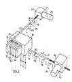
- the uniformity tester shown in FIG. 1 for determining the fluctuations in mass of textile test material, such as yarns, rovings or tapes made of staple fibers, as shown consists of a measuring unit 1, an evaluation unit 2, an output unit 3 and a frame 4 for the presentation units with the Test material P is, for example, yarn or roving bobbins.
- Uniformity testers of this type are known and are distributed worldwide, for example, by the applicant of the present patent application under the name USTER TESTER (USTER registered trademark of Zellweger Uster AG).
- the measuring unit 1 for the test material P consists of several modules, which are arranged in the direction of the test material P, that is, from top to bottom in the figure, as follows: First, a module 5 with a thread guide device 6, for example a thread brake, then one Module 7 with a measuring element 8, then a module 9 with a front thrust device 10 and then a module 11 with a suction nozzle 12.
- the bottom module 11 is placed on a base 13 and all modules 5, 7, 9 and 11 and the base 13 are arranged in a frame 14 with a bow-like upper part 15 and from kept within this framework.
- the suction nozzle 12 is known from the already mentioned USTER TESTER and is not described in more detail here.
- the evaluation unit 2 contains, among other things, an analog / digital converter and a computer and, as shown, is combined with a screen.
- the electrical signals continuously generated by the measuring element 8 are processed by the computer of the evaluation unit 2 and stored in a suitable form in a memory integrated in the evaluation unit 2 and can be displayed on the screen before they are printed out on the printer forming the output unit 3. This has the advantage that you can initially display all the data on the screen and only select selected data for printing on the printer 3.
- the signal processing in the evaluation unit 2 consists of three main components, namely the spectrograph for the so-called spectrogram (wavelength spectrum of the mass fluctuations), and the imperfection indicator, which exceeds the limit value measurements of the mass counts, and from the actual evaluation part for the determination of the so-called coefficient of variation and the length variation curve. All of these parameters are known from the already mentioned USTER TESTER.
- a measuring unit 1 with a different structure which has the following deviations from the measuring unit 1 shown in the figure: - Another measuring element 8 is required, but this is also a capacitive measuring element.
- the feed device 10 must be arranged in the direction of the test material P in front of the measuring element 8.
- a special suction nozzle 12 is required, which gives the filament yarn the twist required for the test. With regard to this suction nozzle, reference is hereby made to US Pat. No. 3,951,321.
- the test material P When passing through the measuring unit 1, the test material P is stretched between the thread guide device 6 and the suction nozzle 12 during the course of its test, the two rollers forming the feed device 10 being arranged in such a way that the test material P is not deflected from its straight path.
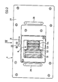
- FIG. 2 shows a perspective view of the most important parts of the measuring element 8 of the measuring unit 1 of the uniformity tester from FIG. 1.
- the measuring element is a so-called capacitive measuring element and consists of a measuring comb with plate-like projections, which measuring gaps S1, S2, Define S3, S4 with different gap widths. Depending on the yarn number of the test material, it passes through a specific measuring gap S1, S2, S3 or S4 during the test.
- the measurement comb 8 is designed to be displaceable transversely to the direction of travel of the test specimen, the axis of each measurement gap S1 to S4 being defined to one Target position is adjustable. It is important that this target position is always the same, i.e. that the test object either does not experience any deflection (target position is defined by the normal position of the test object under tension), or at least always an equally large deflection.
- This displaceability and adjustability of the measuring comb 8 is achieved in that it is mounted on a holding block 16, on which, in addition, a thread oriented in the direction of adjustment of the measuring comb 8 spindle 17 is attached.
- the part of this threaded spindle which is provided with the thread is mounted in a drive part 18 which is fixed in the module 7 (FIG. 1) and which has a motor 19 and a threaded lock (not shown) which can be driven thereby.
- the motor 19 is actuated in one direction or the other, the threaded lock is set in rotation in the corresponding direction and the threaded spindle 17 together with the holding block 16 and measuring comb 8 is moved in the direction of the double arrow A to the left or to the right.
- Corresponding switches T1 to T4 are assigned to the various measuring gaps S1 to S4 along the threaded spindle 17, which switches can be actuated by an organ 20 projecting laterally from the threaded spindle 17.
- the operator enters the required measuring gap S1, S2, S3 or S4 into the evaluation unit 2 (FIG. 1) and thereby starts the motor 19 which adjusts the threaded spindle 17 in the direction of arrow A for so long. until the organ 20 contacts the switch T1, T2, T3 or T4 assigned to the input measuring gap. Since the fineness (yarn number) of the test material is also entered into the evaluation unit 2 for each test and there is a clear relationship between it and the suitable measuring gap, the measuring gap can also be selected automatically on the basis of the entered thread number.
- the test material Before each test, the test material is inserted into the corresponding measuring gap S1, S2, S3 or S4 by an insertion mechanism (not shown).
- the measuring unit 1 (FIG. 1) must then be adjusted to zero The zero balance must be checked.
- a bow-like yarn lifter 21 which is arranged above the measuring comb 8 in the direction of the depth of the measuring gap and is arranged on a threaded spindle 22 which is adjustable in the mentioned direction.
- This threaded spindle 22, like the threaded spindle 17 fastened to the holding block 16, is mounted in a fixed drive part 23 with a motor 24 and a threaded lock (not shown).
- the threaded spindle 22 When the motor 24 is actuated, the threaded spindle 22 is moved forwards or backwards in the direction of the double arrow B, and as a result the test material lying against the thread lifter 21 is either moved out of its measuring gap or can slide back into it.
- the threaded spindle 22 carries a laterally projecting member 25, in the path of which two switches T5 and T6 are arranged, when actuated by the member 25, the motor 24 is stopped. The start of the motor 24 and thus the moving of the test material out of the measuring gap for the purpose of zeroing takes place between two tests or at the end of a series of measurements.
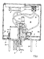
- the module 7 consists of an approximately prismatic housing 26 which is pushed into the frame 14 (FIG. 1).
- the measuring comb 8 with the measuring slits S1 to S4 of different widths, as well as the thread lifter 21, protrudes from the front plate 27 of the housing 26.
- the holding block 23 is screwed onto the inside of the front plate 27 and carries the threaded spindle 22 with the thread lifter 21 on the one hand and the motor 24 on the other hand.
- the holding block 23 is positioned such that the yarn lifter 21 projects into the movement path of the test material P (FIG. 1) stretched between the thread guide device 6 and the suction nozzle 12.
- the holding block 18 for the threaded spindle 17 lies below the holding block 23 and is screwed to the base plate 29 and to the front plate 27 of the module 7.
- the threaded spindle 17 is mounted in the holding block 18 and, as shown, extends over the entire width of the module 7.
- the threaded lock on the threaded spindle 17 is connected to the holding block 16 arranged above the holding block 18 for the threaded spindle 17 with the measuring comb 8, so that when rotating of the threaded lock, the holding block 16 and thus the measuring comb 8 is moved in the direction of the threaded spindle 17.
- the various electrical lines 30 to the measuring comb 8, to the motors 19 and 24 and to the switches T1 to T6 are led to the rear wall of the module 7.
- a fan 31 for cooling and ventilating the inner part of the module 7 is also mounted on this rear wall.
Landscapes
- Engineering & Computer Science (AREA)
- Textile Engineering (AREA)
- Chemical & Material Sciences (AREA)
- Health & Medical Sciences (AREA)
- Life Sciences & Earth Sciences (AREA)
- Analytical Chemistry (AREA)
- Immunology (AREA)
- Physics & Mathematics (AREA)
- Food Science & Technology (AREA)
- Biochemistry (AREA)
- General Health & Medical Sciences (AREA)
- General Physics & Mathematics (AREA)
- Medicinal Chemistry (AREA)
- Pathology (AREA)
- Materials Engineering (AREA)
- Treatment Of Fiber Materials (AREA)
- Measurement Of Length, Angles, Or The Like Using Electric Or Magnetic Means (AREA)
- Investigating Or Analyzing Materials By The Use Of Electric Means (AREA)
- Spinning Or Twisting Of Yarns (AREA)
Applications Claiming Priority (2)
| Application Number | Priority Date | Filing Date | Title |
|---|---|---|---|
| CH4433/86 | 1986-11-06 | ||
| CH4433/86A CH671981A5 (fr) | 1986-11-06 | 1986-11-06 |
Publications (3)
| Publication Number | Publication Date |
|---|---|
| EP0266611A2 true EP0266611A2 (fr) | 1988-05-11 |
| EP0266611A3 EP0266611A3 (en) | 1989-11-08 |
| EP0266611B1 EP0266611B1 (fr) | 1993-06-23 |
Family
ID=4276046
Family Applications (1)
| Application Number | Title | Priority Date | Filing Date |
|---|---|---|---|
| EP87115241A Expired - Lifetime EP0266611B1 (fr) | 1986-11-06 | 1987-10-19 | Appareil pour la détermination automatique de caractéristiques d'un produit textile |
Country Status (8)
| Country | Link |
|---|---|
| EP (1) | EP0266611B1 (fr) |
| JP (1) | JP2589991B2 (fr) |
| KR (1) | KR940011783B1 (fr) |
| CN (1) | CN1011343B (fr) |
| CH (1) | CH671981A5 (fr) |
| DE (1) | DE3786322D1 (fr) |
| ES (1) | ES2040725T3 (fr) |
| IN (1) | IN170324B (fr) |
Cited By (4)
| Publication number | Priority date | Publication date | Assignee | Title |
|---|---|---|---|---|
| DE19908236A1 (de) * | 1999-02-25 | 2000-09-14 | Stein Herbert Textechno | Vorrichtung zur automatischen Prüfung der Gleichmäßigkeit von textilem Prüfgut |
| EP1371979A1 (fr) * | 2002-06-12 | 2003-12-17 | TEWS ELEKTRONIK Dipl.-Ing. Manfred Tews | Dispositif à micro-ondes pour tester la qualité des matériaux en forme de cordon |
| EP1371978A1 (fr) * | 2002-06-12 | 2003-12-17 | TEWS ELEKTRONIK Dipl.-Ing. Manfred Tews | Appareil à micro-ondes pour le contrôle de la qualité des matériaux filamentaires |
| WO2013131198A1 (fr) * | 2012-03-05 | 2013-09-12 | Uster Technologies Ag | Tête de mesure pour essai de fil |
Families Citing this family (2)
| Publication number | Priority date | Publication date | Assignee | Title |
|---|---|---|---|---|
| CN1063046C (zh) * | 1997-09-10 | 2001-03-14 | 沈春楼 | 一种以调节免疫功能来治疗类风湿的抗风湿胶囊 |
| EP2684035B1 (fr) * | 2011-03-11 | 2018-09-12 | Uster Technologies AG | Procédé et dispositif d'investigation capacitive d'un produit à contrôler en mouvement |
Family Cites Families (5)
| Publication number | Priority date | Publication date | Assignee | Title |
|---|---|---|---|---|
| CH519716A (de) * | 1970-08-04 | 1972-02-29 | Zellweger Uster Ag | Textilprüfgerät |
| CH563021A5 (fr) * | 1973-09-26 | 1975-06-13 | Zellweger Uster Ag | |
| DE2707000A1 (de) * | 1976-02-23 | 1977-08-25 | Micro Sensors Inc | Einrichtung zur fortlaufenden kapazitiven messung von charakteristischen groessen eines fadens |
| JPS59145909A (ja) * | 1983-02-09 | 1984-08-21 | Sharp Corp | 寸法測定装置 |
| FR2549096B1 (fr) * | 1983-06-21 | 1985-11-08 | Superba Sa | Procede de controle automatique de fils textiles et appareil pour la mise en oeuvre de ce procede |
-
1986
- 1986-11-06 CH CH4433/86A patent/CH671981A5/de not_active IP Right Cessation
-
1987
- 1987-10-05 IN IN710/MAS/87A patent/IN170324B/en unknown
- 1987-10-19 EP EP87115241A patent/EP0266611B1/fr not_active Expired - Lifetime
- 1987-10-19 ES ES198787115241T patent/ES2040725T3/es not_active Expired - Lifetime
- 1987-10-19 DE DE8787115241T patent/DE3786322D1/de not_active Expired - Fee Related
- 1987-10-27 JP JP62269542A patent/JP2589991B2/ja not_active Expired - Lifetime
- 1987-11-04 KR KR1019870012374A patent/KR940011783B1/ko not_active Expired - Fee Related
- 1987-11-05 CN CN87107691A patent/CN1011343B/zh not_active Expired
Cited By (6)
| Publication number | Priority date | Publication date | Assignee | Title |
|---|---|---|---|---|
| DE19908236A1 (de) * | 1999-02-25 | 2000-09-14 | Stein Herbert Textechno | Vorrichtung zur automatischen Prüfung der Gleichmäßigkeit von textilem Prüfgut |
| EP1371979A1 (fr) * | 2002-06-12 | 2003-12-17 | TEWS ELEKTRONIK Dipl.-Ing. Manfred Tews | Dispositif à micro-ondes pour tester la qualité des matériaux en forme de cordon |
| EP1371978A1 (fr) * | 2002-06-12 | 2003-12-17 | TEWS ELEKTRONIK Dipl.-Ing. Manfred Tews | Appareil à micro-ondes pour le contrôle de la qualité des matériaux filamentaires |
| US6897659B2 (en) | 2002-06-12 | 2005-05-24 | Tews Elektronik | Device for testing the quality of rope-like materials |
| WO2013131198A1 (fr) * | 2012-03-05 | 2013-09-12 | Uster Technologies Ag | Tête de mesure pour essai de fil |
| CH706194A1 (de) * | 2012-03-05 | 2013-09-13 | Uster Technologies Ag | Messkopf zur Prüfung von Garn. |
Also Published As
| Publication number | Publication date |
|---|---|
| KR880006412A (ko) | 1988-07-22 |
| JPS63124961A (ja) | 1988-05-28 |
| CH671981A5 (fr) | 1989-10-13 |
| JP2589991B2 (ja) | 1997-03-12 |
| EP0266611A3 (en) | 1989-11-08 |
| KR940011783B1 (ko) | 1994-12-26 |
| ES2040725T3 (es) | 1993-11-01 |
| CN87107691A (zh) | 1988-05-18 |
| EP0266611B1 (fr) | 1993-06-23 |
| CN1011343B (zh) | 1991-01-23 |
| DE3786322D1 (de) | 1993-07-29 |
| IN170324B (fr) | 1992-03-14 |
Similar Documents
| Publication | Publication Date | Title |
|---|---|---|
| DE3920888C2 (de) | Verfahren zur Prüfung der Enden von gestapelten Zigaretten | |
| EP0626472A1 (fr) | Dispositif pour mesurer l'épaisseur d'une matière fibreuse avec un guide-mèche pour guider la mèche à l'entrée du système d'étirage | |
| WO2003085179A2 (fr) | Machine de preparation de filature | |
| DE3732513C2 (de) | Verfahren und Vorrichtung zum Messen und Prüfen von Stapelfasergarn | |
| CH671105A5 (fr) | ||
| DE69221541T2 (de) | Verfahren und Vorrichtung zum automatischer Analysieren von Teilchen in einer Flüssigkeit | |
| EP0266611B1 (fr) | Appareil pour la détermination automatique de caractéristiques d'un produit textile | |
| DE2041042B2 (de) | Garnwechselvorrichtung, welche einem Prüfgerät automatisch eine An zahl von Garnen zur aufeinanderfol genden Prüfung zufuhrt | |
| EP0266614B1 (fr) | Appareil pour la détermination automatique de caractéristiques d'un produit textile | |
| EP0348443B1 (fr) | Dispositif pour determiner automatiquement la finesse d'un echantillon de textile et utilisation du dispositif | |
| EP0249741B1 (fr) | Procédé de présentation de résultats de mesure sous forme graphique dans des appareils de contrôle pour des échantillons de textile et dispositif pour l'exécution du procédé | |
| US4845983A (en) | Testing apparatus for textile strands | |
| EP0266615B1 (fr) | Appareil pour la détermination automatique de caractéristiques d'un produit textile | |
| EP1035413B1 (fr) | Appareil pour tester automatiquement la régularité d'échantillons textiles | |
| DE3007844A1 (de) | Schreibinstrument | |
| EP0266612B1 (fr) | Appareil pour la détermination automatique de caractéristiques d'un produit textile | |
| EP0356569B1 (fr) | Méthode d'analyse d'échantillons liquides dans des cuvettes et appareil d'analyse pour la mise en oeuvre de ladite méthode | |
| DE857696C (de) | Verfahren und Vorrichtung zur Ermittlung der Reisskraft von fortlaufend bewegten Faeden, Zwirnen, Draehten u. dgl. | |
| DE2708417C2 (de) | Vorrichtung zum Messen einer Querdimension eines längsbewegten kontinuierlichen Gutes | |
| DE3044536A1 (de) | Kopiergeraet | |
| DE2611153B2 (de) | Geraet zur automatischen bestimmung der blutsenkung | |
| DE2426642A1 (de) | Anordnung zur bestimmung sprunghafter dickenaenderungen von blattfoermigem material zur fehl- und doppelblattueberwachung | |
| DE2519231C2 (de) | Vorrichtung zur Überwachung von Kettfäden bei Schärmaschinen auf Flusen und Kapillarbrüche | |
| EP0942282A1 (fr) | Appareil pour mesurer des caractéristiques d'un produit textile | |
| DE29823928U1 (de) | Vorrichtung zum Messen der Dicke und/oder der Ungleichmäßigkeit von Faserbändern |
Legal Events
| Date | Code | Title | Description |
|---|---|---|---|
| PUAI | Public reference made under article 153(3) epc to a published international application that has entered the european phase |
Free format text: ORIGINAL CODE: 0009012 |
|
| AK | Designated contracting states |
Kind code of ref document: A2 Designated state(s): BE DE ES FR GB IT |
|
| PUAL | Search report despatched |
Free format text: ORIGINAL CODE: 0009013 |
|
| AK | Designated contracting states |
Kind code of ref document: A3 Designated state(s): BE DE ES FR GB IT |
|
| 17P | Request for examination filed |
Effective date: 19900319 |
|
| 17Q | First examination report despatched |
Effective date: 19920206 |
|
| ITF | It: translation for a ep patent filed | ||
| GRAA | (expected) grant |
Free format text: ORIGINAL CODE: 0009210 |
|
| AK | Designated contracting states |
Kind code of ref document: B1 Designated state(s): BE DE ES FR GB IT |
|
| PG25 | Lapsed in a contracting state [announced via postgrant information from national office to epo] |
Ref country code: GB Effective date: 19930623 |
|
| REF | Corresponds to: |
Ref document number: 3786322 Country of ref document: DE Date of ref document: 19930729 |
|
| PGFP | Annual fee paid to national office [announced via postgrant information from national office to epo] |
Ref country code: GB Payment date: 19931011 Year of fee payment: 7 |
|
| ET | Fr: translation filed | ||
| REG | Reference to a national code |
Ref country code: ES Ref legal event code: FG2A Ref document number: 2040725 Country of ref document: ES Kind code of ref document: T3 |
|
| GBV | Gb: ep patent (uk) treated as always having been void in accordance with gb section 77(7)/1977 [no translation filed] |
Effective date: 19930623 |
|
| PLBE | No opposition filed within time limit |
Free format text: ORIGINAL CODE: 0009261 |
|
| STAA | Information on the status of an ep patent application or granted ep patent |
Free format text: STATUS: NO OPPOSITION FILED WITHIN TIME LIMIT |
|
| 26N | No opposition filed | ||
| PGFP | Annual fee paid to national office [announced via postgrant information from national office to epo] |
Ref country code: FR Payment date: 19951010 Year of fee payment: 9 |
|
| PGFP | Annual fee paid to national office [announced via postgrant information from national office to epo] |
Ref country code: DE Payment date: 19951026 Year of fee payment: 9 |
|
| PGFP | Annual fee paid to national office [announced via postgrant information from national office to epo] |
Ref country code: ES Payment date: 19951030 Year of fee payment: 9 |
|
| PGFP | Annual fee paid to national office [announced via postgrant information from national office to epo] |
Ref country code: BE Payment date: 19951201 Year of fee payment: 9 |
|
| PG25 | Lapsed in a contracting state [announced via postgrant information from national office to epo] |
Ref country code: ES Free format text: LAPSE BECAUSE OF THE APPLICANT RENOUNCES Effective date: 19961021 |
|
| PG25 | Lapsed in a contracting state [announced via postgrant information from national office to epo] |
Ref country code: BE Effective date: 19961031 |
|
| BERE | Be: lapsed |
Owner name: ZELLWEGER USTER A.G. Effective date: 19961031 |
|
| PG25 | Lapsed in a contracting state [announced via postgrant information from national office to epo] |
Ref country code: FR Effective date: 19970630 |
|
| PG25 | Lapsed in a contracting state [announced via postgrant information from national office to epo] |
Ref country code: DE Effective date: 19970701 |
|
| REG | Reference to a national code |
Ref country code: FR Ref legal event code: ST |
|
| REG | Reference to a national code |
Ref country code: ES Ref legal event code: FD2A Effective date: 19991007 |
|
| PG25 | Lapsed in a contracting state [announced via postgrant information from national office to epo] |
Ref country code: IT Free format text: LAPSE BECAUSE OF NON-PAYMENT OF DUE FEES Effective date: 20051019 |