EP0266760B1 - Maskenwechselsystem hoher Geschwindigkeit - Google Patents
Maskenwechselsystem hoher Geschwindigkeit Download PDFInfo
- Publication number
- EP0266760B1 EP0266760B1 EP87116258A EP87116258A EP0266760B1 EP 0266760 B1 EP0266760 B1 EP 0266760B1 EP 87116258 A EP87116258 A EP 87116258A EP 87116258 A EP87116258 A EP 87116258A EP 0266760 B1 EP0266760 B1 EP 0266760B1
- Authority
- EP
- European Patent Office
- Prior art keywords
- reticle
- reticles
- library
- transport stage
- wafer
- Prior art date
- Legal status (The legal status is an assumption and is not a legal conclusion. Google has not performed a legal analysis and makes no representation as to the accuracy of the status listed.)
- Expired - Lifetime
Links
Images


Classifications
-
- H—ELECTRICITY
- H10—SEMICONDUCTOR DEVICES; ELECTRIC SOLID-STATE DEVICES NOT OTHERWISE PROVIDED FOR
- H10P—GENERIC PROCESSES OR APPARATUS FOR THE MANUFACTURE OR TREATMENT OF DEVICES COVERED BY CLASS H10
- H10P72/00—Handling or holding of wafers, substrates or devices during manufacture or treatment thereof
- H10P72/30—Handling or holding of wafers, substrates or devices during manufacture or treatment thereof for conveying, e.g. between different workstations
- H10P72/34—Handling or holding of wafers, substrates or devices during manufacture or treatment thereof for conveying, e.g. between different workstations the wafers being stored in a carrier, involving loading and unloading
- H10P72/3411—Handling or holding of wafers, substrates or devices during manufacture or treatment thereof for conveying, e.g. between different workstations the wafers being stored in a carrier, involving loading and unloading involving loading and unloading of wafers
-
- G—PHYSICS
- G03—PHOTOGRAPHY; CINEMATOGRAPHY; ANALOGOUS TECHNIQUES USING WAVES OTHER THAN OPTICAL WAVES; ELECTROGRAPHY; HOLOGRAPHY
- G03F—PHOTOMECHANICAL PRODUCTION OF TEXTURED OR PATTERNED SURFACES, e.g. FOR PRINTING, FOR PROCESSING OF SEMICONDUCTOR DEVICES; MATERIALS THEREFOR; ORIGINALS THEREFOR; APPARATUS SPECIALLY ADAPTED THEREFOR
- G03F7/00—Photomechanical, e.g. photolithographic, production of textured or patterned surfaces, e.g. printing surfaces; Materials therefor, e.g. comprising photoresists; Apparatus specially adapted therefor
- G03F7/70—Microphotolithographic exposure; Apparatus therefor
- G03F7/70691—Handling of masks or workpieces
- G03F7/70733—Handling masks and workpieces, e.g. exchange of workpiece or mask, transport of workpiece or mask
- G03F7/70741—Handling masks outside exposure position, e.g. reticle libraries
-
- H—ELECTRICITY
- H10—SEMICONDUCTOR DEVICES; ELECTRIC SOLID-STATE DEVICES NOT OTHERWISE PROVIDED FOR
- H10P—GENERIC PROCESSES OR APPARATUS FOR THE MANUFACTURE OR TREATMENT OF DEVICES COVERED BY CLASS H10
- H10P72/00—Handling or holding of wafers, substrates or devices during manufacture or treatment thereof
- H10P72/30—Handling or holding of wafers, substrates or devices during manufacture or treatment thereof for conveying, e.g. between different workstations
- H10P72/33—Handling or holding of wafers, substrates or devices during manufacture or treatment thereof for conveying, e.g. between different workstations into and out of processing chamber
- H10P72/3306—Horizontal transfer of a single workpiece
-
- H—ELECTRICITY
- H10—SEMICONDUCTOR DEVICES; ELECTRIC SOLID-STATE DEVICES NOT OTHERWISE PROVIDED FOR
- H10P—GENERIC PROCESSES OR APPARATUS FOR THE MANUFACTURE OR TREATMENT OF DEVICES COVERED BY CLASS H10
- H10P72/00—Handling or holding of wafers, substrates or devices during manufacture or treatment thereof
- H10P72/30—Handling or holding of wafers, substrates or devices during manufacture or treatment thereof for conveying, e.g. between different workstations
- H10P72/33—Handling or holding of wafers, substrates or devices during manufacture or treatment thereof for conveying, e.g. between different workstations into and out of processing chamber
- H10P72/3308—Vertical transfer of a single workpiece
Definitions
- This invention relates to the production of semiconductor wafers. More particularly, it relates to method and apparatus for rapidly changing the reticles during wafer production according to the generic clause of claims 1 and 2, respectively.
- Reticles are rapidly transferred between a reticle library and a reticle transport stage by a delivery arm.
- the reticles comprise a circuit reticle, C, which takes relatively long to expose and A and B reticles having relatively short exposure times.
- a holding position is established closely adjacent the transport stage. After the circuit reticle is exposed, it is removed to this holding location.
- a "park" position for the delivery arm is established between the reticle library and the transport stage and relatively closer to the transport stage. While the circuit reticle is in its holding position, reticles A and B traverse a path from the transport stage to the library, from the library to the park position, and from the park position to the transport stage.
- the exposure cycle for successive wafers is in the order BCA-ACB-BCA-ACB.
- reticles A, B, and C Semiconductor chips are formed by coating a semiconductor wafer disc with a photoresist and exposing it to a pattern carried by a glass "reticle". The process is repeated as many times as required. During the normal production of semiconductor wafers, only three reticles are required to expose the wafer. These reticles are referred to herein as reticles A, B, and C. Reticle A would normally consist of test patterns, reticle B might be clear in order to wipe out unexposed photoresist, and reticle C would contain the circuit to be applied to the wafer.
- the apparatus to which this invention relates utilizes an illuminated slit for exposing each wafer. Accordingly, a substantially longer period of time is required to expose reticle C than either of reticles A or B.
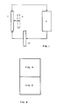
- FIG. 1 illustrates schematically a transport stage T at a loading location, a holding location H located closely adjacent thereto, a reticle library L for storing the reticles between exposures, and a park position P for temporarily supporting a reticle closely adjacent the transport stage prior to its being loaded thereon.
- the arrows indicate the travel of reticles in the load-unload cycle.
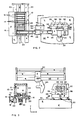
- FIGS. 2 and 3 illustrate apparatus for carrying out the invention. It comprises a reticle library 10 carrying reticles 12 supported therein on library pins 14.
- the reticle library 10 sits on an air bearing carriage 16 which is supported by air bearings 18 on bearing surfaces 20 and driven by a linear motor 22.
- the library 10 moves along the Z axis, the X, Y, and Z axes being indicated by arrows in FIGS. 2 and 3.
- Lifters 24 are positioned beneath the library and function to lift a selected one of the reticles 12 up and off of its library pins 14.
- a reticle transport stage 26 in the form of a carriage 28 supported by three air bearings 30 on a bearing surface 32.
- a vacuum chuck 34 Extending vertically upward from the carriage 28 is a vacuum chuck 34 having reticle support pins 36 for supporting a reticle against the vacuum chuck 34.
- a pair of lifters 38 Positioned below the edge of a reticle so supported are a pair of lifters 38.
- a wafer load/unload holding arm 40 Positioned closely adjacent and parallel to the vacuum chuck 34 is a wafer load/unload holding arm 40.
- the holding arm 40 carries pliant rubber vacuum cups 56 of known type for grasping a wafer.
- the arm 40 is mounted upon a flexure assembly 42 which permits limited movement along the Z axis. This movement is under the control of a conventional air pot which is not shown. Somewhat further motion is provided by mounting the arm 40 and the flexure assembly 42 on an air bearing 44.
- Extending between the library 10 and the transport stage 26 is an air bar 46 supporting an air bearing 48 movable therealong by a linear motor 50.
- a flexure assembly 52 is carried by the air bearing 48 and from it depends a wafer delivery arm 54 which is also provided with pliant vacuum cups 56. Cups of this type are described in U. S. Patent 4,530,635 of Engelbrecht and Laganza.
- the function of the flexure assembly 52 is to permit limited movement of the load/unload arm 54 in the Z direction for the purpose of acquiring and depositing reticles 12.
- the reticles 12 which are likely to be employed in wafer production, are positioned on the pins 14 in the reticle library 10.
- the library is movable along the Z axis to position a reticle such that the load arm 54 can enter the library without hitting the reticle or the library 10.
- the airbearing 48 is then moved along the X axis to position the delivery arm 54 adjacent the selected reticle in the library.
- the library then makes another move along the Z axis to put the arm 54 in the "slot" which holds the library.
- the lifters 24 raise the selected reticle up off the pins 14 and the delivery arm 54 is translated toward it along the Z axis by means of the flexure assembly 52.
- the vacuum cups 56 carried by the arm 54 are forced up against the selected reticle, vacuum switched on, and arm 54 thereby acquires the reticle.
- the lifters 24 thereupon are lowered and the arm 54 retracts along the Z axis.
- the reticle is now no longer touching the library structure and is free to be moved out of the library.
- Delivery arm 54 is then moved along the X axis to the transport stage 26 which is in the load/unload position to receive the reticle.
- the air driven flexure assembly 52 translates the arm 54 along the Z axis until the reticle contacts the vacuum chuck 34.
- the vacuum chuck 34 includes both vacuum and pressurized air ports which hold the reticle closely adjacent the chuck 34 while permitting it to move substantially without friction along the face of the chuck.
- the lifters 38 are raised into contact with the reticle, the vacuum to the delivery arm 54 is switched off, and the arm is retracted.
- the lifters 38 lower the reticle onto the pins 36 and the vacuum chuck 34 is changed to vacuum alone, thereby causing the reticle to firmly adhere to the chuck.
- the next step is to expose a wafer at an exposure station with the reticle.
- the transfer stage 26 moves away from the load/unload position to the exposure station, which is not illustrated herein.
- the transfer stage 26 returns to the load/unload position.
- the selected reticle may be returned to the reticle library 10 by reversing the foregoing procedure. Alternatively, it may be loaded onto the holding arm 40. If this is to be done, the delivery arm 54 must be moved along the X axis toward the library to a position such that it will not interfere with holding arm 40. Holding arm 40 is then translated along the Z axis on the air bearing 44 until it is relatively close to the reticle 12.
- reticles A and B both of which have short exposure times
- circuit reticle C which has a substantially longer exposure time. It is essential that reticles be interchanged as quickly as possible in order to maximize wafer production. The manner in which this is accomplished will be described with reference to the sequence illustrated beginning at the top of FIG. 4.
- circuit reticle C is on the transport stage 26 which, in return, is at the exposure station where the wafer is used to expose wafer I.
- Reticle A is on the delivery arm 54 which is in the park position.
- the holding arm 40 is empty.
- Reticle B has already been used to expose wafer I and is currently stored in the reticle library. Given these initial conditions, the following steps occur:
- the total time to exchange reticles by completing steps 1-6 was no more than 3 seconds.
- Step 7 The transport stage 26 moves away to expose reticle A.
- Step 8 The exposure of wafer I with reticle A, reticle B, and reticle C has been completed and wafer I is replaced by wafer II.
- Step 9 Transport stage 26 exposes wafer II with reticle A and returns to the load/unload position.
- Step 10 The delivery arm 54 translates along the Z axis and acquires reticle A.
- Step 11 The delivery arm 54 retracts along the Z axis with reticle A.
- Step 12 The delivery arm 54 with reticle A translates along the X axis to the park position.
- Step 13 The holding arm 40 loads reticle C onto transport stage 26.
- Step 14 The holding arm 40 retracts along the Z axis.
- the total time required to exchange reticles by completing steps 9-14 is no greater than 3 seconds.
- Step 15 The transport stage 26 moves away to expose the wafer II with reticle C.
- Step 16 While the transport stage 26 is exposing wafer II with reticle C, the delivery arm 54 has translated along the X axis, exchanged reticle A for reticle B at the library 10, and has now translated back along the X axis from the library to the park position.
- the time required to complete step 16 is no greater than 20 seconds. Since, during this period, the wafer II is being exposed by reticle C, this trip to and from the library does not add to the cycle time.
- Step 17 The transport stage 26 exposes wafer II with the reticle C and returns to the load/unload position. Transport stage 26 prepares to unload reticle C as previously explained.
- Step 18 The holding arm 40 translates along the Z axis and acquires reticle C.
- Step 19 The holding arm 40 retracts along the Z axis to its holding position.
- Step 20 The delivery arm 54 moves along the X axis from its park position to the load/unload position with reticle B.
- Step 21 The delivery arm 54 translates along the Z axis and loads reticle B onto transport stage 26.
- Step 22 The delivery arm 54 retracts along the Z axis until it just clears reticle B.
- the total time required to exchange reticles by completing step 17-22 is no more than 3 seconds.
- Step 23 Transport stage 26 moves away to begin the exposure of wafer II with reticle B.
- Step 24 The exposure of wafer II with reticle B is completed. Wafer II has now been exposed by reticle A, reticle B, and reticle C and the wafer is replaced by wafer III.
- Step 25 The cycle now returns to step 9.
- Transport stage 26 exposes wafer III with reticle B and returns to the load/unload position.
- the cycle continues, exposing as many wafers as are required to the reticles A, B, and C.
- the exposure cycle is in the order BCA-ACB-BCA-ACB, i.e., (a) the reticle having the longest exposure time is preceded and followed by the reticles having the shortest exposure time, and (b) the reticle last employed to expose a wafer is the first reticle employed to expose the succeeding wafer.
Landscapes
- Engineering & Computer Science (AREA)
- Library & Information Science (AREA)
- Physics & Mathematics (AREA)
- General Physics & Mathematics (AREA)
- Exposure And Positioning Against Photoresist Photosensitive Materials (AREA)
- Exposure Of Semiconductors, Excluding Electron Or Ion Beam Exposure (AREA)
Claims (2)
- Verfahren zum sequentiellen Laden von drei Masken (A, B, C) auf einen Transportschlitten (26) an einer Ladeposition zum aufeinanderfolgenden Belichten eines jeden einer Vielzahl von Halbleiter-Wafern mit jeder der Masken, wobei eine der Masken eine Schaltkreismaske (C) mit einer wesentlich längeren Belichtungsdauer als die verbleibenden beiden Masken ist, und wobei die verbleibenden beiden Masken (A, B) auf normale Weise in einer relativ weit von der Ladeposition entfernten Maskenaufbewahrungsvorrichtung (10) aufbewahrt sind,
dadurch gekennzeichnet,
daß die Maske (C) in einer nahe an die Ladeposition angrenzenden Halteposition positioniert wird;
die Maske (A) auf dem Transportschlitten (26) positioniert wird;
eine Parkposition zwischen der Aufbewahrungsvorrichtung (10) und der Ladeposition erstellt wird;
ein Wafer mit der Maske (A) belichtet wird;
die Maske (A) von dem Transportschlitten (26) entfernt wird;
die Maske (C) auf dem Transportschlitten (26) positioniert wird;
der Wafer mit der Maske (C) belichtet wird;
während der Belichtungsdauer mit der Maske (C) die Maske (A) zu der Aufbewahrungsvorrichtung (10) bewegt wird und die Maske (B) von der Aufbewahrungsvorrichtung (10) in die Parkposition bewegt wird;
die Maske (C) aus der Halteposition entfernt wird;
die Maske (B) auf dem Transportschlitten (26) positioniert wird;
der Wafer mit der Maske (B) belichtet wird;
der belichtete Wafer gegen einen unbelichteten Wafer ausgetauscht wird und der Belichtungszyklus in der Reihenfolge BCA-ACB-BCA-ACB fortgesetzt wird. - Vorrichtung zum nacheinanderfolgenden Belichten eines jeden einer Vielzahl von Halbleiter-Wafern mit mindestens drei Masken (A, B, C), wobei eine erste der Masken (C) eine wesentlich längere Belichtungsdauer hat als die zweite (A) und dritte (B) der Masken, und wobei die Masken von einer Maskenaufbewahrungsvorrichtung (10) zu einem Transportschlitten (26) in einer Ladeposition zur nacheinanderfolgenden Belichtung bewegt werden,
gekennzeichnet durch
Vorrichtungen (54) zum Positionieren einer der beiden, die zweite und dritte Maske umfassenden Masken auf dem Transportschlitten (26) bei der Ladeposition und zum Positionieren der anderen der beiden, die zweite und dritte Maske umfassenden Masken in der Aufbewahrungsvorrichtung (10);
Vorrichtungen (54, 26, 40), um alternativ die erste Maske entweder auf dem Transportschlitten (26) an der Ladeposition oder an einer nahe an die Ladeposition angrenzenden Halteposition zu positionieren;
Vorrichtungen (54) zum Befördern einer Maske von dem Transportschlitten (26) an der Ladeposition zu der Aufbewahrungsvorrichtung (10) während der Dauer, in der die erste Maske auf dem Transportschlitten (26) sich befindet;
Vorrichtungen (54) zum Befördern der anderen Maske von der Aufbewahrungsvorrichtung (10) zu einer Parkposition, die zwischen der Aufbewahrungsvorrichtung (10) und der Ladeposition liegt, während der Dauer, in der die erste Maske auf dem Transportschlitten (26) sich befindet; und Vorrichtungen (54) zum Weiterbefördern einer Maske von der Parkposition zu dem Transportschlitten (26) an der Ladeposition, während die erste Maske in der Halteposition sich befindet.
Applications Claiming Priority (2)
| Application Number | Priority Date | Filing Date | Title |
|---|---|---|---|
| US06/927,202 US4760429A (en) | 1986-11-05 | 1986-11-05 | High speed reticle change system |
| US927202 | 1986-11-05 |
Publications (3)
| Publication Number | Publication Date |
|---|---|
| EP0266760A2 EP0266760A2 (de) | 1988-05-11 |
| EP0266760A3 EP0266760A3 (en) | 1988-10-05 |
| EP0266760B1 true EP0266760B1 (de) | 1993-09-01 |
Family
ID=25454380
Family Applications (1)
| Application Number | Title | Priority Date | Filing Date |
|---|---|---|---|
| EP87116258A Expired - Lifetime EP0266760B1 (de) | 1986-11-05 | 1987-11-04 | Maskenwechselsystem hoher Geschwindigkeit |
Country Status (6)
| Country | Link |
|---|---|
| US (1) | US4760429A (de) |
| EP (1) | EP0266760B1 (de) |
| JP (1) | JP2679763B2 (de) |
| KR (1) | KR950012907B1 (de) |
| CA (1) | CA1277443C (de) |
| DE (1) | DE3787245T2 (de) |
Cited By (1)
| Publication number | Priority date | Publication date | Assignee | Title |
|---|---|---|---|---|
| US7230673B2 (en) | 2004-12-07 | 2007-06-12 | Asml Netherlands B.V. | Lithographic apparatus, reticle exchange unit and device manufacturing method |
Families Citing this family (17)
| Publication number | Priority date | Publication date | Assignee | Title |
|---|---|---|---|---|
| US5498118A (en) * | 1992-02-07 | 1996-03-12 | Nikon Corporation | Apparatus for and method of carrying a substrate |
| US6473157B2 (en) * | 1992-02-07 | 2002-10-29 | Nikon Corporation | Method of manufacturing exposure apparatus and method for exposing a pattern on a mask onto a substrate |
| KR100399813B1 (ko) * | 1994-12-14 | 2004-06-09 | 가부시키가이샤 니콘 | 노광장치 |
| US5621565A (en) * | 1995-10-04 | 1997-04-15 | Leica Ag | Protraction device for a measuring microscope |
| TW490594B (en) * | 1999-06-09 | 2002-06-11 | Asm Lithography Bv | Lithographic projection method |
| US6239863B1 (en) | 1999-10-08 | 2001-05-29 | Silicon Valley Group, Inc. | Removable cover for protecting a reticle, system including and method of using the same |
| DE60219844T2 (de) * | 2001-03-01 | 2008-01-17 | Asml Netherlands B.V. | Verfahren zur Übernahme einer lithographischen Maske |
| US6809793B1 (en) | 2002-01-16 | 2004-10-26 | Advanced Micro Devices, Inc. | System and method to monitor reticle heating |
| US6906783B2 (en) * | 2002-02-22 | 2005-06-14 | Asml Holding N.V. | System for using a two part cover for protecting a reticle |
| US6757110B2 (en) * | 2002-05-29 | 2004-06-29 | Asml Holding N.V. | Catadioptric lithography system and method with reticle stage orthogonal to wafer stage |
| TWI245170B (en) * | 2003-07-22 | 2005-12-11 | Asml Netherlands Bv | Lithographic apparatus, device manufacturing method, and device manufactured thereby |
| EP1500980A1 (de) * | 2003-07-22 | 2005-01-26 | ASML Netherlands B.V. | Lithographischer Projektionsapparat, Verfahren zur Herstellung eines Artikels und dabei erzeugter Artikel |
| US6862817B1 (en) | 2003-11-12 | 2005-03-08 | Asml Holding N.V. | Method and apparatus for kinematic registration of a reticle |
| KR20060007211A (ko) * | 2004-07-19 | 2006-01-24 | 삼성전자주식회사 | 노광 시스템 |
| US7665981B2 (en) * | 2005-08-25 | 2010-02-23 | Molecular Imprints, Inc. | System to transfer a template transfer body between a motion stage and a docking plate |
| US20070064384A1 (en) * | 2005-08-25 | 2007-03-22 | Molecular Imprints, Inc. | Method to transfer a template transfer body between a motion stage and a docking plate |
| US20070074635A1 (en) * | 2005-08-25 | 2007-04-05 | Molecular Imprints, Inc. | System to couple a body and a docking plate |
Family Cites Families (8)
| Publication number | Priority date | Publication date | Assignee | Title |
|---|---|---|---|---|
| JPS546866B2 (de) * | 1971-08-25 | 1979-04-02 | ||
| JPS52109875A (en) * | 1976-02-25 | 1977-09-14 | Hitachi Ltd | Position matching system for mask and wafer and its unit |
| JPS55132039A (en) * | 1979-04-02 | 1980-10-14 | Mitsubishi Electric Corp | Forming method for repeated figure |
| NL8101668A (nl) * | 1981-04-03 | 1982-11-01 | Philips Nv | Inrichting voor het detekteren van de positie van een voorwerp. |
| US4444492A (en) * | 1982-05-15 | 1984-04-24 | General Signal Corporation | Apparatus for projecting a series of images onto dies of a semiconductor wafer |
| US4530635A (en) * | 1983-06-15 | 1985-07-23 | The Perkin-Elmer Corporation | Wafer transferring chuck assembly |
| JPS61100932A (ja) * | 1984-10-24 | 1986-05-19 | Hitachi Ltd | 露光装置 |
| DE8528934U1 (de) * | 1985-10-11 | 1985-12-19 | B. Bacher GmbH, 7204 Wurmlingen | Repetier-Kopiermaschine |
-
1986
- 1986-11-05 US US06/927,202 patent/US4760429A/en not_active Expired - Lifetime
-
1987
- 1987-11-03 CA CA000550965A patent/CA1277443C/en not_active Expired - Lifetime
- 1987-11-04 EP EP87116258A patent/EP0266760B1/de not_active Expired - Lifetime
- 1987-11-04 DE DE87116258T patent/DE3787245T2/de not_active Expired - Lifetime
- 1987-11-05 JP JP62278417A patent/JP2679763B2/ja not_active Expired - Lifetime
- 1987-11-05 KR KR1019870012431A patent/KR950012907B1/ko not_active Expired - Lifetime
Cited By (1)
| Publication number | Priority date | Publication date | Assignee | Title |
|---|---|---|---|---|
| US7230673B2 (en) | 2004-12-07 | 2007-06-12 | Asml Netherlands B.V. | Lithographic apparatus, reticle exchange unit and device manufacturing method |
Also Published As
| Publication number | Publication date |
|---|---|
| DE3787245D1 (de) | 1993-10-07 |
| EP0266760A3 (en) | 1988-10-05 |
| JPS63296219A (ja) | 1988-12-02 |
| JP2679763B2 (ja) | 1997-11-19 |
| DE3787245T2 (de) | 1994-02-24 |
| EP0266760A2 (de) | 1988-05-11 |
| CA1277443C (en) | 1990-12-04 |
| KR880006758A (ko) | 1988-07-25 |
| US4760429A (en) | 1988-07-26 |
| KR950012907B1 (ko) | 1995-10-23 |
Similar Documents
| Publication | Publication Date | Title |
|---|---|---|
| EP0266760B1 (de) | Maskenwechselsystem hoher Geschwindigkeit | |
| KR100251340B1 (ko) | 기판처리장치 및 기판처리방법 | |
| KR100242533B1 (ko) | 반도체 처리시스템 및 기판의 교환방법 및 처리방법 | |
| US5100502A (en) | Semiconductor wafer transfer in processing systems | |
| US5711646A (en) | Substrate transfer apparatus | |
| US5803932A (en) | Resist processing apparatus having an interface section including two stacked substrate waiting tables | |
| US4775281A (en) | Apparatus and method for loading and unloading wafers | |
| JP3579228B2 (ja) | 基板処理装置 | |
| CN108028218B (zh) | 衬底搬送机器人及衬底处理系统 | |
| JPS5931211B2 (ja) | 製造装置 | |
| KR101139180B1 (ko) | 기판 반송 방법 및 기판 반송 장치 | |
| US4119211A (en) | Method and apparatus for transferring articles while re-establishing their orientation | |
| JP2000331922A (ja) | 基板処理装置 | |
| US4775877A (en) | Method and apparatus for processing a plate-like workpiece | |
| JP2002520860A (ja) | ウェハーを極小接触でハンドリングするためのウェハーキャリア及び方法 | |
| WO1991018400A1 (en) | Mask tray for and method of loading mask in lithography system | |
| JP2535821B2 (ja) | 基板の▲高▼速変換装置及び方法 | |
| JPH07130637A (ja) | 半導体製造装置 | |
| JPH11340297A (ja) | 基板搬送装置および方法 | |
| JPH02164017A (ja) | 半導体製造装置 | |
| JP2976317B2 (ja) | 板状体の処理装置及び板状体の搬送方法 | |
| JPH0484410A (ja) | レジスト処理装置 | |
| JP2743274B2 (ja) | 基板処理装置および基板搬送装置 | |
| JP2926213B2 (ja) | 基板処理装置 | |
| CN222071048U (zh) | 一种涂胶显影设备 |
Legal Events
| Date | Code | Title | Description |
|---|---|---|---|
| PUAI | Public reference made under article 153(3) epc to a published international application that has entered the european phase |
Free format text: ORIGINAL CODE: 0009012 |
|
| AK | Designated contracting states |
Kind code of ref document: A2 Designated state(s): DE FR GB IT NL |
|
| PUAL | Search report despatched |
Free format text: ORIGINAL CODE: 0009013 |
|
| AK | Designated contracting states |
Kind code of ref document: A3 Designated state(s): DE FR GB IT NL |
|
| 17P | Request for examination filed |
Effective date: 19890405 |
|
| RAP1 | Party data changed (applicant data changed or rights of an application transferred) |
Owner name: SVG LITHOGRAPHY SYSTEMS, INC. |
|
| 17Q | First examination report despatched |
Effective date: 19911113 |
|
| ITF | It: translation for a ep patent filed | ||
| GRAA | (expected) grant |
Free format text: ORIGINAL CODE: 0009210 |
|
| AK | Designated contracting states |
Kind code of ref document: B1 Designated state(s): DE FR GB IT NL |
|
| REF | Corresponds to: |
Ref document number: 3787245 Country of ref document: DE Date of ref document: 19931007 |
|
| ET | Fr: translation filed | ||
| PLBE | No opposition filed within time limit |
Free format text: ORIGINAL CODE: 0009261 |
|
| STAA | Information on the status of an ep patent application or granted ep patent |
Free format text: STATUS: NO OPPOSITION FILED WITHIN TIME LIMIT |
|
| 26N | No opposition filed | ||
| REG | Reference to a national code |
Ref country code: GB Ref legal event code: IF02 |
|
| PGFP | Annual fee paid to national office [announced via postgrant information from national office to epo] |
Ref country code: NL Payment date: 20061110 Year of fee payment: 20 |
|
| PGFP | Annual fee paid to national office [announced via postgrant information from national office to epo] |
Ref country code: DE Payment date: 20061124 Year of fee payment: 20 Ref country code: FR Payment date: 20061124 Year of fee payment: 20 |
|
| PGFP | Annual fee paid to national office [announced via postgrant information from national office to epo] |
Ref country code: GB Payment date: 20061127 Year of fee payment: 20 |
|
| PGFP | Annual fee paid to national office [announced via postgrant information from national office to epo] |
Ref country code: IT Payment date: 20061130 Year of fee payment: 20 |
|
| REG | Reference to a national code |
Ref country code: GB Ref legal event code: PE20 |
|
| NLV7 | Nl: ceased due to reaching the maximum lifetime of a patent |
Effective date: 20071104 |
|
| PG25 | Lapsed in a contracting state [announced via postgrant information from national office to epo] |
Ref country code: NL Free format text: LAPSE BECAUSE OF EXPIRATION OF PROTECTION Effective date: 20071104 |
|
| PG25 | Lapsed in a contracting state [announced via postgrant information from national office to epo] |
Ref country code: GB Free format text: LAPSE BECAUSE OF EXPIRATION OF PROTECTION Effective date: 20071103 |