EP0266762A2 - Appareil électrique de commutation limitant le courant - Google Patents
Appareil électrique de commutation limitant le courant Download PDFInfo
- Publication number
- EP0266762A2 EP0266762A2 EP87116282A EP87116282A EP0266762A2 EP 0266762 A2 EP0266762 A2 EP 0266762A2 EP 87116282 A EP87116282 A EP 87116282A EP 87116282 A EP87116282 A EP 87116282A EP 0266762 A2 EP0266762 A2 EP 0266762A2
- Authority
- EP
- European Patent Office
- Prior art keywords
- contact arm
- locking
- switching device
- switching
- housing
- Prior art date
- Legal status (The legal status is an assumption and is not a legal conclusion. Google has not performed a legal analysis and makes no representation as to the accuracy of the status listed.)
- Granted
Links
Images


Classifications
-
- H—ELECTRICITY
- H01—ELECTRIC ELEMENTS
- H01H—ELECTRIC SWITCHES; RELAYS; SELECTORS; EMERGENCY PROTECTIVE DEVICES
- H01H77/00—Protective overload circuit-breaking switches operated by excess current and requiring separate action for resetting
- H01H77/02—Protective overload circuit-breaking switches operated by excess current and requiring separate action for resetting in which the excess current itself provides the energy for opening the contacts, and having a separate reset mechanism
- H01H77/10—Protective overload circuit-breaking switches operated by excess current and requiring separate action for resetting in which the excess current itself provides the energy for opening the contacts, and having a separate reset mechanism with electrodynamic opening
-
- H—ELECTRICITY
- H01—ELECTRIC ELEMENTS
- H01H—ELECTRIC SWITCHES; RELAYS; SELECTORS; EMERGENCY PROTECTIVE DEVICES
- H01H77/00—Protective overload circuit-breaking switches operated by excess current and requiring separate action for resetting
- H01H77/02—Protective overload circuit-breaking switches operated by excess current and requiring separate action for resetting in which the excess current itself provides the energy for opening the contacts, and having a separate reset mechanism
- H01H77/10—Protective overload circuit-breaking switches operated by excess current and requiring separate action for resetting in which the excess current itself provides the energy for opening the contacts, and having a separate reset mechanism with electrodynamic opening
- H01H77/102—Protective overload circuit-breaking switches operated by excess current and requiring separate action for resetting in which the excess current itself provides the energy for opening the contacts, and having a separate reset mechanism with electrodynamic opening characterised by special mounting of contact arm, allowing blow-off movement
- H01H77/104—Protective overload circuit-breaking switches operated by excess current and requiring separate action for resetting in which the excess current itself provides the energy for opening the contacts, and having a separate reset mechanism with electrodynamic opening characterised by special mounting of contact arm, allowing blow-off movement with a stable blow-off position
Definitions
- the invention relates to an electrical switching device according to the preamble of claim 1.
- the shortest possible switch-off delay times (e.g. 2 ms or less) are required. These times cannot be achieved with the usual lock constructions (on / off mechanism, quick release device by means of a magnetic release) due to the masses to be accelerated and the lever paths to be traveled.
- the short-circuit current itself must therefore contribute to the accelerated opening of the switching elements (dynamic opening).
- the electrodynamic effect on the contact arms is generally relatively small in the nominal current and overload range, but in the event of a short circuit, usable forces result from the quadratic current dependence. Currents are problematic, the amplitude of which causes lifting and a slight opening of the contact pieces, but is too small for further acceleration of the contact arm masses are. This can lead to the contacts being closed again or to undesired bouncing processes.
- DE-OS 1463 320 a construction is known from DE-OS 1463 320 in which a releasable rack coupling is present between the movable contact piece of the contact system and a rotary or pivoting lever causing the release of a switching lock, which has a frictional connection between the movable contact piece and the rotary or swivel lever produces when the movable contact piece strives to perform a closing movement opposite to the opening movement during the opening process, e.g. B. when rebounding from a stop or with an imperfect opening.
- the object of the invention is to improve a switching device of the type mentioned above in such a way that after an electrodynamic opening of the contact system with simple means a reliable locking of the movable switching contact arm is ensured in any position dependent on the opening forces, which can be released again.
- the additional switching function can be integrated with relatively few construction parts, and the arc extinguishing is improved with increased security for the switching system and the subordinate and elements to be protected.
- the lock release mechanism can be made simpler since its mechanical delay time is no longer critical for the switch-off behavior.
- a minimum contact distance can be set at which the earliest it can be kept open after dynamic lifting.
- skilful shaping of the locking lugs a progressive inhibition can be achieved on the opening switch contact arm, which prevents strong opening and / or bouncing back at very high currents.
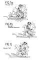
- the switch is in the switch position "on".
- the contact piece 1 on the movable contact arm 2 lies on the fixed contact piece 3, which is arranged on a loop-shaped power supply 4.
- the key switch 5 is in the locked position.
- a certain contact force is predetermined by the lever mechanism and a spring 6.
- a toothing 7 is attached, which interacts with a spring 8 arranged in the housing bottom.
- the lower knee joint lever 9 of the switching lock 5 and the switching shaft 10 are articulated on the contact arm 2 via a lever 11 by means of a bolt 12.
- the movable contact arm 2 is repelled against the force of the spring 6 by the forces which arise from the loop-shaped design of the power supply and rotates about an axis A (bolt 12) on a circular path a (FIG. 1b switch dynamically opened ). If the repulsive force overall is so strong that the spring 8 engages at least in the first toothing 7, a renewed closing or rebounding of the contacts is no longer possible. The arc between the contact pieces must commute as quickly as possible from these on tracks or directly into an extinguishing system.
- the now unlocked switch lock 5 acts a short time later on the contact arm 2 and lifts it in another way b around the pivot point B, the latching being released. The arm is guided on path b to the end position (Fig. 1c switch open).
- a stepless inhibition is achieved in that the contact arm 2 instead of a toothing as in the example according to FIG. 1 has a part 13 rounded off with a radius r, which cooperates with a spring-loaded friction roller 14, 15 in the housing base.
- the contact arm 2 can be moved along the roller 15.
- the roller 15 wedges in the opposite direction (closing of the contacts) the contact arm 2 with the housing bottom.
- the escapement is released again when the mechanical switching lock 5 lifts the contact arm 2 from path a with the pivot point A to path b with the pivot point B in the direction of the switch-off position
- FIG. 2c. 2b shows the dynamic open position in which the contact arm 2 is prevented from returning by the friction roller 15.
- the variant according to FIG. 3 differs from the embodiment according to FIG. 1 in principle in that the cams 17 for latching or latching are part of a housing or bulkhead wall 18 or can be inserted into this as a special component.
- the counterpart for the cams 17 can be a bolt 19 in the contact arm 2.
- FIG. 4 Another solution to the problem is shown in FIG. 4. Thereafter, cams 21 are mounted in opposite housing walls 20. A limitation to certain radii is not necessary.
- the locking takes place by means of an elastic cam 22 on the movable contact arm 2.
- the force in the opening direction causes the cams to "ratchet” until the contact arm 2 stops.
- the movement of the arm back or even in the fully open position of the switching device requires at least one force F to overcome it another cam.
- This force must be applied from the unlocked switch lock to the opening or from the mechanical or electrical actuation unit (spring-loaded mechanism, coil, armature, motor drive, manual operating device).
Landscapes
- Physics & Mathematics (AREA)
- Electromagnetism (AREA)
- Driving Mechanisms And Operating Circuits Of Arc-Extinguishing High-Tension Switches (AREA)
- Rotary Switch, Piano Key Switch, And Lever Switch (AREA)
- Emergency Protection Circuit Devices (AREA)
- Fuses (AREA)
- Switch Cases, Indication, And Locking (AREA)
- Connection Of Motors, Electrical Generators, Mechanical Devices, And The Like (AREA)
Priority Applications (1)
| Application Number | Priority Date | Filing Date | Title |
|---|---|---|---|
| AT87116282T ATE84914T1 (de) | 1986-11-06 | 1987-11-05 | Strombegrenzendes elektrisches schaltgeraet. |
Applications Claiming Priority (2)
| Application Number | Priority Date | Filing Date | Title |
|---|---|---|---|
| DE3637913 | 1986-11-06 | ||
| DE19863637913 DE3637913A1 (de) | 1986-11-06 | 1986-11-06 | Strombegrenzendes elektrisches schaltgeraet |
Publications (3)
| Publication Number | Publication Date |
|---|---|
| EP0266762A2 true EP0266762A2 (fr) | 1988-05-11 |
| EP0266762A3 EP0266762A3 (en) | 1989-02-22 |
| EP0266762B1 EP0266762B1 (fr) | 1993-01-20 |
Family
ID=6313357
Family Applications (1)
| Application Number | Title | Priority Date | Filing Date |
|---|---|---|---|
| EP87116282A Expired - Lifetime EP0266762B1 (fr) | 1986-11-06 | 1987-11-05 | Appareil électrique de commutation limitant le courant |
Country Status (3)
| Country | Link |
|---|---|
| EP (1) | EP0266762B1 (fr) |
| AT (1) | ATE84914T1 (fr) |
| DE (2) | DE3637913A1 (fr) |
Cited By (2)
| Publication number | Priority date | Publication date | Assignee | Title |
|---|---|---|---|---|
| EP0827174A1 (fr) * | 1996-09-03 | 1998-03-04 | Eaton Corporation | Disjoncteur avec verrouillage pour éviter le rebond du bras de contact après l'ouverture électrodynamique |
| WO2007036282A1 (fr) * | 2005-09-29 | 2007-04-05 | Abb Ag | Appareil d'installation electrique |
Family Cites Families (7)
| Publication number | Priority date | Publication date | Assignee | Title |
|---|---|---|---|---|
| GB1052519A (fr) * | 1963-04-11 | 1900-01-01 | ||
| DE1986601U (de) * | 1963-04-11 | 1968-06-06 | Licentia Gmbh | Selbstschalter. |
| DE1463320A1 (de) * | 1963-06-28 | 1969-03-27 | Licentia Gmbh | Selbstschalter |
| US4409573A (en) * | 1981-04-23 | 1983-10-11 | Siemens-Allis, Inc. | Electromagnetically actuated anti-rebound latch |
| US4528531A (en) * | 1983-12-19 | 1985-07-09 | Westinghouse Electric Corp. | Molded case circuit breaker with improved operating mechanism |
| US4594567A (en) * | 1984-09-28 | 1986-06-10 | Siemens-Allis, Inc. | Circuit breaker contact arm assembly having a magnetic carrier |
| US4608545A (en) * | 1985-09-24 | 1986-08-26 | Siemens-Allis, Inc. | Movable contact arm assembly for a current limiting circuit breaker |
-
1986
- 1986-11-06 DE DE19863637913 patent/DE3637913A1/de active Granted
-
1987
- 1987-11-05 AT AT87116282T patent/ATE84914T1/de not_active IP Right Cessation
- 1987-11-05 DE DE8787116282T patent/DE3783719D1/de not_active Expired - Fee Related
- 1987-11-05 EP EP87116282A patent/EP0266762B1/fr not_active Expired - Lifetime
Cited By (3)
| Publication number | Priority date | Publication date | Assignee | Title |
|---|---|---|---|---|
| EP0827174A1 (fr) * | 1996-09-03 | 1998-03-04 | Eaton Corporation | Disjoncteur avec verrouillage pour éviter le rebond du bras de contact après l'ouverture électrodynamique |
| US5793270A (en) * | 1996-09-03 | 1998-08-11 | Eaton Corporation | Circuit breaker with latch preventing rebound of blow open contact arm |
| WO2007036282A1 (fr) * | 2005-09-29 | 2007-04-05 | Abb Ag | Appareil d'installation electrique |
Also Published As
| Publication number | Publication date |
|---|---|
| ATE84914T1 (de) | 1993-02-15 |
| EP0266762B1 (fr) | 1993-01-20 |
| EP0266762A3 (en) | 1989-02-22 |
| DE3637913A1 (de) | 1988-05-19 |
| DE3783719D1 (de) | 1993-03-04 |
| DE3637913C2 (fr) | 1989-10-19 |
Similar Documents
| Publication | Publication Date | Title |
|---|---|---|
| DE69016111T2 (de) | Begrenzungsschalter mit einer elektromagnetischen Vorrichtung zur Verzögerung des Zurückfallens des Kontaktes. | |
| EP0584503B1 (fr) | Serrure pour disjoncteur | |
| EP1078381B1 (fr) | Commande magnetique bistable pour un commutateur | |
| DE102004051184A1 (de) | Kontaktvorrichtung eines Schutzschalters vom Repulsionstyp | |
| DE10150550C1 (de) | Kontaktanordnung für strombegrenzende Schutzschalter | |
| DE19540972A1 (de) | Strombegrenzendes Kontaktsystem mit Doppeltunterbrechung für Niederspannungs-Schutzschalter | |
| DE102011008831A1 (de) | Istallationsschaltgerät | |
| EP1334503B1 (fr) | Systeme de contact pour disjoncteurs limiteurs de courant | |
| EP0916151B1 (fr) | Disjoncteur limiteur de courant | |
| EP0266762B1 (fr) | Appareil électrique de commutation limitant le courant | |
| EP1334499A1 (fr) | Dispositif de contact pour disjoncteurs de protection limiteurs de courant | |
| EP0508041B1 (fr) | Commande de commutation pour appareils électriques à moyenne tension | |
| DE9305858U1 (de) | Handbetätigungsvorrichtung für gekapselte elektrische Schaltgeräte | |
| DE10219022B3 (de) | Kontaktanordnung für strombegrenzende Schutzschalter | |
| EP1334504B1 (fr) | Systeme de contact pour disjoncteurs limiteurs de courant | |
| EP0744080A1 (fr) | Coupe-circuit basse tension a commutateur auxiliaire relatif | |
| DE112005003632B4 (de) | Leistungsschalter | |
| DE69615189T2 (de) | Schalter | |
| DE10218526B4 (de) | Schaltgerät | |
| DE4023740C2 (de) | Schalterantrieb | |
| DE10056821A1 (de) | Kontaktanordnung für strombegrenzende Schutzschalter | |
| DE102009025519B4 (de) | Auslöser für ein elektrisches Schaltgerät | |
| EP1473753A1 (fr) | Appareil de commutation électrique | |
| DE1042708B (de) | Einrichtung an einem mittels einer Tuer zu oeffnenden Gehaeuse fuer die Aufnahme eines elektrischen Geraetes | |
| DE10061783C1 (de) | Verriegelungsvorrichtung |
Legal Events
| Date | Code | Title | Description |
|---|---|---|---|
| PUAI | Public reference made under article 153(3) epc to a published international application that has entered the european phase |
Free format text: ORIGINAL CODE: 0009012 |
|
| AK | Designated contracting states |
Kind code of ref document: A2 Designated state(s): AT BE CH DE FR GB IT LI SE |
|
| PUAL | Search report despatched |
Free format text: ORIGINAL CODE: 0009013 |
|
| AK | Designated contracting states |
Kind code of ref document: A3 Designated state(s): AT BE CH DE FR GB IT LI SE |
|
| 17P | Request for examination filed |
Effective date: 19890307 |
|
| 17Q | First examination report despatched |
Effective date: 19910708 |
|
| GRAA | (expected) grant |
Free format text: ORIGINAL CODE: 0009210 |
|
| AK | Designated contracting states |
Kind code of ref document: B1 Designated state(s): AT BE CH DE FR GB IT LI SE |
|
| REF | Corresponds to: |
Ref document number: 84914 Country of ref document: AT Date of ref document: 19930215 Kind code of ref document: T |
|
| REF | Corresponds to: |
Ref document number: 3783719 Country of ref document: DE Date of ref document: 19930304 |
|
| ET | Fr: translation filed | ||
| ITF | It: translation for a ep patent filed | ||
| GBT | Gb: translation of ep patent filed (gb section 77(6)(a)/1977) |
Effective date: 19930422 |
|
| PG25 | Lapsed in a contracting state [announced via postgrant information from national office to epo] |
Ref country code: GB Effective date: 19931105 Ref country code: AT Effective date: 19931105 |
|
| PG25 | Lapsed in a contracting state [announced via postgrant information from national office to epo] |
Ref country code: SE Effective date: 19931106 |
|
| PLBE | No opposition filed within time limit |
Free format text: ORIGINAL CODE: 0009261 |
|
| STAA | Information on the status of an ep patent application or granted ep patent |
Free format text: STATUS: NO OPPOSITION FILED WITHIN TIME LIMIT |
|
| PG25 | Lapsed in a contracting state [announced via postgrant information from national office to epo] |
Ref country code: LI Effective date: 19931130 Ref country code: CH Effective date: 19931130 Ref country code: BE Effective date: 19931130 |
|
| 26N | No opposition filed | ||
| BERE | Be: lapsed |
Owner name: LICENTIA PATENT-VERWALTUNGS-G.M.B.H. Effective date: 19931130 |
|
| GBPC | Gb: european patent ceased through non-payment of renewal fee |
Effective date: 19931105 |
|
| PG25 | Lapsed in a contracting state [announced via postgrant information from national office to epo] |
Ref country code: FR Effective date: 19940729 |
|
| REG | Reference to a national code |
Ref country code: CH Ref legal event code: PL |
|
| REG | Reference to a national code |
Ref country code: FR Ref legal event code: ST |
|
| PGFP | Annual fee paid to national office [announced via postgrant information from national office to epo] |
Ref country code: DE Payment date: 19941026 Year of fee payment: 8 |
|
| EUG | Se: european patent has lapsed |
Ref document number: 87116282.2 Effective date: 19940610 |
|
| PG25 | Lapsed in a contracting state [announced via postgrant information from national office to epo] |
Ref country code: DE Effective date: 19960801 |
|
| PG25 | Lapsed in a contracting state [announced via postgrant information from national office to epo] |
Ref country code: IT Free format text: LAPSE BECAUSE OF NON-PAYMENT OF DUE FEES;WARNING: LAPSES OF ITALIAN PATENTS WITH EFFECTIVE DATE BEFORE 2007 MAY HAVE OCCURRED AT ANY TIME BEFORE 2007. THE CORRECT EFFECTIVE DATE MAY BE DIFFERENT FROM THE ONE RECORDED. Effective date: 20051105 |